Final Project: Design of an Electric Vehicle
OBJECTIVE: To create a model of an Electric Vehicle with appropriate motor, controller and vehicle subsystem designs
MODELING:
Modeling of an EV in SImulink consists of creating the vehicle body, motor, motor controller, driver and drive cycle systems with the appropriate parameters. Default Solver configuration is used for this model.
Vehicle body Subsystem: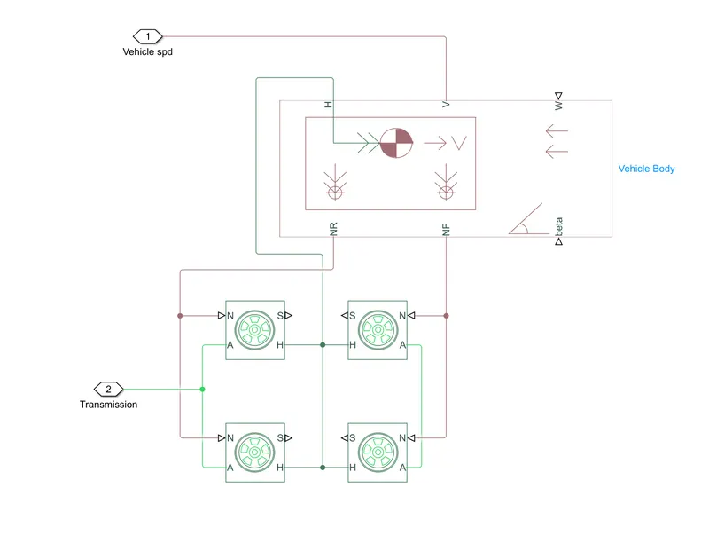
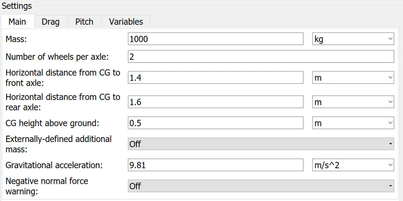
We use a vehicle body block and assign the assumed vehicle parameters.
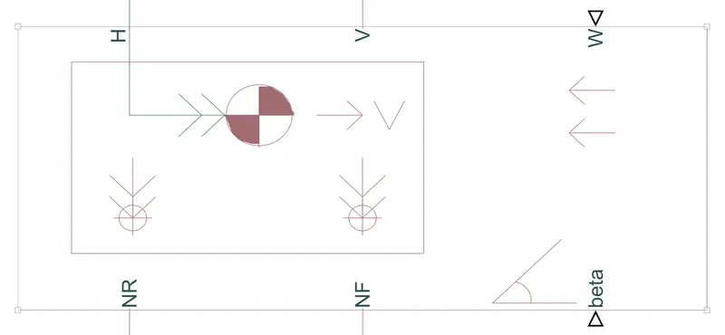
A vehicle body block represents a two-axle vehicle body in longitudinal motion. The block accounts for body mass, aerodynamic drag, road incline, and weight distribution between axles due to acceleration and road profile. The vehicle can have the same or a different number of wheels on each axle. Optionally include pitch and suspension dynamics or additional variable mass and inertia. The vehicle does not move vertically relative to the ground.
Settings:
Magic formula tyres are used to connect to the vehicle body.
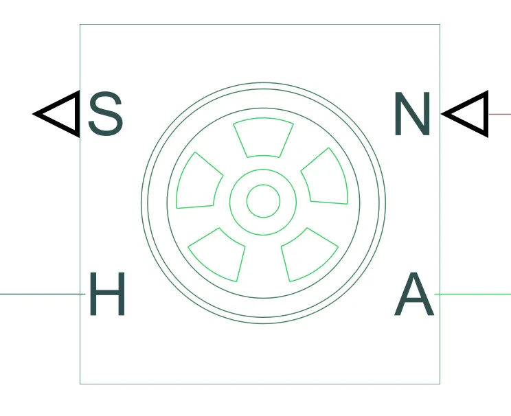
Represents the longitudinal behavior of a highway tire characterized by the tire Magic Formula. The block is built from Tire-Road Interaction (Magic Formula) and Simscape Foundation Library Wheel and Axle blocks. Optionally, the effects of tire inertia, stiffness, and damping can be included.
The vehicle speed and transmission outputs are used for the longitudinal driver feedback and the simple gear respectively.
Motor and Controller modelling:
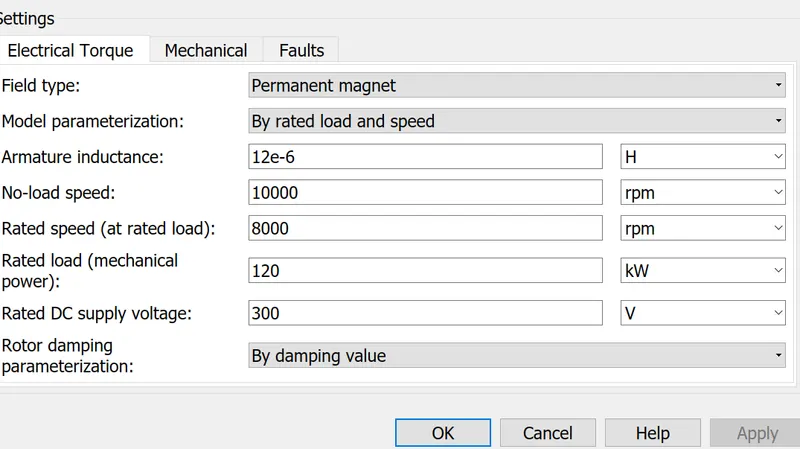
Next we used a DC motor with the assumed parameters and connect the output to the transmission through the simple gear:
DC motor block:
This block represents the electrical and torque characteristics of a DC motor.
The block assumes that no electromagnetic energy is lost, and hence the back-emf and torque constants have the same numerical value when in SI units. Motor parameters can either be specified directly, or derived from no-load speed and stall torque. If no information is available on armature inductance, this parameter can be set to some small non-zero value.
When a positive current flows from the electrical + to - ports, a positive torque acts from the mechanical C to R ports. Motor torque direction can be changed by altering the sign of the back-emf or torque constants.
DC motor parameters:
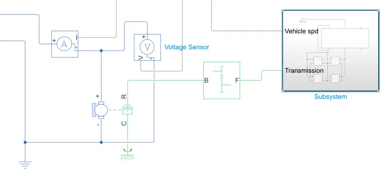
The voltage sensor is used to sense the armature voltage across the motor.
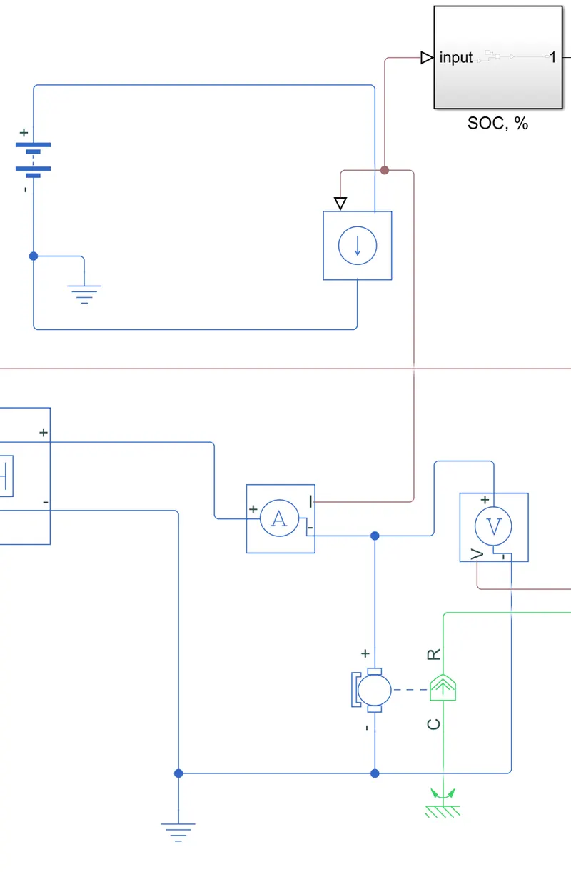
Current sensor is used to read the armature current and discharge a placeholder battery accordingly, for the SOC calculations.
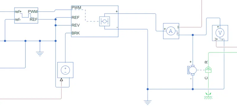
Following is the motor control architecture:
The motor is supplied by an H-bridge power converter. The Power converter is fed from a Controlled PWM voltage. The PWM block is powered by a controlled voltage source, which will be increasing/decreasing the voltage as per the intensity of acceleration.
H Bridge:
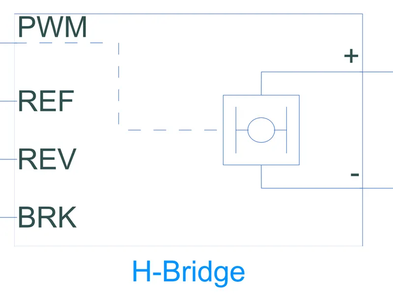
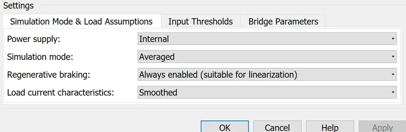
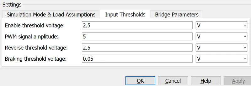
This block represents an H-bridge motor drive. The block can be driven by the Controlled PWM Voltage block in PWM or Averaged mode. In PWM mode, the motor is powered if the PWM port voltage is above the Enable threshold voltage. In Averaged mode, the PWM port voltage divided by the PWM signal amplitude parameter defines the ratio of the on-time to the PWM period. Using this ratio and assumptions about the load, the block applies an average voltage to the load that achieves the correct average load current.
For our model we will be using the Averaged mode as it leads to faster computing times.
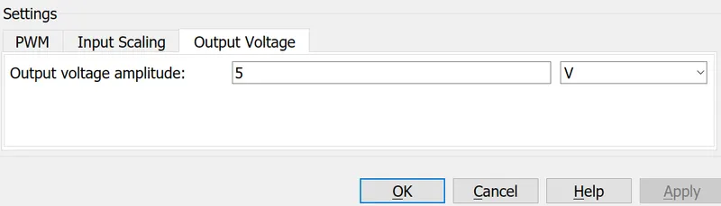
Controlled PWM voltage settings:
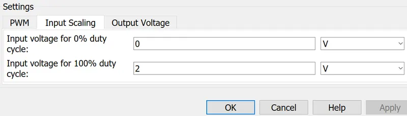
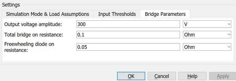
H bridge settings:
The controller system layout:
Drive cycle and Longitudinal driver:
Longitudinal driver:
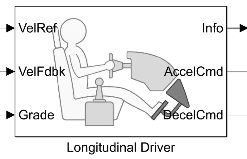
The longitudinal driver acceleration command feeds the controlled voltage source which will be powering the PWM block.
A similar signal is sent to the brake terminal of the H bridge from the deceleration terminal of the longitudinal driver.
The driver takes a Drive cycle reference as shown and outputs the commands comparing it with the vehicle feedback recieved from the vehicle body.
Appropriate PS-Simulink and Simulink-PS converters are used so that there is no incompatibility between the systems.
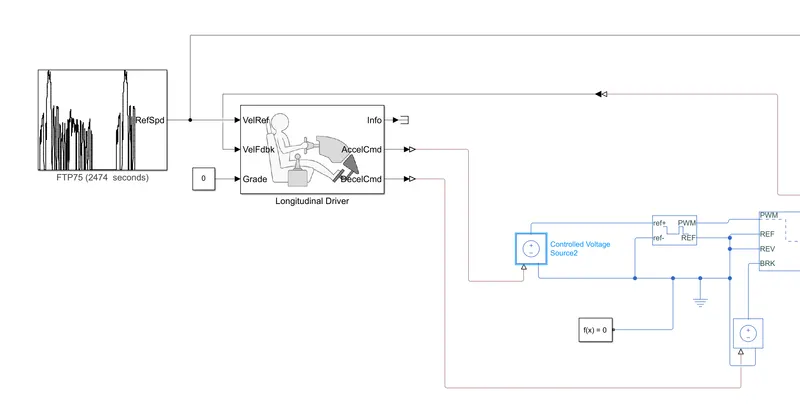
In our tests we will be using multiple drive cycles and analyzing the performance results. For our study we use the following drive cycle:
FTP75 : A standard drive cycle with large number of acceleration and deceleration commands and varying velocity range, typical of urban driving patterns
Battery pack:
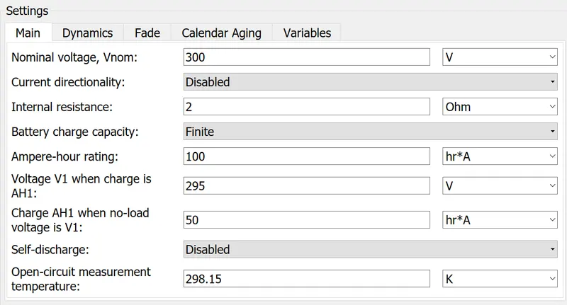
We will be simulating a battery supply by discharging an external battery equal to the armature current.
We will use a current sensor which will trigger a controlled current source for drainging the battery as shown:
Battery specifications:
SOC calculation block:
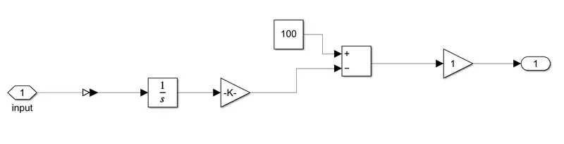
To calculate the instantaneous SOC, we integrate teh current wrt time to get A-s and divide by 3600 to convert it to Ah. This is subtracted from the battery capacity of 100 and then the percentage is displayed as the charge left.
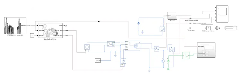
Complete EV model:
OUTPUT:
1. Drive cycle vs vehicle speed:
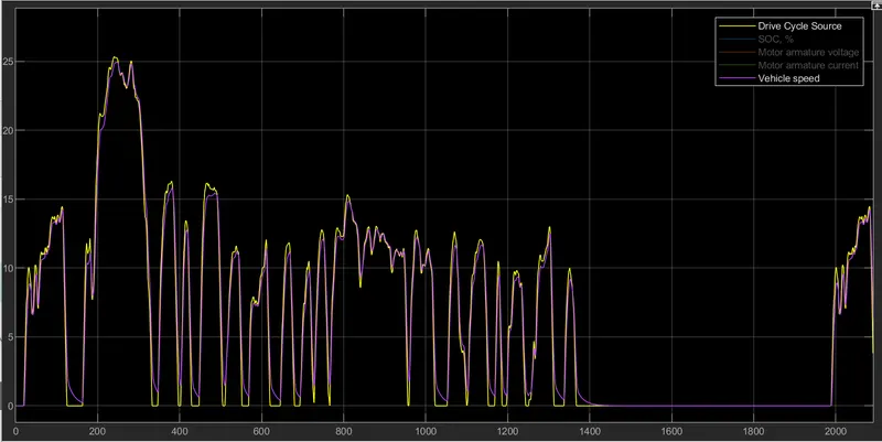
The vehicle reasonable matches the drive cycle, and the peak speed of 25 m/s is handled my the motor.
The system is not quite able to match the drive cycle during the deceleration, as the motor cannot handle the inertia at the high speeds. This can be fixed by increasing the motor power rating or making some compromise in the vehicle mass.
2. SOC ofthe battery:
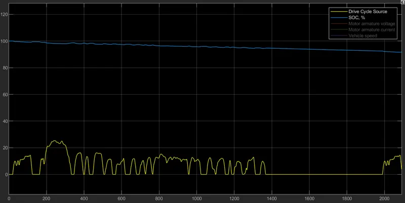
The battery is depleted to about 90% during the run.
3. Motor Armature Voltage:
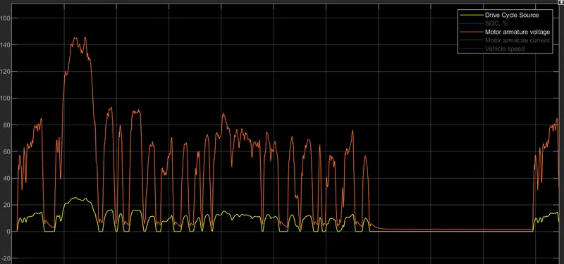
Motor armature voltage is directly proportional to the required speed. The voltage never goes negative, as there is no reversing in the drive cycle.
4. Motor armature Current:
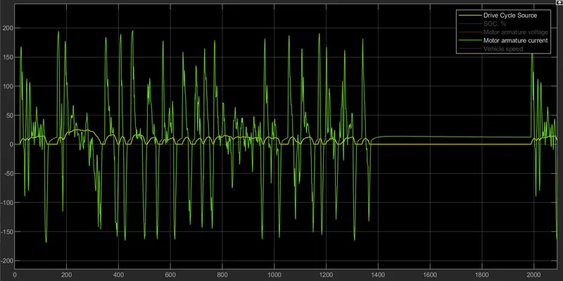
The armature current is positive during acceleration and negative during braking. The braking current, corresponds to the forward braking mode of the vehicle.
5. Distance covered:

The distance covered during the test is 17.88km
CONCLUSION:
Withing reasonable degree of accuracy, we have modeled a DC motor powered EV. Following conclusions can be drawn from the results:
1. The system is able to handle the top speed of the FTP75 drive cycle.
2. The vehicle is not able to decelerate quick enough due to its inertia. Reducing the vehicle mass can solve this problem.
3. The motor works well and regenerative action is present, indicated by the negative armature current and the SOC increasing during deceleration.
4. The 100Ah battery depletes by 10Ah over the duration of the test, and the distance covered is 17.88 km. This puts the range of the EV at about 178.8 km