Project-1: Powertrain for aircraft in runways
Part A:
1. Search and list out the total weight of various types of aircrafts.
A. Aircraft weights are classified into following:
i. Manufacturer's empty weight (MEW)
Also called Manufacturer's Weight Empty (MWE) or Licensed Empty Weight
It is the weight of the aircraft "as built" and includes the weight of the structure, power plant, furnishings, installations, systems and other equipment that are considered an integral part of an aircraft.
This excludes any baggage, passengers, or usable fuel.
ii. Zero-fuel weight (ZFW)
This is the total weight of the airplane and all its contents (including unusable fuel), but excluding the total weight of the usable fuel on board.
As a flight progresses and fuel is consumed, the total weight of the airplane reduces, but the ZFW remains constant.
iii. Maximum zero fuel weight (MZFW) is the maximum weight allowed before usable fuel and other specified usable agents (engine injection fluid, and other consumable propulsion agents) are loaded.
iii. Operating empty weight (OEW) (Roughly equivalent to basic empty weight on light aircraft)
It is the basic weight of an aircraft including the crew, all fluids necessary for operation such as engine oil, engine coolant, water, unusable fuel and all operator items and equipment required for flight but excluding usable fuel and the payload.
iv. Payload
It is the carrying capacity of an aircraft. It includes cargo, people, extra fuel. In the case of a commercial airliner, it may refer only to revenue-generating cargo or paying passengers.
v. Maximum takeoff weight (MTOW)
This is the maximum weight at which the pilot of the aircraft is allowed to attempt to take off.
vi. Regulated takeoff weight (RTOW)
Depending on different factors (e.g. flap setting, altitude, air temperature, length of runway), RTOW or maximum permissible takeoff weight varies for each takeoff. It can never be higher than MTOW. More information is on this answer.
vii. Maximum landing weight (MLW)
This maximum weight at which an aircraft is permitted to land.
The following image depicts takeoff weight components.
viii. Maximum ramp weight (MRW)
also called maximum taxi weight (MTW)
It is the maximum weight authorized for maneuvering (taxiing or towing) an aircraft on the ground.
ix. Aircraft gross weight
It is the total aircraft weight at any moment during the flight or ground operation. This decreases during flight due to fuel and oil consumption.
Below is a list of aircrafts with their respective Maximum Take off and Maximum landing weights:
| Sr. No | Aircraft | MTOW (kg) | MLW (kg) |
| 1 | Antonov An-225 | 6,40,000 | 591700 |
| 2 | Boeing 747-8F | 4,47,700 | 346091 |
| 3 | Boeing 747-8 | 4,43,613 | 306175 |
| 4 | Boeing 747-300[7] | 3,77,840 | 260320 |
| 5 | Airbus A340-500[8] | 3,71,950 | 240000 |
| 6 | Airbus A340-600[8] | 3,67,400 | 256000 |
| 7 | Boeing 777F | 3,47,800 | 260816 |
| 8 | Airbus A330-900 | 3,52,000 | 251500 |
| 9 | Boeing 777-300ER | 3,51,800 | 251290 |
| 10 | Boeing 777-200LR | 3,47,450 | 223168 |
| 11 | Airbus A340-300[8][9] | 2,76,700 | 190000 |
| 12 | McDonnell Douglas MD-11 | 2,73,300 | 185000 |
| 13 | Airbus A350-900 | 2,70,000 | 175000 |
| 14 | Ilyushin Il-96M | 2,70,000 | 195040 |
| 15 | McDonnell Douglas DC-10 | 2,56,280 | 183000 |
| 16 | Boeing 787-9[10] | 2,54,000 | 192777 |
| 17 | Boeing 787-10[10] | 2,54,000 | 201849 |
| 18 | Airbus A340-200[8][11] | 2,53,500 | 181000 |
| 19 | Ilyushin IL-96-300 | 2,50,000 | 175000 |
| 20 | Airbus A330-300[12][13] | 2,42,000 | 185000 |
| 21 | Airbus A330-200[12][13] | 2,42,000 | 180000 |
| 22 | Lockheed L-1011-500 | 2,31,300 | 166920 |
| 23 | Boeing 787-8[10] | 2,28,000 | 172365 |
| 24 | Boeing 767-300ER | 1,87,000 | 136080 |
| 25 | Concorde | 1,85,000 | 111100 |
| 26 | Airbus A300-600[14] | 1,63,000 | 138000 |
| 27 | Boeing 767-300 | 1,59,000 | 136078 |
| 28 | Airbus A310-300[14] | 1,57,000 | 124000 |
| 29 | Vickers VC10 | 1,52,000 | 151900 |
| 30 | Boeing 707-320B[15] | 1,51,000 | 97500 |
| 31 | Boeing 707-320C[15] | 1,51,000 | 112100 |
| 32 | Airbus A310-200[14] | 1,42,000 | 123000 |
| 33 | Airbus A400M | 1,41,000 | 122000 |
| 34 | Boeing 720B[16] | 1,06,000 | 79500 |
| 35 | Boeing 720[16] | 1,04,000 | 79500 |
| 36 | Tupolev Tu-154M | 1,04,000 | 80000 |
| 37 | Tupolev Tu-204SM | 1,04,000 | 87500 |
| 38 | Boeing 737-900 | 85,000 | 66360 |
| 39 | Boeing 737-900ER | 85,000 | 71350 |
| 40 | Boeing 727-200 Advanced[17] | 84,000 | 70100 |
| 41 | Airbus A321-100[18] | 83,000 | 77800 |
| 42 | Boeing 737-800 | 79,000 | 65320 |
| 43 | Boeing 727-200[17] | 78,000 | 68100 |
| 44 | Boeing 737-700 | 70,000 | 58060 |
| 45 | Airbus A320-100[18] | 68,000 | 66000 |
| 46 | Boeing 737-400 | 68,000 | 54900 |
| 47 | Boeing 737-600 | 66,000 | 54660 |
| 48 | Airbus A220-300 | 65,000 | 57610 |
| 49 | Boeing 717-200HGW | 55,000 | 47174 |
| 50 | Embraer 175[20] | 37,500 | 32800 |
| 51 | Bombardier CRJ900[21] | 36,500 | 33345 |
| 52 | Embraer 170[22] | 36,000 | 32800 |
| 53 | Bombardier CRJ700 | 33,000 | 30390 |
| 54 | Bombardier Q400 | 28,000 | 28010 |
| 55 | Bombardier CRJ200 | 23,000 | 21319 |
| 56 | ATR 72-600 | 22,800 | 22350 |
| 57 | Saab 2000 | 22,800 | 21500 |
| 58 | Embraer ERJ 145 | 22,000 | 19300 |
| 59 | ATR 42-500 | 18,600 | 18300 |
| 60 | Saab 340 | 13,150 | 12930 |
| 61 | Embraer 120 Brasilia | 11,500 | 11250 |
| 62 | BAe Jetstream 41 | 10,890 | 10570 |
| 63 | Learjet 75[23] | 9,752 | 8709 |
| 64 | Pilatus PC-24[24] | 8,300 | 7665 |
| 65 | Embraer Phenom 300[25] | 8,150 | 7650 |
| 66 | Beechcraft 1900D | 7,765 | 7605 |
| 67 | Cessna Citation CJ4[26] | 7,761 | 7103 |
| 68 | Embraer Phenom 100 | 4,800 | 4430 |
2. Is there any difference between ground speed and air speed?
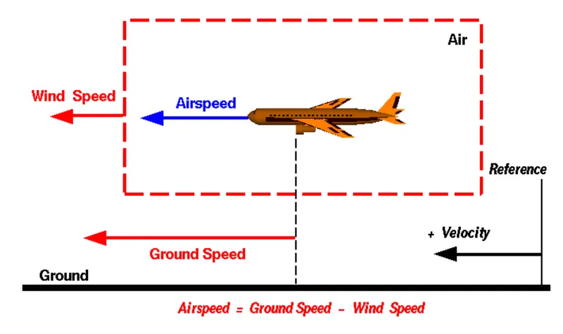
A. An Aircraft generates aerodynamic lift based on its speed relative to the wind speed. The greater the difference, the more the lift.
The aerodynamic lift varies as a swuare of this relative velocity. This velocity is known as "Air speed"
Ground speed is the velocity of the aircraft relative to a fixed point on the ground.
Thus Air speed can be vectorially defined as
Air speed = Ground speed - Wind Speed
3. Why is it not recommended to use aircraft engine power to move it on the ground at Airport?
A. i.. Aircraft engines are High power turbine that require a large warm up time in order to function effectively. A lot of fuel is spent in startup so that the engines are in smooth working condition and do not fail due to thermal stresses. Thus it is not fuel efficient to use aircraft engine to manuever the aircraft at an airport.
ii. A tow car can maneuver from the ground much more precisely than the pilot can from the aircraft cabin.
iii. The aircraft jets can be damaging to life and property.
iv. There is a risk of people and equipment getting sucked into the engine turbines while the engine is running.
Considering aboive reasons, Aircraft engines are generally not used on the ground, only during take offs.
4. How an aircraft is pushed to runway when its ready to take off?
A.
Large aircrafts utilise a pushback tractor or tug for pushing an aircraft to runway. Pushback tractors use a low profile design to fit under the aircraft nose. For sufficient traction the tractor must be heavy, and most models can have extra ballast added. A typical tractor for large aircraft weighs up to 54 tonnes (59.5 short tons; 53.1 long tons; 119,000 pounds) and has a drawbar pull of 334 kN (75,000 lbf). Often the driver's cabin can be raised for increased visibility when reversing and lowered to fit under aircraft.
Conventional tugs use a tow bar to connect the tug to the nose landing gear of the aircraft. The tow bar is fixed laterally at the nose landing gear, but may move slightly vertically for height adjustment. At the end that attaches to the tug, the tow bar may pivot freely laterally and vertically. In this manner the tow bar acts as a large lever to rotate the nose landing gear. Each aircraft type has a unique tow fitting so the towbar also acts as an adapter between the standard-sized tow pin on the tug and the type-specific fitting on the aircraft's landing gear. The tow bar must be long enough to place the tug far away enough to avoid hitting the aircraft and to provide sufficient leverage to facilitate turns. On heavy tow bars for large aircraft the towbar rides on its own wheels when not connected to an aircraft. The wheels are attached to a hydraulic jacking mechanism which can lift the towbar to the correct height to mate to both the airplane and the tug, and once this is accomplished the same mechanism is used in reverse to raise the tow bar wheels from the ground during the pushback process. The tow bar can be connected at the front or the rear of the tractor, depending on whether the aircraft will be pushed or pulled. The towbar has a shear pin which prevents the aircraft from being mishandled by the tug; when overstressed the shear pin will snap, disconnecting the bar from the nose gear to prevent damage to the aircraft and tug.
5. Learn about take off power, tyre design, rolling resistance, tyre pressure, brake forces when landing.
A.
Takeoff Power:
Takeoff power is the power required by an aircraft to take off the runway at a particular height.
To calculate the takeoff power, we will need to calculate the energy required for takeoff.
Consider an aircraft taking off a runway:
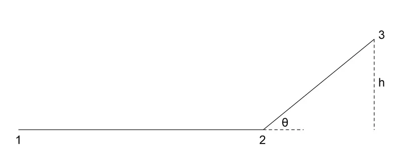
Pt. 1 is the starting point where velocity is 0.
Pt 2 is where the aircraft takes off.
Pt 3 is at a height of h from the ground.
Now to calculate the takeoff energy, we need to calculate the kinetic and potential energies at pt 3
At pt 3, KE = `frac(m*(v_3*costheta)^2)(2)` We take the horizontal component of velocity at point 3 since we are only supplying the horizontal velocity, and the vertical velocity is ahieved from aerodynamic lift.
Neglecting the air resistance between pt 2 and pt 3, we can safely assume that the horizontal component of velocity at pt 3 is equal to the velocity at pt 2
Thus At pt 3, KE = `frac(m*v_2^2)(2)`
PE = mgh
Thus the total energy required for takeff = `frac(m*v_2^2)(2)` + `m*g*h`
Power = E/t
Thus takeoff power = `frac(frac(m*v_2^2)(2) + m*g*h)(t)`
Tyre design:
Aircraft tyres operate under extreme conditions and hence are engineered to have high strength, durabililty and wear resistance. In addition to this, they can be repaired number of times under the process of retreading.
Tyres have to be carefully engineered and selected according to the application. There are following types of aircraft tyres:
Bias Ply:
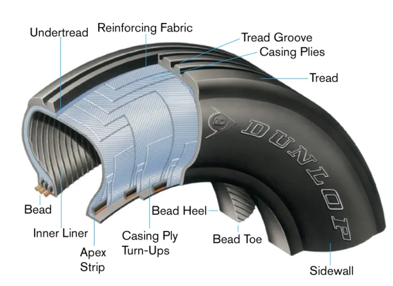
Tyres can be classified by the direction of the plies used in construction of the tire, either bias or radial. Traditional aircraft tires are bias ply tires. The plies are wrapped to form the tire and give it strength. The angle of the plies in relation to the direction of rotation of the tire varies between 30° and 60°. In this manner, the plies have the bias of the fabric from which they are constructed facing the direction of rotation and across the tire. Hence, they are called bias tires. The result is flexibility as the sidewall can flex with the fabric plies laid on the bias.
Radial Ply:
Some modern aircraft tires are radial tires. The plies in radial tires are laid at a 90° angle to the direction of rotation of the tire. This configuration puts the non-stretchable fiber of the plies perpendicular to the sidewall and direction of rotation. This creates strength in the tire allowing it to carry high loads with less deformation
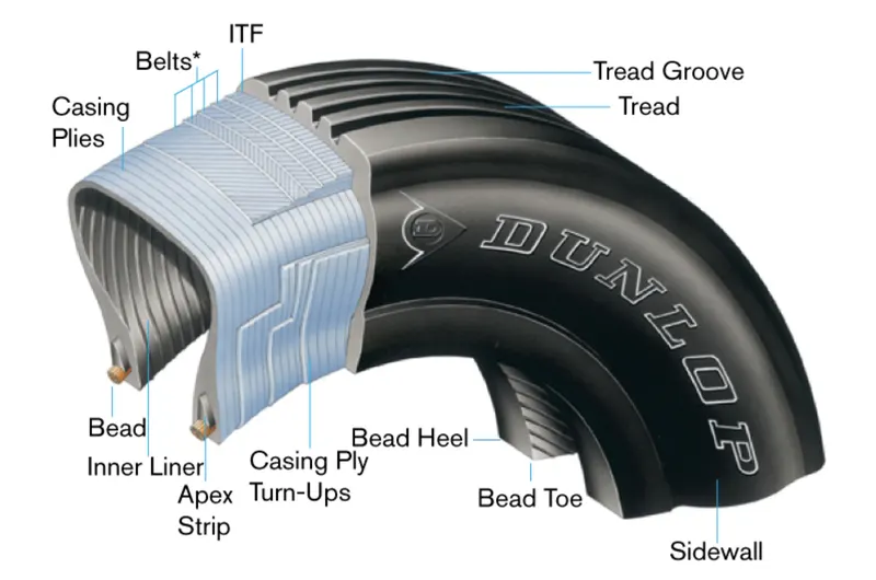
An overview of aircraft tyre ply components is shown below:
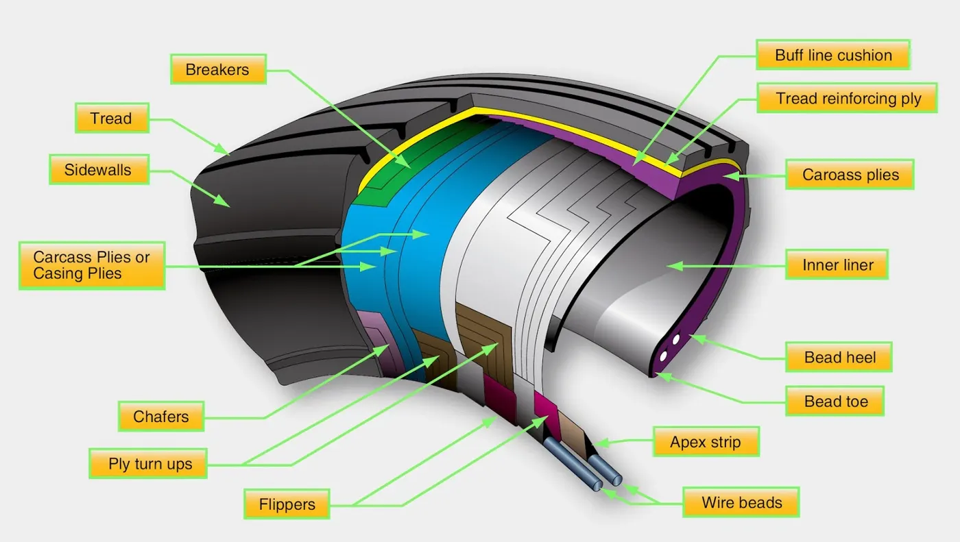
Apart from the ply, tyres can also be classified as tube or tubeless:
Tires that are made to be used without a tube inserted inside have an inner liner specifically designed to hold air. Tube-type tires do not contain this inner liner since the tube holds the air from leaking out of the tire. Tires that are meant to be used without a tube have the word tubeless on the sidewall. If this designation is absent, the tire requires a tube. Consult the aircraft manufacturer’s maintenance information for any allowable tire damage and the use of a tube in a tubeless tire.
Rolling Resistance:
Rolling resistance is the resistance to rolling motion. It depends on
co-efficient of rolling resistance between the material of the tyre and the runway,
mass of the aircraft
tyre pressure
For aircraft, rolling resistance comes into picture only during landing and take-off.
The rolling resistance can be calculated as follows:
FRR = `mu_(rr)*m*g`
To reduce runway losses, it is desirable to have a low rolling resistance.
Brake forces when landing:
An aircraft is immensely heavy and also moving at a high speed during landing. Thus the aircraft carries a large momentum, which has to be reduced to zero by braking. Thusaircraft brakes have to operate under extreme loads and hence are engineered to a very high degree of stability, thermal strength and wear resistance.
Let us assume an aircraft of mass m with velocity v, has landed on a runway of length L m. Lets calculate the braking force required to stop the aircraft within L m.
KE of the aircraft = `0.5*m*v^2`
Braking energy = `F_B*L` where `F_B` = total braking force
equating the above, we get `F_B = frac(m*v^2)(2L)`
As an example, for a Boeing 727-700, with a weight of 58000kg and a landing speed of 150 kmph,
we get a braking force of 50,351 N.
To achieve such high braking forces, specially designed aircraft brakes are used.
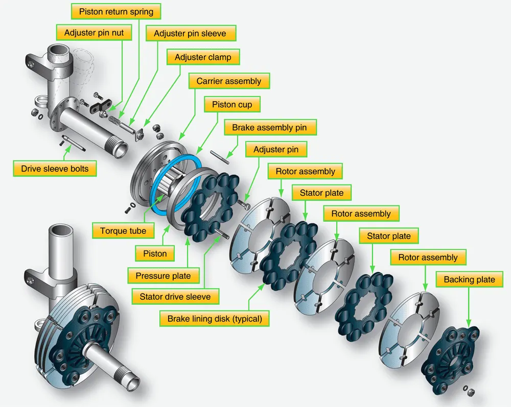
One of the advanced aircraft brakes is a segmented disc brake where the rotor assemblies are split into various segments which are then applied the braking force. This gives a much better force vs thermal stress performance compared to standard single disc brake:
6. A. With necessary assumptions, calculate the force and power required to push / pull an aircraft by a towing vehicle.
A. Lets assume the aircraft to be a Boeing 727-700, with a mass of m1= 58000kg.
Lets assume mass of the towing truck to be m2 =10000kg.
co-efficient of rolling resistance for aircraft tyres = `mu_(rr1)` = 0.002
co-efficient of rolling resistance for tow truck tyres = `mu_(rr2)` = 0.01
Lets assume that the air drag is negligible, since the towing is usually carried out at small speeds (<5m/s)
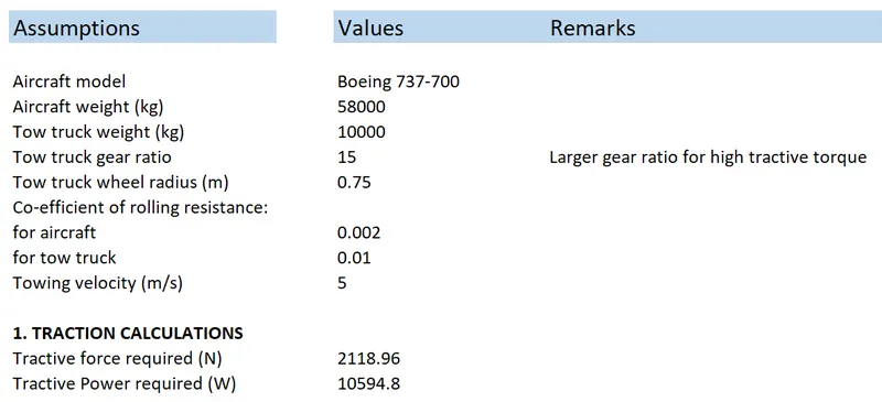
Force required for towing = `mu_(rr1)`*m1*g+`mu_(rr2)`*m2*g=0.002*58000*9.81+0.01*10000*9.81 = 2118.96 N
Following excel sheet calculator is used for the calculations:
6. B. Develop the model for the calculated force and power using Simulink.
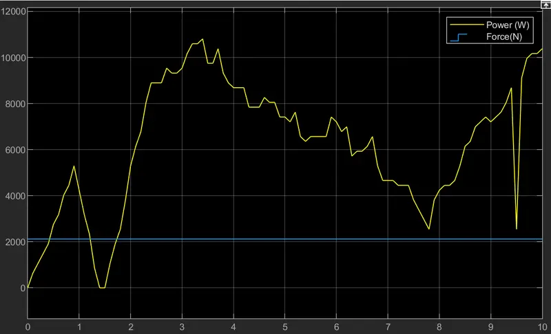
A. To calculate the force and power, we will be using a variable drive cycle for the velocity.
The block diagram is as shown below:
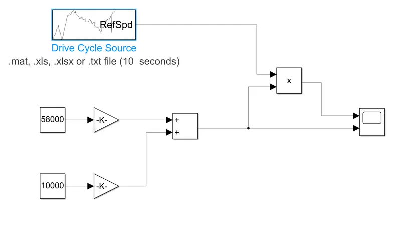
The forces on the aircraft and the tow truck are calculated by above equations and added together to get the total force which is one of the scope displays.
The total force is multiplied by the velocity from the drive cycle to get the power.
Output:
7. A. Design an electric powertrain with type of motor, it’s power rating, and energy requirement to fulfill aircraft towing application in Simulink. Estimate the duty cycle range to control the aircraft speed from zero to highest. Make all required assumptions. Prepare a table of assumed parameters. Draw a block diagram of powertrain.
A.
We will be using the same example as in Q.6.
Following excel calculator shows the motor selection calculations for satisfying the towing requirements:
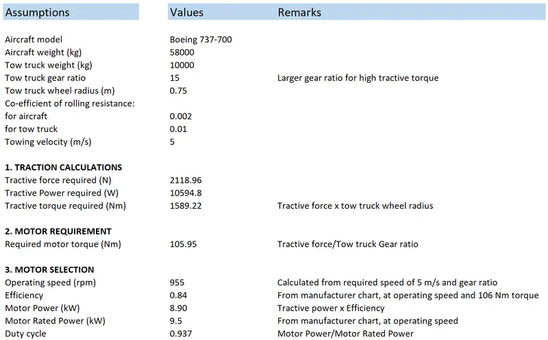
As per the motor torque and power requirement, we select the Boostech 42kW motor.
The motor parameters, taken from the manufacturer site are shown below:
We first calculate the operating speed of the motor.
Considering 5 m/s vehicle speed and gear ratio of 15, the operating speed comes out to be 955 rpm according to the excel calculator.
At 955 rpm, accordign to the motor charts, we get
Efficiency = 0.84
Rated Power = 9.5kW
Using these values we can get the duty cycle at max speed and power to be 0.937
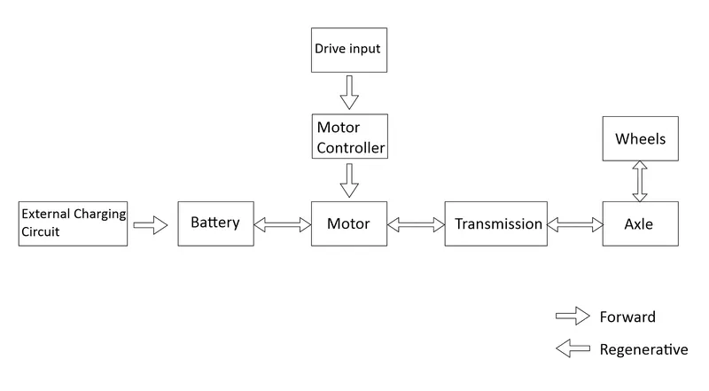
Block diagram of powertrain:
B. Also, Design the parameters in excel sheet.
The excel sheet calculator used for above example is shown below:
References:
https://en.wikipedia.org/wiki/List_of_airliners_by_maximum_takeoff_weight
https://www.dunlopaircrafttyres.co.uk/technical/
https://www.boostech.de/en/produkt/set-42-kw-electric-motor-160-nm-sevcon-gen4-size6-96v/