Week-7 Challenge: DC Motor Control
1. Run MATLAB demo ‘Speed control of a DC motor using BJT H-bridge’. Modify the model such that armature current doesn’t shoot up when motor changes direction from forward to reverse.
A. A BJT H-bridge is a circuit used to provide pulsating DC input to a DC motor, and to control its speed. The circuit is shown in the following figure: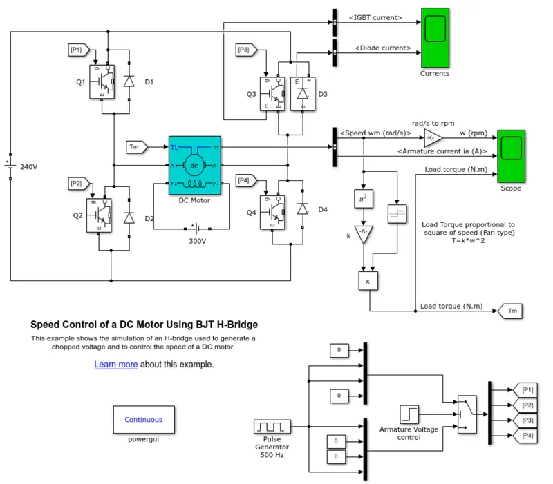
It consists of 4 BJT PNP thyristors connected to form an "H circuit" with the armature winding of the motor,such that Q1 and Q3 are conducting in one direction and Q2 and Q4 are conducting in the opposite. This forms the basis of the supply reversal of the motor.
The motor is externally excited by a field winding supplied with 300V.
The Thyristor pairs are controlled by a pulse generator which generates the gate pulses to excite the Thyristors.
The motor rotates in one direction when a thyristor pair is conducting, and when the thyristor pair is changed, the motor reverses direction.
Each of the thyristors have a freewheeling diode in parallel to dissipate any energy generated by the motor.
1. Running the original simulation
Running the simulation yields the following result:
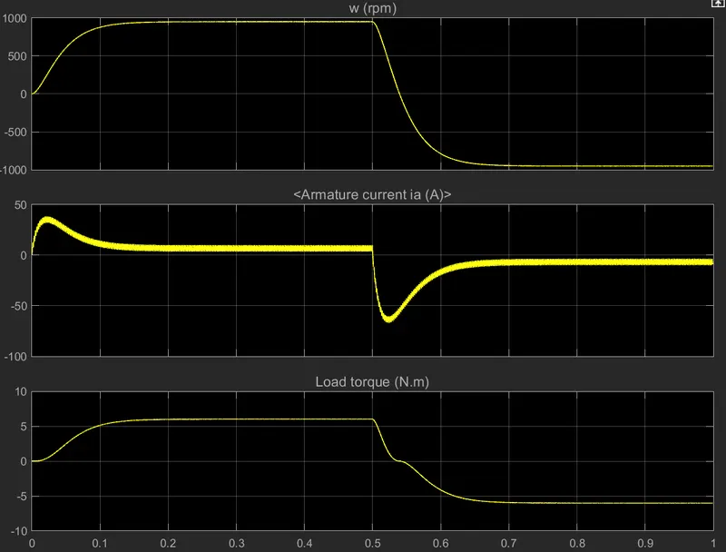
We can see that during starting, or during braking of the motor, the armature current shoots up.
This can be controlled by following methods:
1. Increasing inductance of armature windings.
2. Reducing duty cycle of the control BJTs
Since the motor model is predefined, we will be using the second method to control the current spikes.
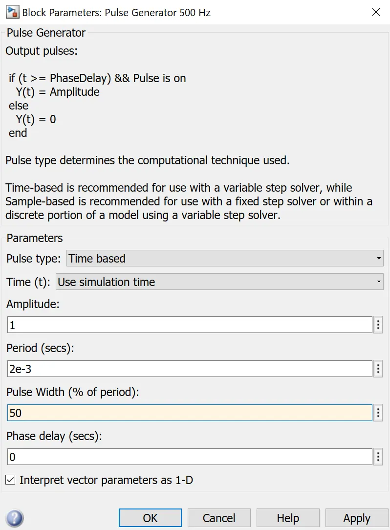
We reduce the duty cycle of the BJTs from 75% to 50% as shown:
When the simulation is run, we get the following result:
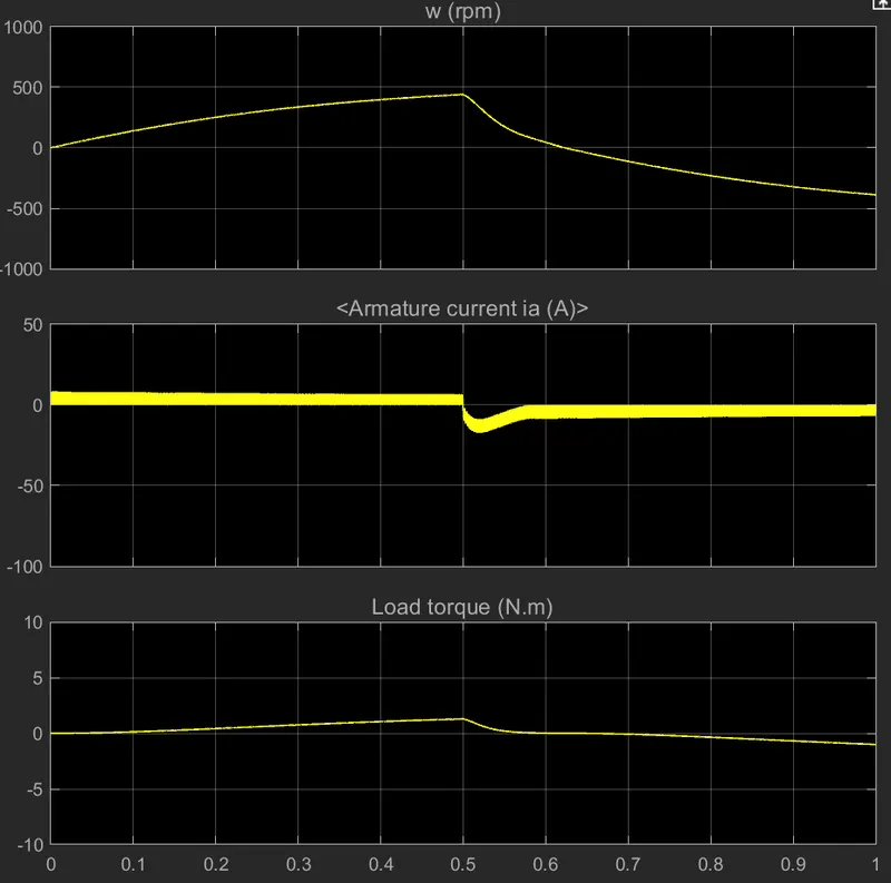
Thus we have reduced armature current spike from about 65A to 20A, at the cost of reduced max speed.
2. Refer to help section of ‘The Four-Quadrant Chopper DC Drive (DC7) block’. Compare it with H-bridge model.
A. The four quadrant chopper DC drive consists of an externally excited DC motor, supplied with an armature voltage of 515V after rectification of 380V AC supply. The armature voltage is supplied by a IGBT converter, controlled by two PI reguulators, a speed regulator and a current regulator.
The speed regulator outputs the current reference required to attain the reference speed, while the current regulator takes the current reference as input and controls the armature current accordingly.
The current regulator determines the duty cycle of the four IGBT devices, and generates the average voltage needed for the armature current.
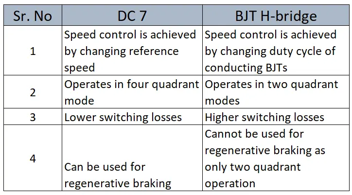
Comparison of Four quadrant chopper DC drive block and BJT H-bridge:
3. Make a suitable EV model using DC7 block and make result report.
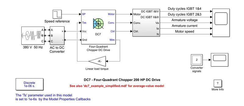
The Simulink DC block consists of a 4 quadrant DC chopper block, which is fed a speed reference. A 380V 50Hz ac supply is rectified and input to the chopper.
The armature voltage is supplied by a IGBT converter, controlled by two PI reguulators, a speed regulator and a current regulator.
The speed regulator outputs the current reference required to attain the reference speed, while the current regulator takes the current reference as input and controls the armature current accordingly.
The current regulator determines the duty cycle of the four IGBT devices, and generates the average voltage needed for the armature current.
To use the above model in an EV we need to
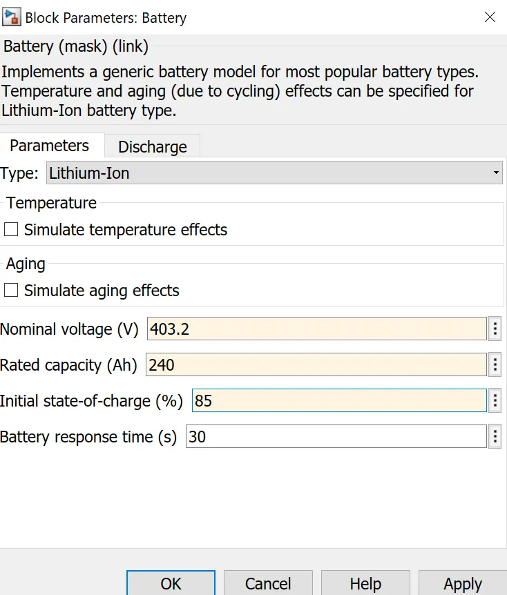
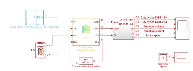
i. replace the AC supply and rectifier with a constant voltage DC source.
We use the following parameters for the battery. These are typical parameters of EV battery packs:
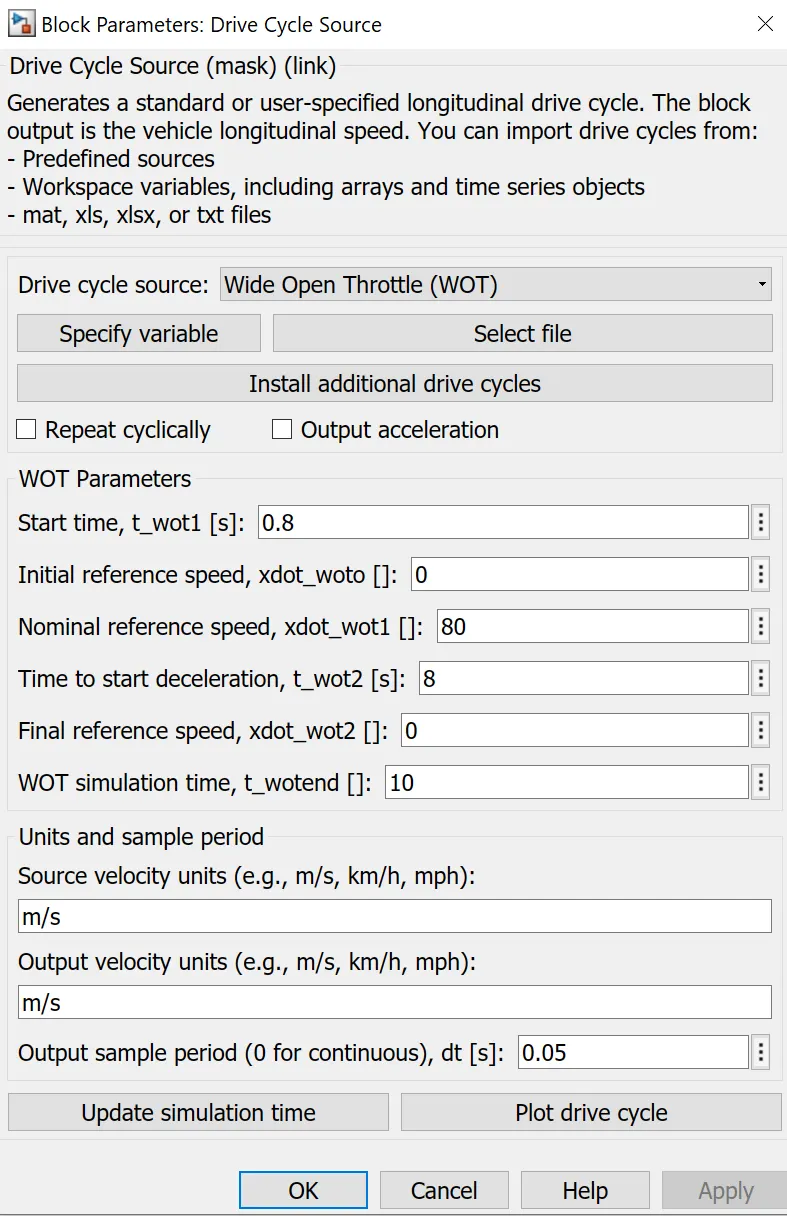
ii. Give a WOT cycle as the speed reference
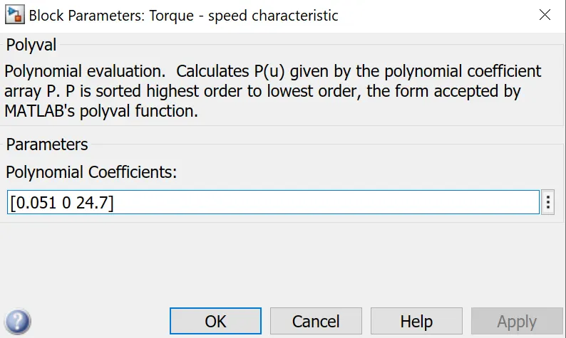
iii. Give the following Torque - speed characteristics to the motor block:
T = 24.7 + 0.051`omega^2`
We implement the above equation using a polynomial block:
Final model:
We get the following output after running the simulation:
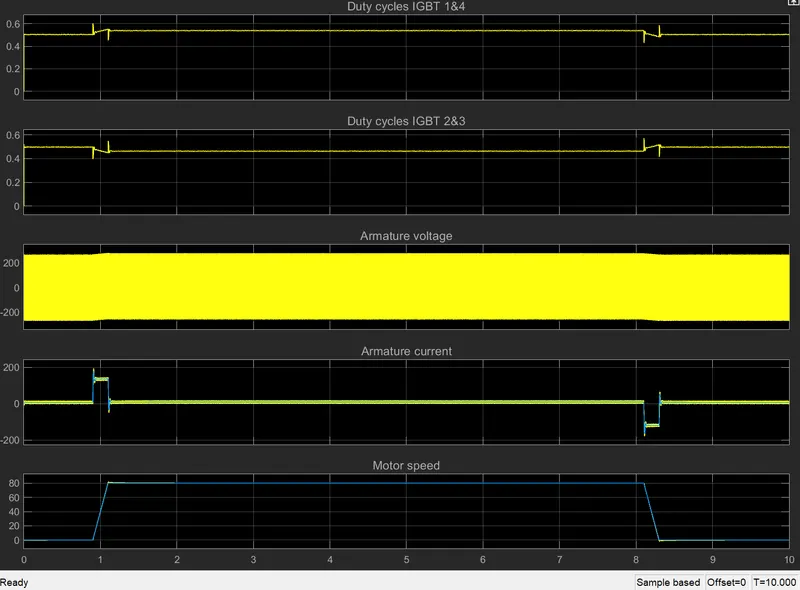
Fron t=0s to t=0.8s, the motor is in standby condition and armature current is zero.
As the speed reference changes according to the drive cycle, the duty cycle of IGBT 1and 4 increases and that of 2 and 3 decreases. This gives positive armature current and hence the motor speed starts increasing till it reaches the desired speed.
At t = 1.1s, the speed stabilizes and the duty cycles of the IGBTs go back to default 0.5.
At t=8.1s, the speed starts reducing, and the IGBT duty cycles reverse as compared to during the acceleration phase, and armature current goes negative.
At t=8.3s the reference and motor speed reaches zero and the IGBT duty cycles default back to 0.5
Thus the motor is modeled for the WOT cycle with a generic battery source.
4. Explain in a brief about operation of BLDC motor.
A BLDC motor operates on the principle of Force acting on a current carrying coil in a magnetic field.
By using several coils rotating freely on a central axis and changing the direction of the current constantly, the resultant force can be in the desired direction. Thus electrical energy is converted into mechanical rotational energy.
The magnetic field may be generated by Permanent magnets, or it can be from electromagnets which are externally excited by field windings.
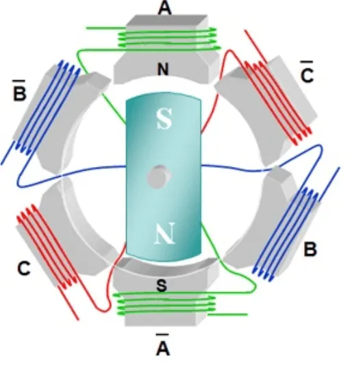
Shown above is a simplified PM BLDC motor
The stator carries the armature windings that carry a pulsating DC current supplied by DC-DC converters like BJT H-bride or DC-7 IGBT converter.
The DC source for the converter is taken from the EV battery.
Due to the armature current, the coils experience a force due to Lenz's law. The equal and oppsite force is felt by the permanent magnet, which rotates so as to negate the force. The armature current keeps switching between the stator windings, so as to keep the magnet, and hence, the totor, rotating constantly.
Depending on the converter, the motor can work in two quadrant or four quadrant mode.