Assignment 6-Frontal Crash Simulation Challenge
OBJECTIVE:-
To Simulate the Frontal crash analysis of the model given model to obtain sectional force in the rails, axil force received on the rails from the bumper, shotgun cross-sectional forces, A-pillar cross-section & acceleration curve received on the accelerometer at the base of B-pillar(on B pillar rocker) and intrusion on the dash wall.
Significance: A car's frontal area facing the oncoming air is designed with effective aerodynamics. Given the high likelihood of front-end collisions, such impacts result in significant deformation in the frontal region of the vehicle. The primary goal in assessing frontal crashes is to evaluate the potential safety and injury risks for drivers and passengers.
PROCEDURE:-
Step-1:
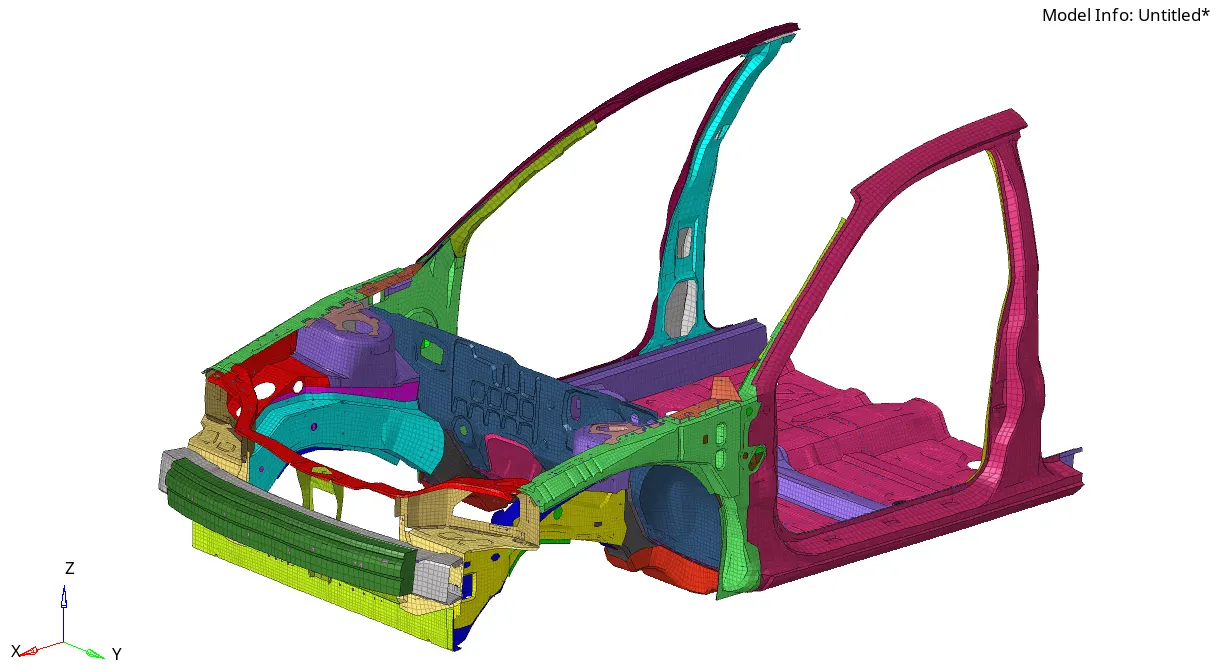
Import the neon_front_0000.rad model & check down the unit system it follows.
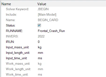
So it is following the Kg, mm, ms Unit system.
Step-2: Create the appropriate interface, friction 0.2, and recommended parameters.
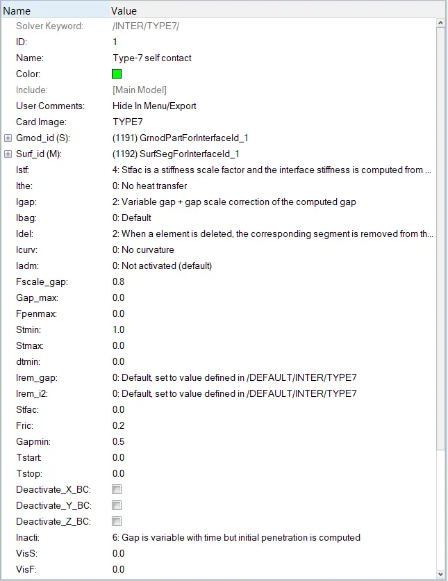
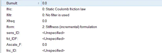
Contact created for total model.
Now, Penetrations need to be checked down after applying contact to the components.
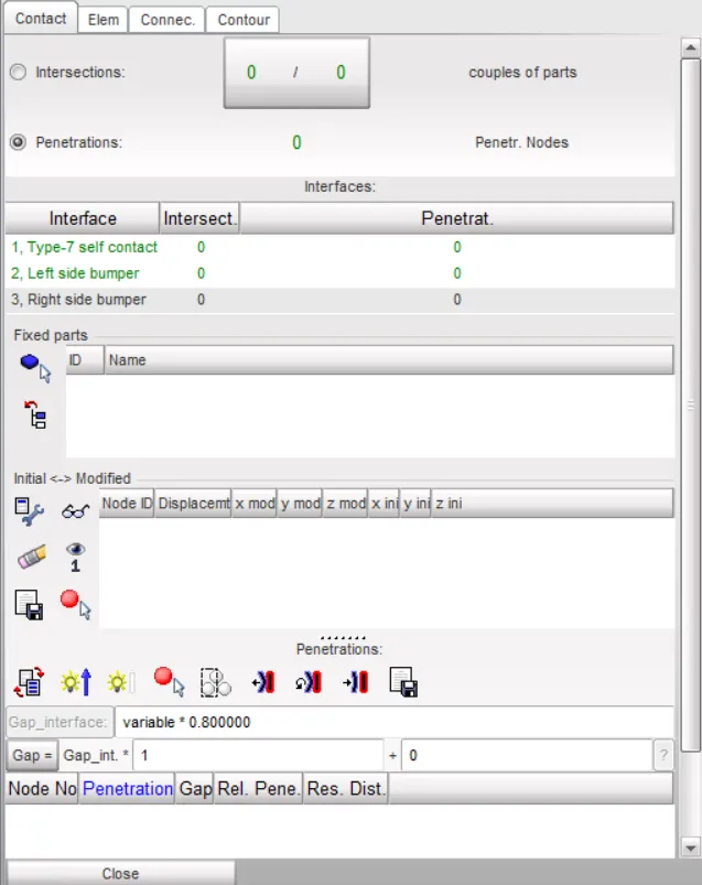
No actions are required for the penetrations.
Step-3:
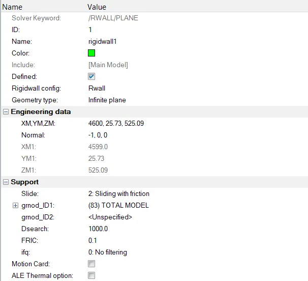
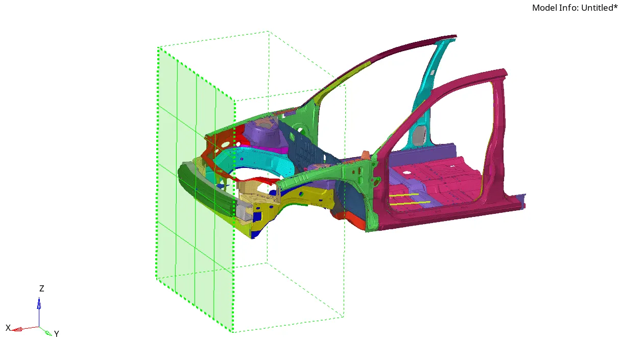
Creation of rigid wall with 0.2 friction.
Step-4:
Compare the model weight with the full-scale 300k nodes model and use added masses to reach a target weight of 700kg while getting CG about the required range.
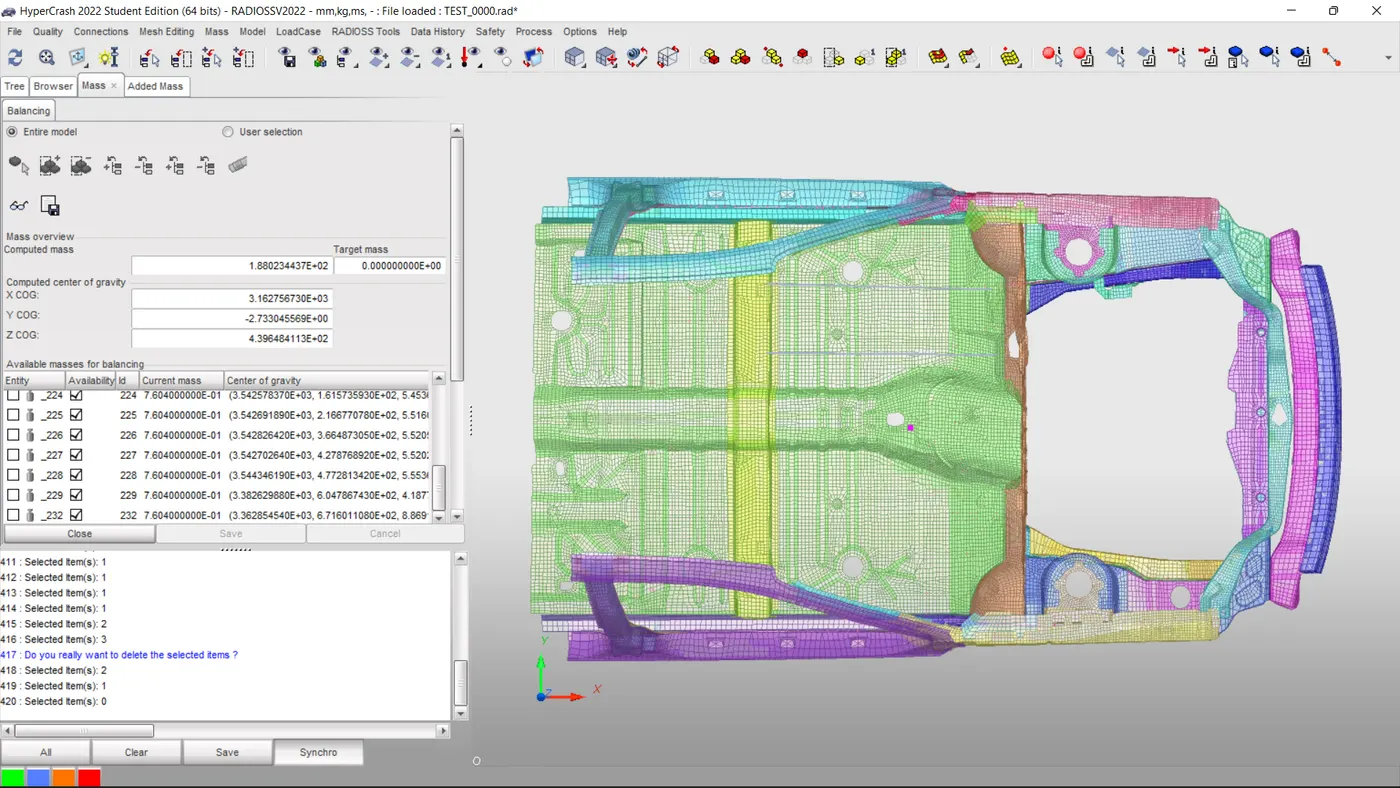
Now the mass is added to the floor panel to around 700 kgs.
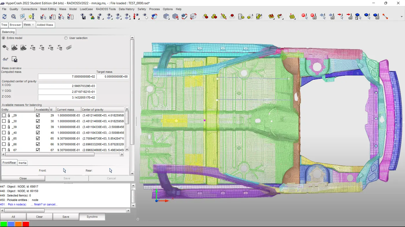
The Center Of gravity is adjusted to set at the middle portion where the sitting position of the driver is.
Step-5:
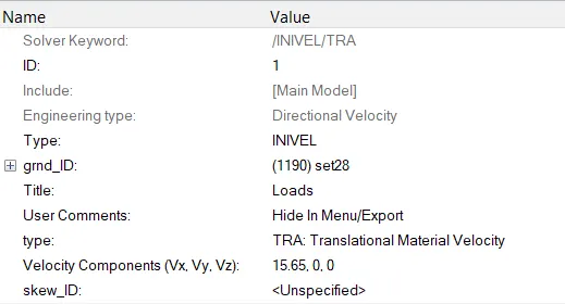
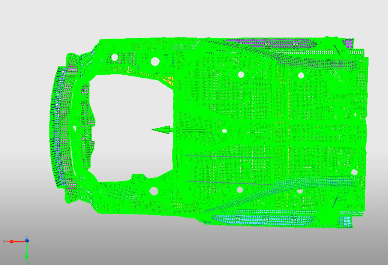
Given an initial velocity of 35MPH (15.6464mm/ms) in a positive x-direction.
- Step-6:
- To know the sectional force Of A-pillar, Shot-guns, and Rails we need to create sections.
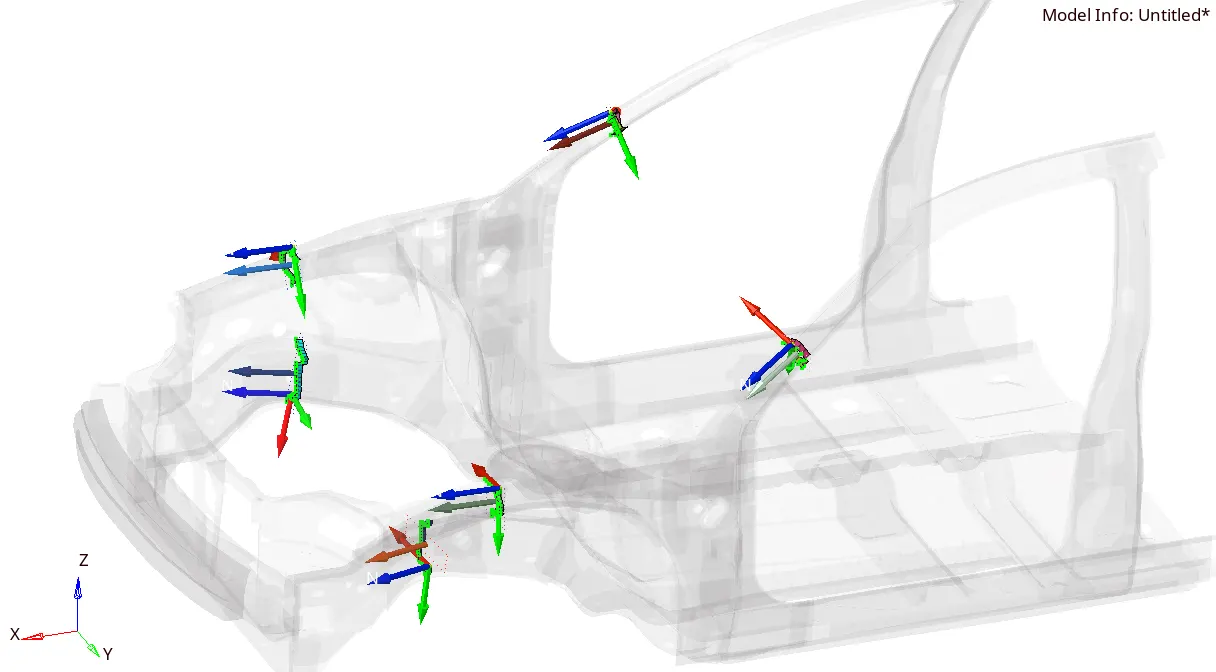
- We need to create MOV frames and sections to achieve the target force recordings.
Step-7:
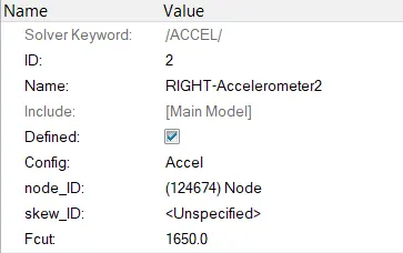
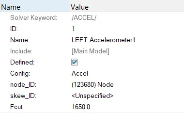
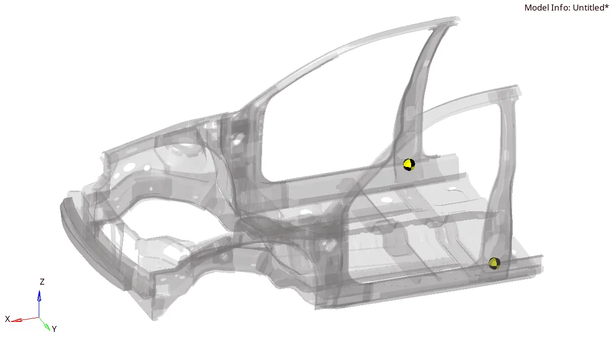
To record acceleration on the base of B pillar (B pillar rocker).
- Step-8:
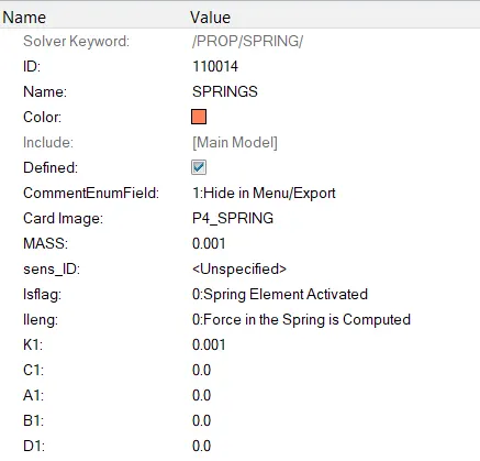
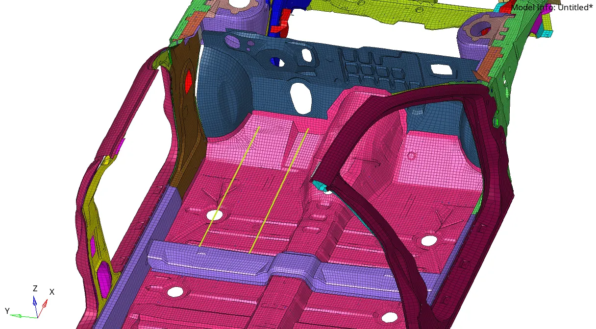
To know the instructions on the dash wall I created 2 springs.
Step-9:
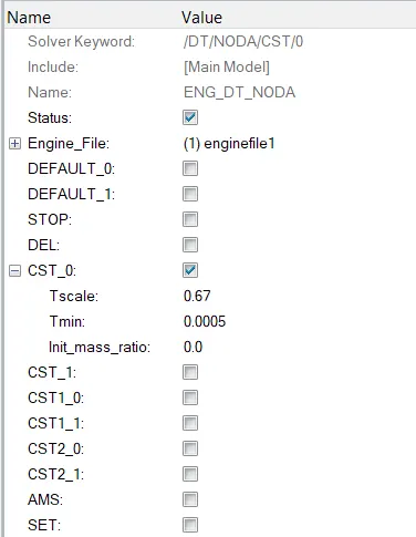
We need to set the minimum time step to 0.5 microseconds.
Step-10:
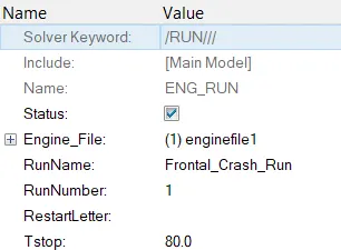
Simulating for 80 ms as mentioned the value is set down.
Step-11:
So before doing simulation after setting all kinematics conditions, we need to run the model checker to correct the issues for proper simulation.
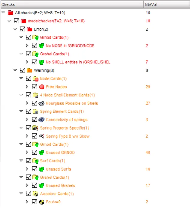
There are some errors and warnings that need to be checked.
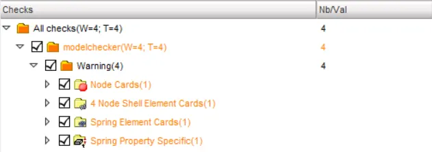
All the Errors are been cleared and some warnings of unused cards have been deleted.
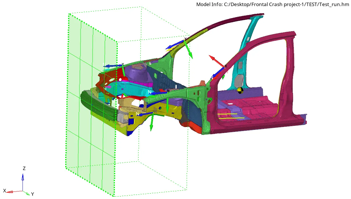
Now we are ready to simulate.
Results:-

- Energy error is in the range of 0 to -2.7% which is acceptable (-2.7% > -15%).
- The mass error starts from 0.9771E-04 and increases till 0.1193E-02 (Mass error range of 1-3%).
- The time step is constant throughout the simulation at 0.5ms
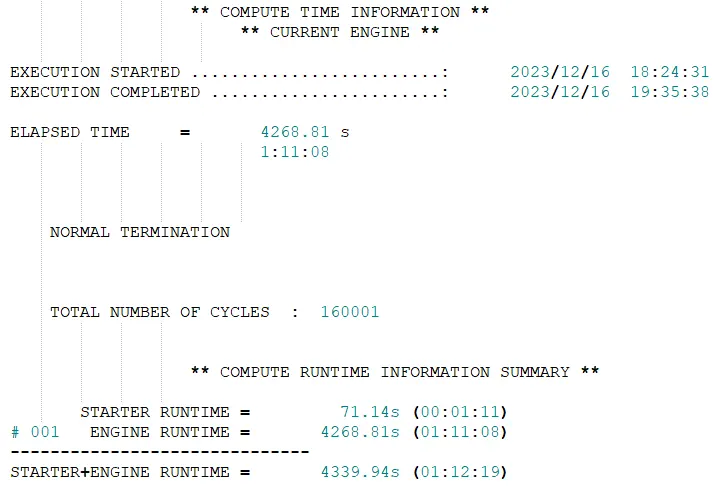
- NORMAL TERMINATION message is displayed at the end of the file
- The total simulation time is about 4268.81 s around 1 hr 11 min 8 seconds.
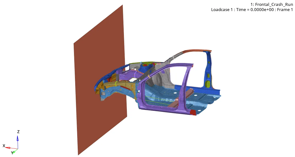
STARTING OF SIMULATION:
END OF SIMULATION:
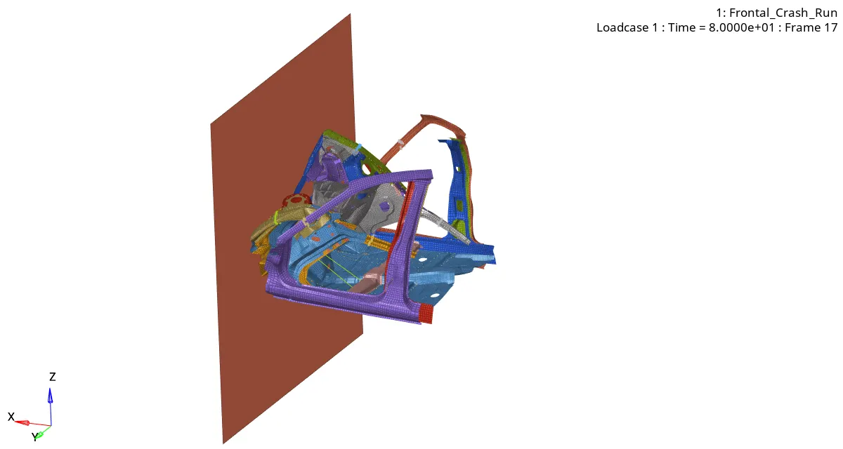
RAIL'S:-
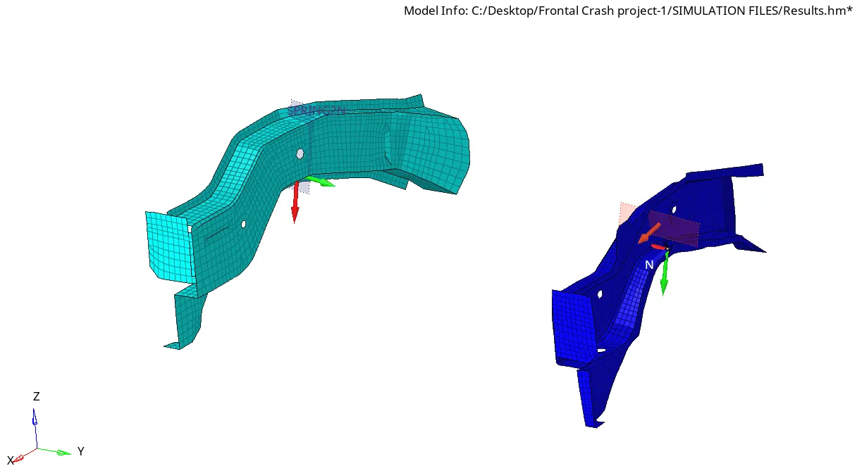
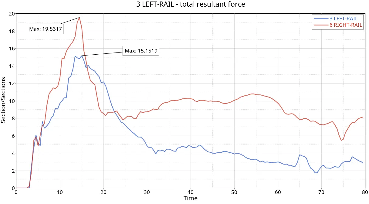
For the rails, the Right Rail received the maximum amount of force of 19.5317 KN & Left Rail received 15.1519 KN.
A-PILLAR'S:-
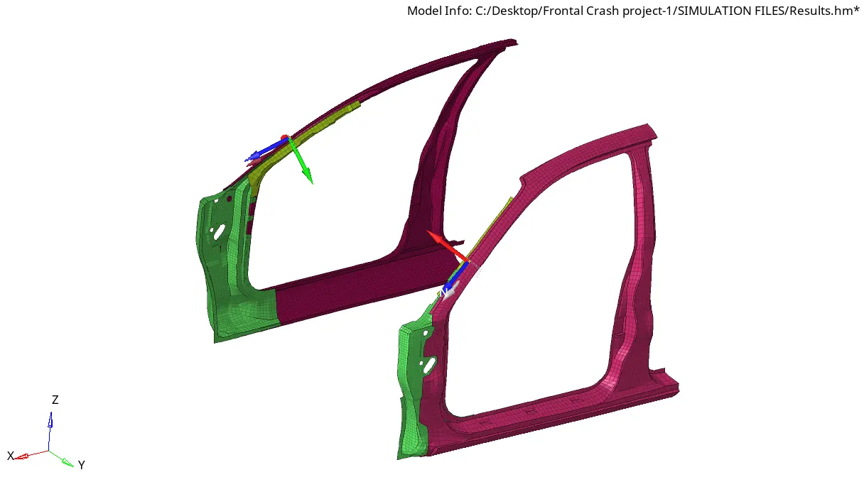
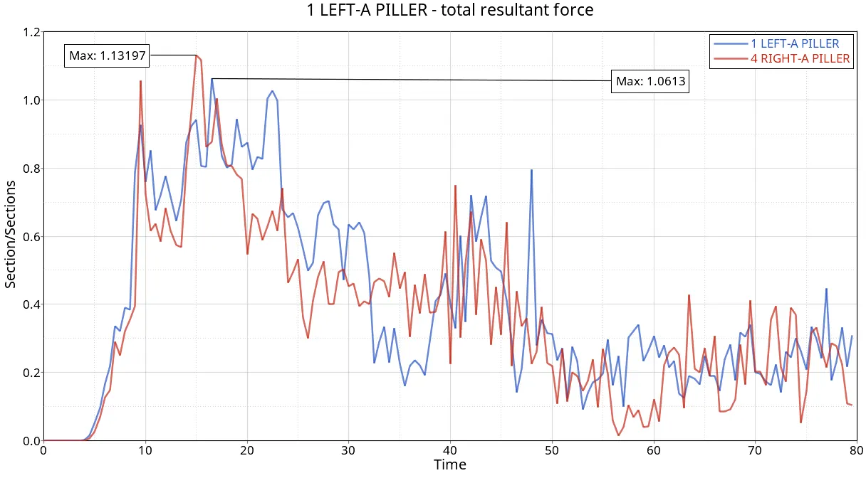
For A-pillars, the Right side received the maximum force of 1.13197 KN & on the Left side, 1.0613 KN was received.
SHOT-GUN'S:-
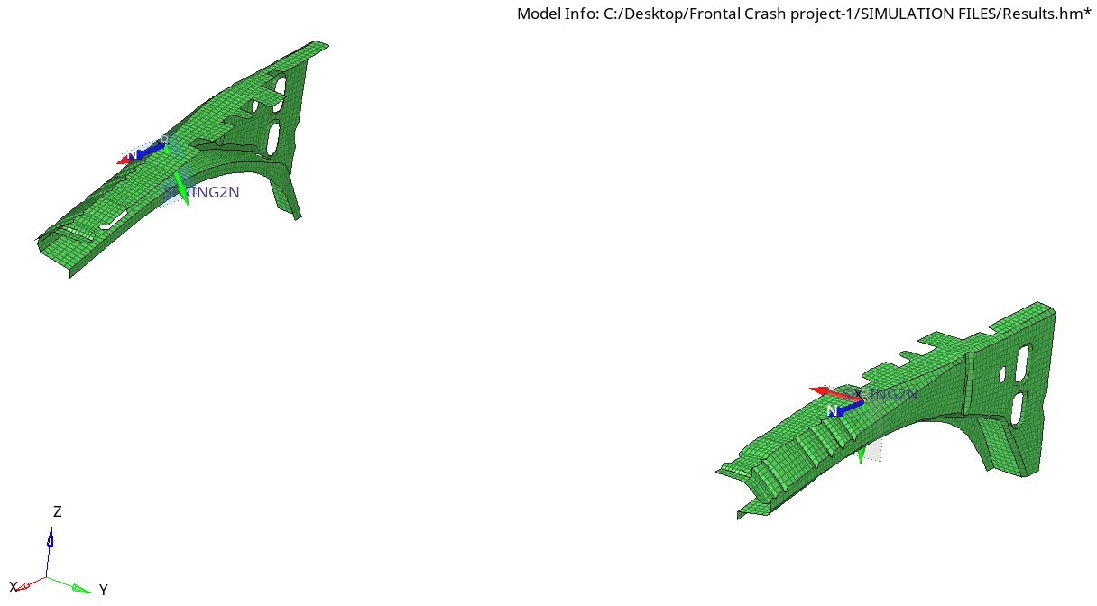
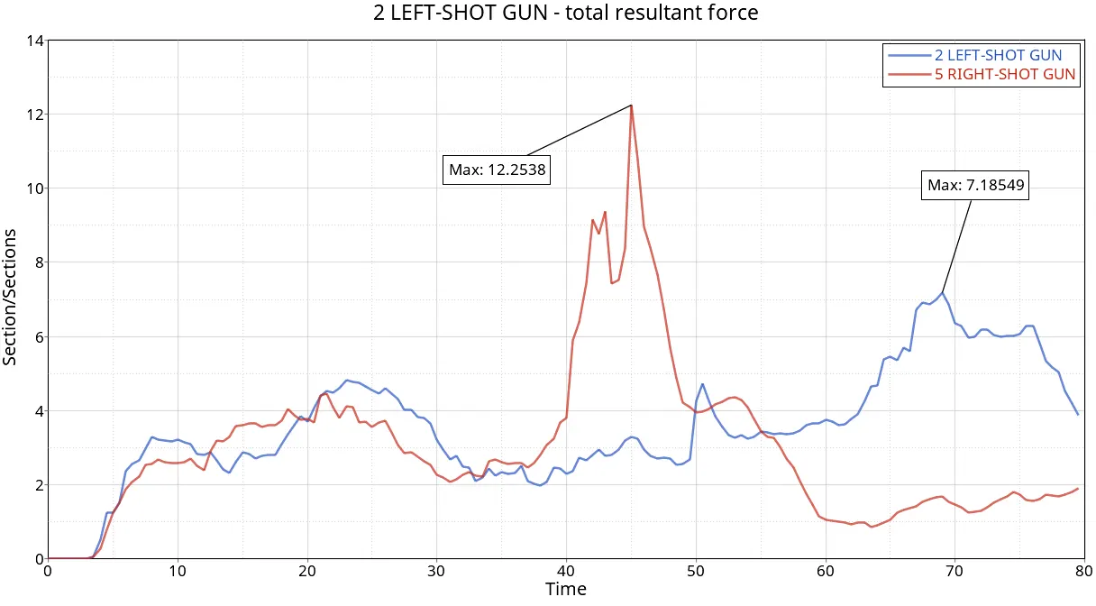
We observed that the Right-side shotgun received the maximum force of 12.2538 KN & Left-side shotgun received 7.1854 KN.
HEADLIGHT BRACKETS & BUMPER:-
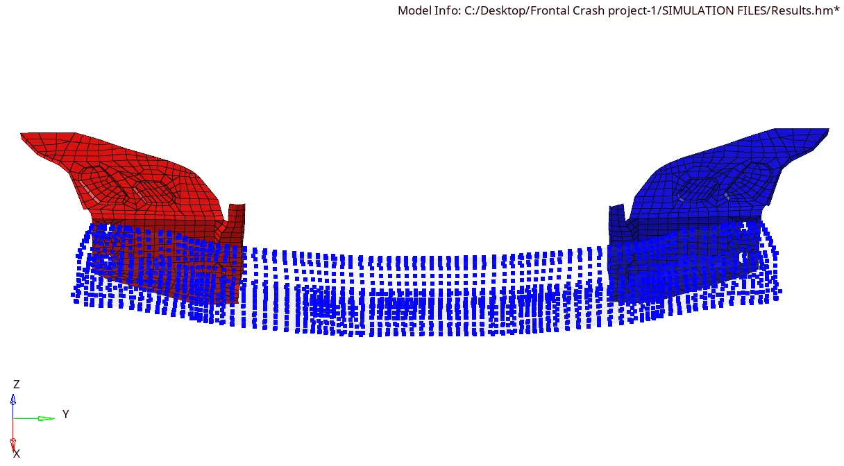
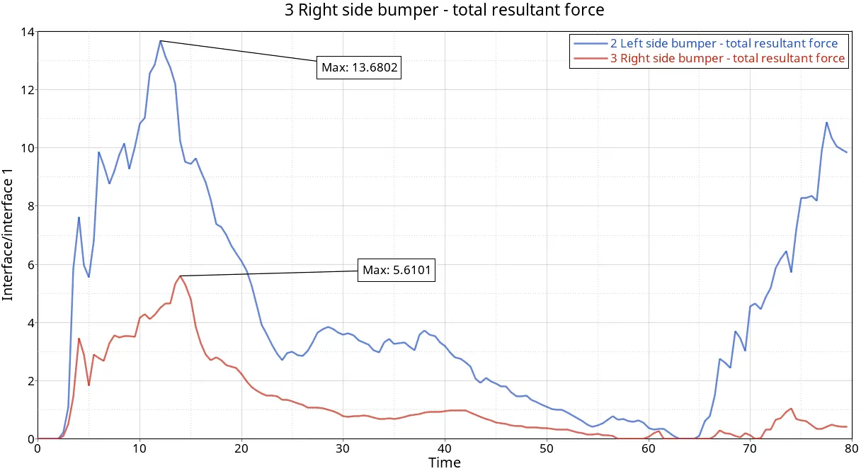
The Left side bumper received a maximum amount of force of 13.6802 KN & on the Right side Only 5.6101 KN.
ACCELEROMETER:-
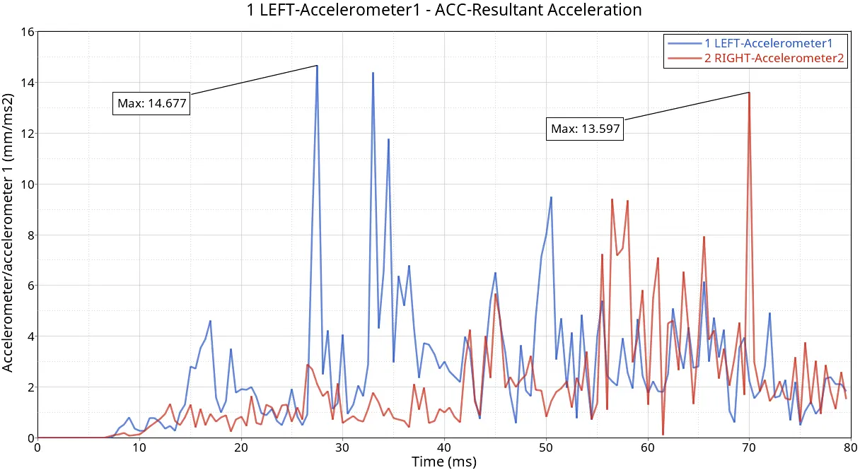
Here the Left pillar has maximum retardation of 14.677 m/s^2 & on the Right side, it recorded a max at the value of 13.597 m/s^2.
INTRUSIONS:-
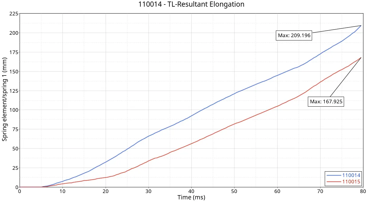
We can see on the dash wall there is a deformation of 167. 925mm - 209.196 mm.
GLOBAL-VARIABLES:-
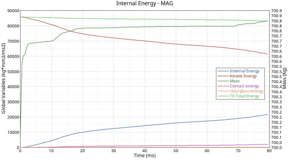
Total kinetic energy is converted into internal energy but some errors in total energy due to a slight increase in contact and hourglass energies. Where mass is being added to the elements for which the time step reached below 0.5 microseconds, by adding mass to those small time step elements the density increases which results in the decrease of the speed of sound so that the time step will increase in this way the correction will happen. Here that total mass added is 0.8351 kg which is very minimal.
VON-MISSES STRESS:-
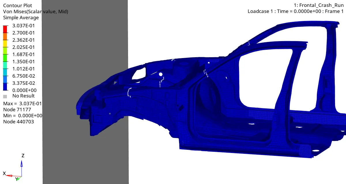
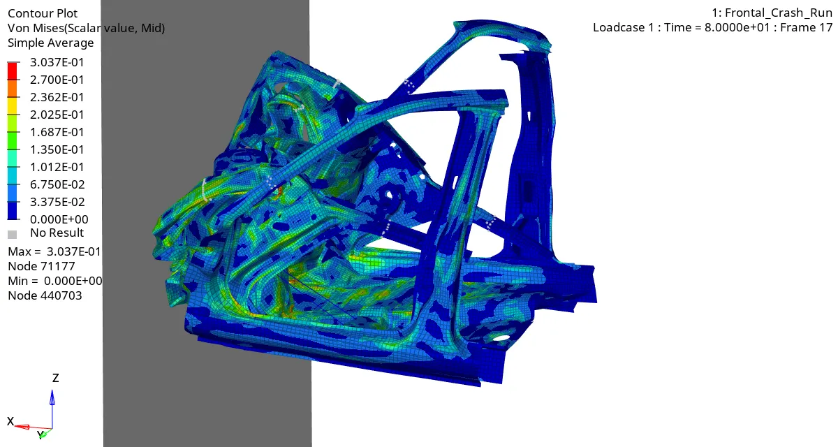
During the simulation the maximum amount of Von-Misses Stress noted is 3.037E-01 Gpa.
CONCLUSION:-
From this analysis, I learned how to plot the results of the cross-sectional forces, how to set the kinematic conditions like a rigid wall, initial velocity, and mass balancing, penetrations checking in interfaces, how to deal with the model checker & how to request outputs.
By observing the energy plots we can clearly say that the energy is getting distributed from the point of the collision with the Rwall, the forces getting distributed from bumper to rails to shot-guns to pillars which is required for the safety of the passengers in the vehicle.