Project-2-Meshing of Door Inner Panel Challenge
AIM:
TO MESH THE GIVEN COMPONENT IN THE TASK WITH THE TARGET ELEMENT SIZE.
Elements Quality Criteria:
Target Element Length = 4 Units
| S.N | Quality Criteria | Value |
| 1 | Aspect Ratio | 5 |
| 2 | Skewness | 45 |
| 3 | Warping | 15 |
| 4 | Taper | 0.5 |
| 5 | Min. Length | 2 Units |
| 6 | Max. Length | 6 Units |
| 7 | Min angle Quad | 45 |
| 8 | Max angle Quad | 135 |
| 9 | Min angle Tria | 20 |
| 10 | Max angle Tria | 120 |
| 10 | Tria % | 10 |
Procedure To Accomplish The Given Task:-
Step 1:-
We have to Download the model and import it into Hypermesh software.
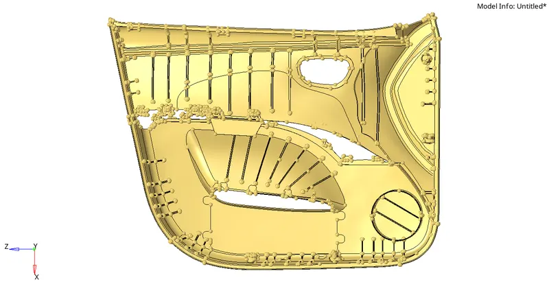
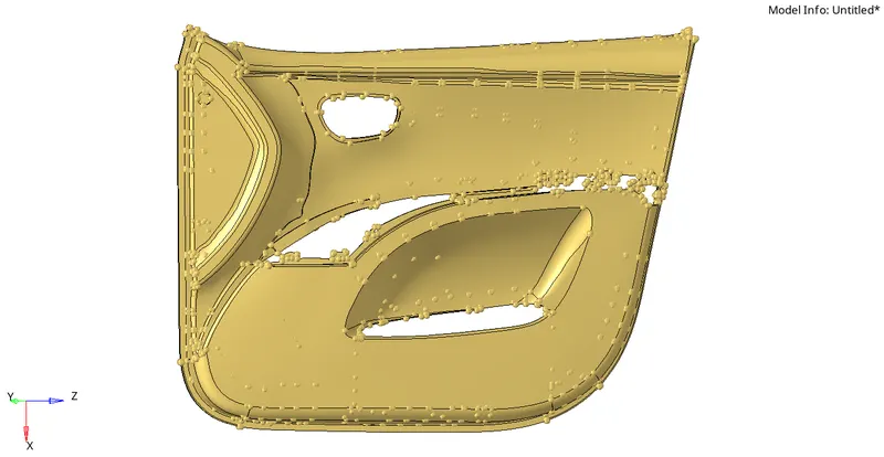
Step 2:-
By checking the given model in topo mode and in the wireframe mode confirming no mistakes or errors in geometry we can make a mid-surface.
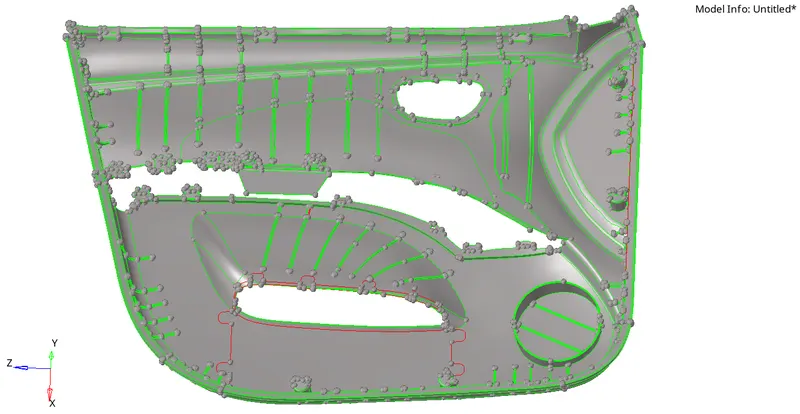
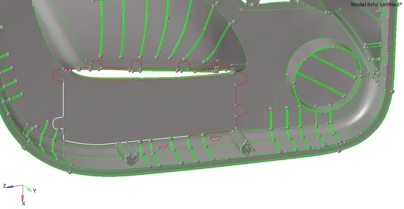
We can see some surfaces missing in the parent geometry which can lead to improper mid-surface, so we need to be very care full in clearing these types of big geometrical errors, we have to do corrections in parent geometry only to get good mid-surface as much as we can.
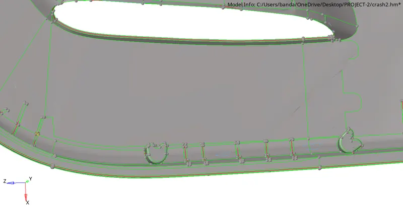
Here I had formed a new surface as we need without any errors.
Step 3:-
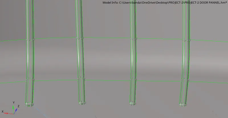
We need to defeature in this kind of situation to get a better mid-surface in these small regions.
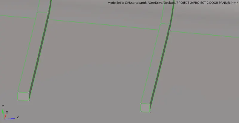
In this way, I cleared these types of small filleted regions.
Step 4:-
As mentioned in the guidelines I also followed the instructions given to do in some regions.
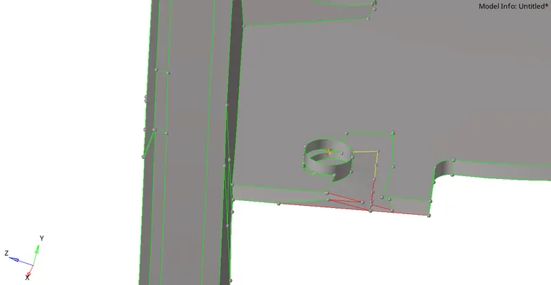
See here how the surface is in such an improper way.
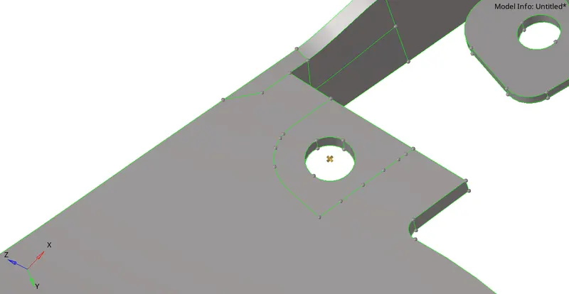
So I worked on here to create a proper surface which is a good sign for taking mid-surface as we assumed without any errors.
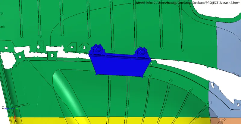
Here the blue component is not having any proper attachment so as mentioned in the guidelines I got created a new collector and I separated it by sending this part to that collector.
Step 5:-
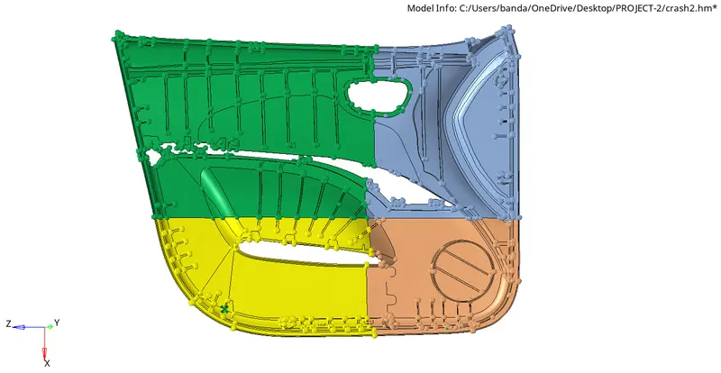
So I have done all the corrections required to do in the parent geometry and I also separated the parent component into 4 halves to start making the mid-surface.
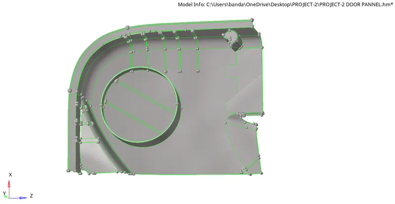
So I started making mid-surface from this surface region.
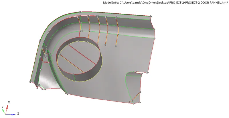
So it is a plastic component I started to do manual mid-surfacing.
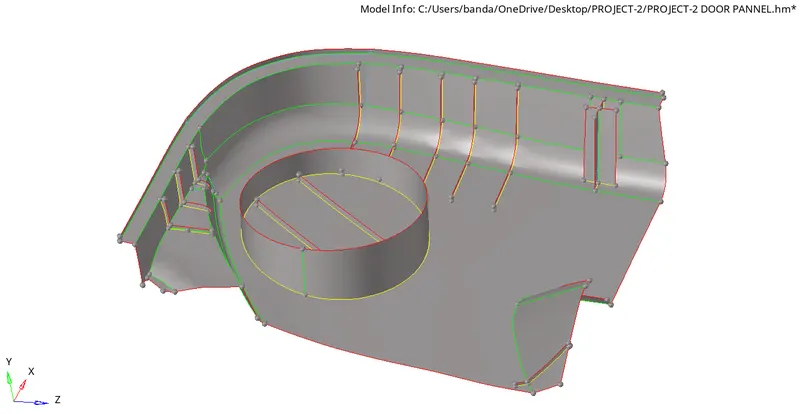
So I completed the region and corrected all the surfaces by checking all surfaces got attached properly in their position.
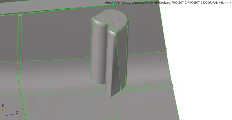
See here as they mentioned before in the project guidelines to do if you found these structures you have to work out to form the mid-surface in this way.
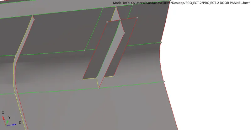
As they mentioned I created these types of surfaces instead of taking mid-surface for those structures.
Step 6:-
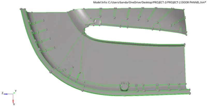
As I completed the part one region which is considered before now I choose to work on this surface to make mid-surface.
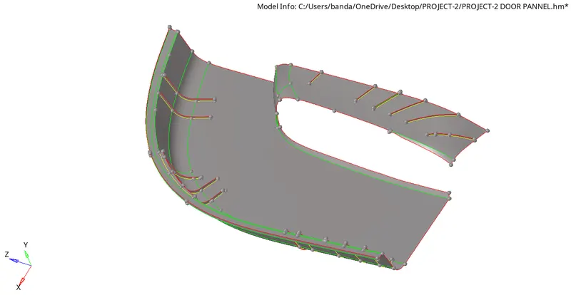
By correcting all the surface errors in forming the mid-surface I worked on here to attach the surface in contact between the surfaces as in the parent geometry.
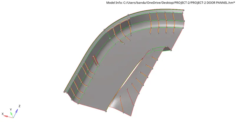
I completed this part 2 region also pretty well.
Step 7:-
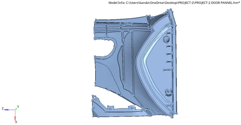
Now I started work on part 3 region.
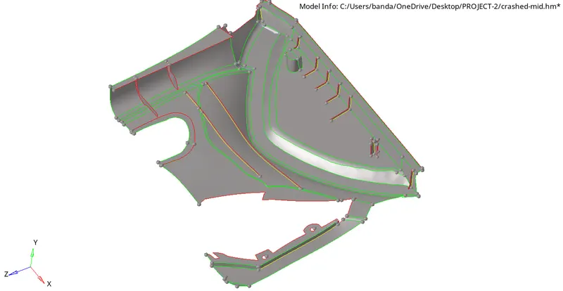
I cleared the errors like surface contact missing and some feature lines forming improperly and resolved all issues and formed the mid-surface properly.
Step 8:-
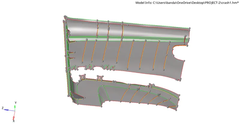
Finally, I reached to work on forming the mid-surface to the final region.
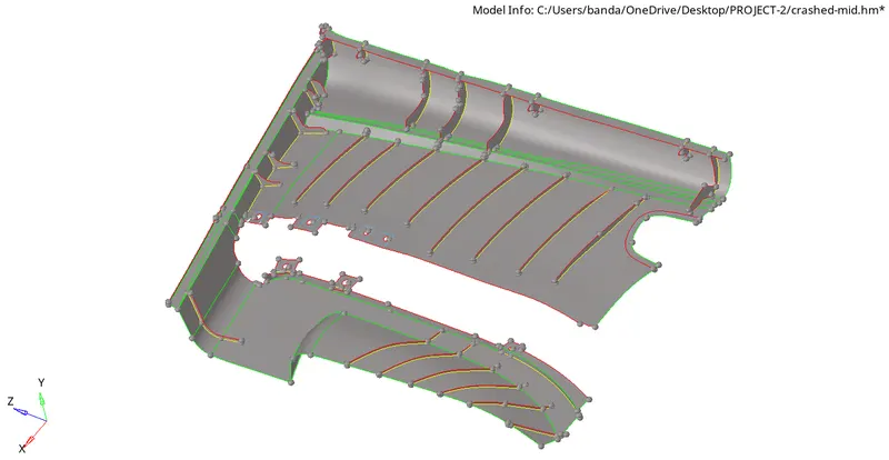
Here too I correct all the geometrical errors and carefully cleared all issued and checked twice to confirm it.
Step 9:-
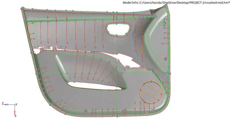
After forming the mid-surface individually I created a separate collector and I made all 4 mid-surface into that collector to make one mid-surface region for the whole component.
I had toggled the free edges and made the 4 regions into one mid-surface region.
Step 10:-
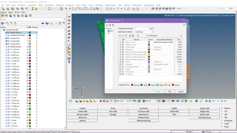
As given in the guidelines I had set the criteria file settings before meshing.
Step 11:-
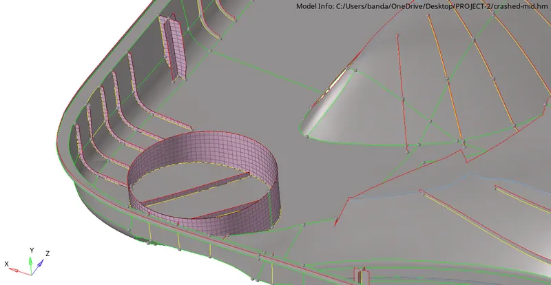
Now I started making meshing by following the given criteria.
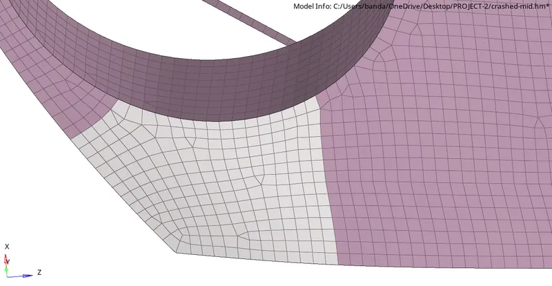
I gradually doing meshing the mid-surface region by region to get proper mesh flow.
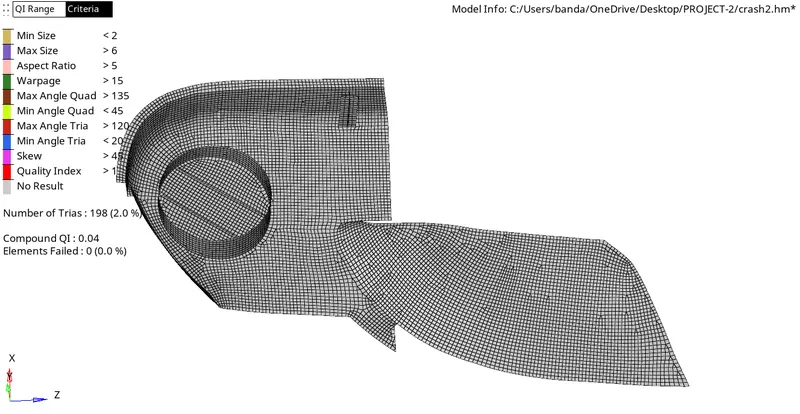
As you see I'm correcting the mesh flow and creating the mesh properly one by one.
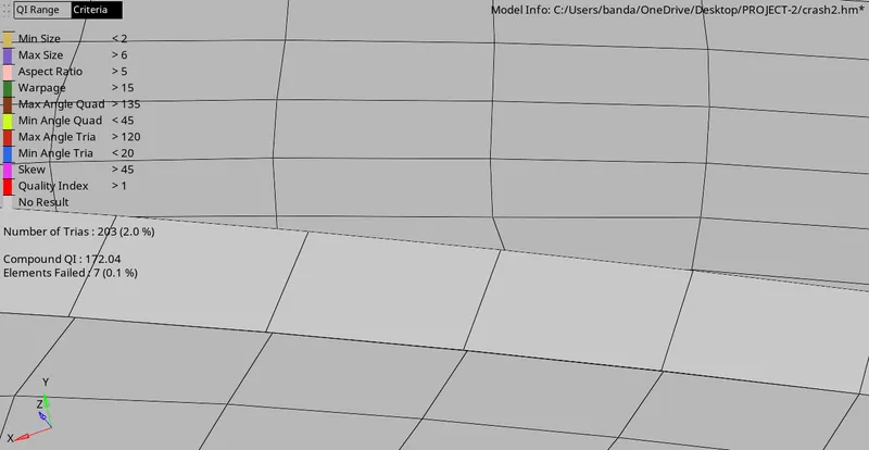
While doing meshing I observed some regions having no elemental connectivity.
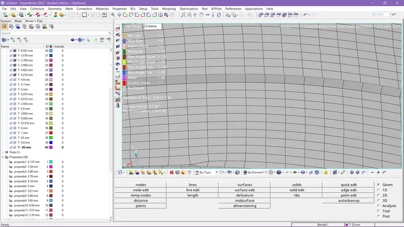
So I corrected this error using replace option.
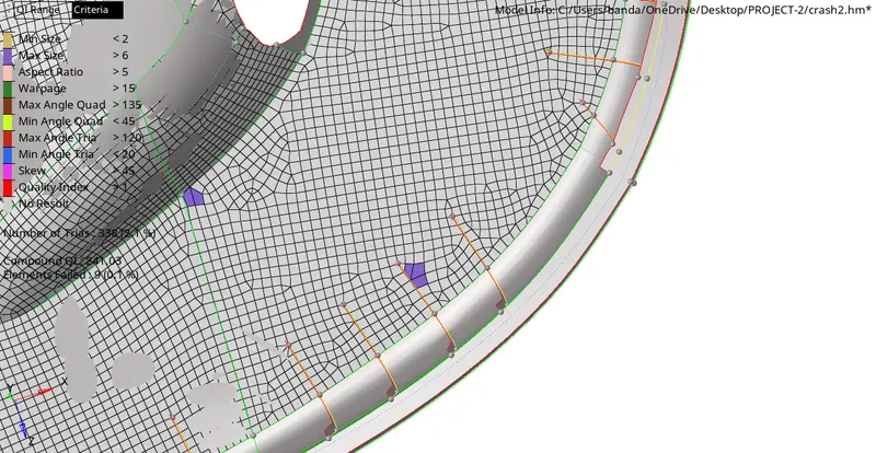
While performing meshing some of the elements got failed.
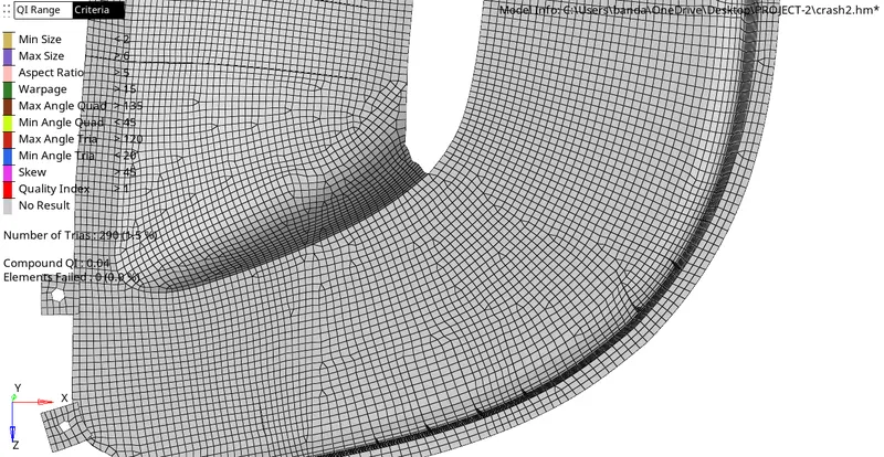
Here I rectified the errors and corrected the mesh flow.
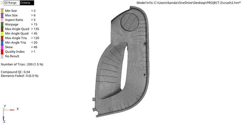
Gradually working on the mid-surface and solving the issues raised there.
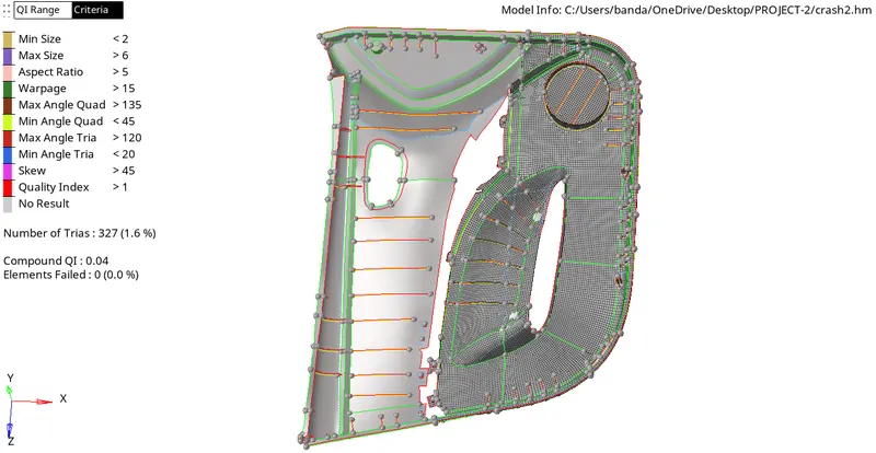
Half portion got completed in forming a proper mesh with mesh flow and here we also have to consider the amount of Tria's forming in the mesh, we can't totally avoid the Tria's but we can adjust and we can decrease them using the replace option by forming equal amount of elements forming mesh by considering rectangular regions so in this way we always have to search a way to work on this issue.
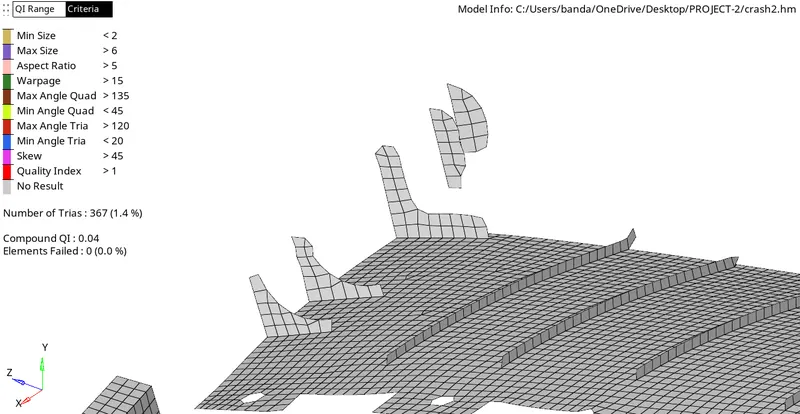
We need to take care of the mesh flow on the same side to follow the given criteria.
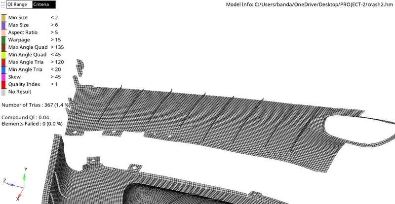
Have to be sure in confirming proper elemental connectivity in the mesh flow.
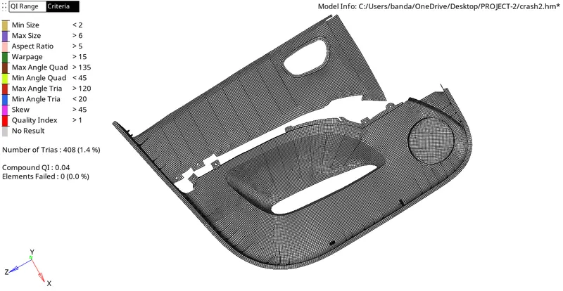
Carefully working on each and every region to form proper mesh flow.

The maximum region got formed mesh and we got some last regions to be need to work on.
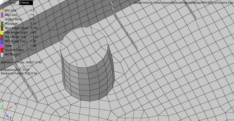
Forming a mesh by correcting the mid-surface in this type of surface is important to capture the mid-surface as much as we can to resemble the parent component.
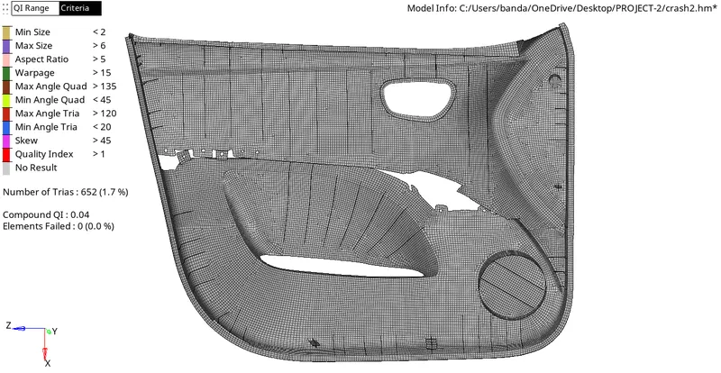
Finally completed forming a mesh on the mid-surface with proper mesh flow.
Step 12:-
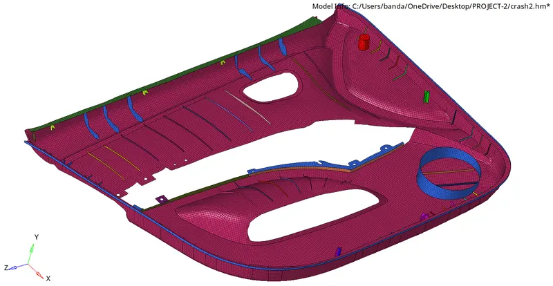
After meshing I created different collectors and created different properties by measuring the parent component thickness, I also assigned the thickness to the elements.
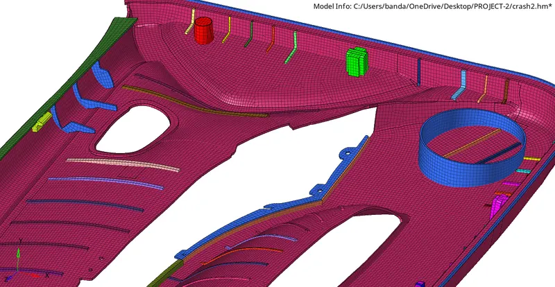
As you observe in the above picture the thickness is assigned individually to their respective surface.
Result:-
By completing all the corrections we completed the task according to the given criteria.
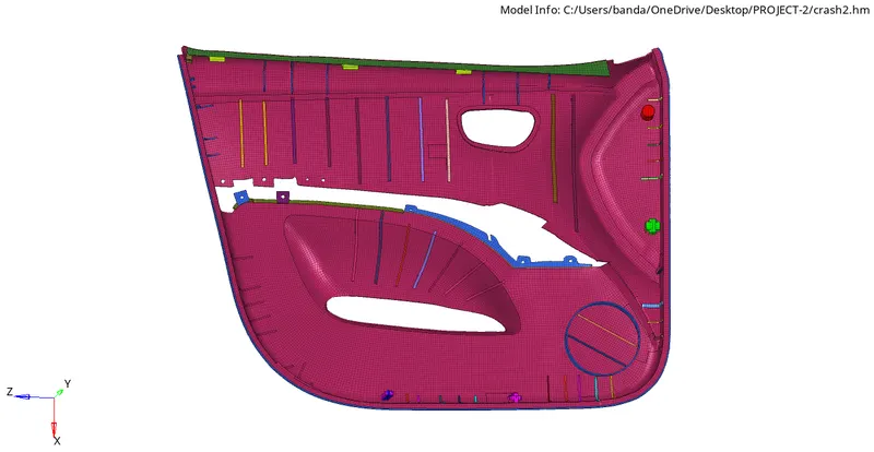
Below are the Quality criteria for the Plastic Model:
Target Element Length = 4 Units
| S.N | Quality Criteria | Value |
| 1 | Aspect Ratio | 5 |
| 2 | Skewness | 45 |
| 3 | Warping | 15 |
| 4 | Taper | 0.5 |
| 5 | Min. Length | 2 Units |
| 6 | Max. Length | 6 Units |
| 7 | Min angle Quad | 45 |
| 8 | Max angle Quad | 135 |
| 9 | Min angle Tria | 20 |
| 10 | Max angle Tria | 120 |
| 10 | Tria % | 10 |
This is the final model of the components of satisfying all the given criteria.