Project 2 - 2D meshing on the instrumental Panel
AIM:-
The below-mentioned quality criteria have to follow, also meshing the component with a target size of 1 unit, and assigning thickness at last:
|
S.No |
Quality Criteria |
Value |
|
1 |
Target/Average length |
4 |
|
2 |
Minimum Length |
2 |
|
3 |
Maximum Length |
6 |
|
4 |
Aspect |
3 |
|
5 |
Warpage |
15 |
|
6 |
Skewness |
45 |
|
7 |
Jacobian |
0.7 |
|
8 |
Minimum Quad Angle |
45 |
|
9 |
Maximum Quad Angle |
135 |
|
10 |
Minimum Tria Angle |
30 |
|
11 |
Maximum Tria Angle |
120 |
|
10 |
Tria Percentage |
15 |
Procedure To Accomplish The Given Task:-
Step1:-
We have to Download the model and import it into ANSA software.
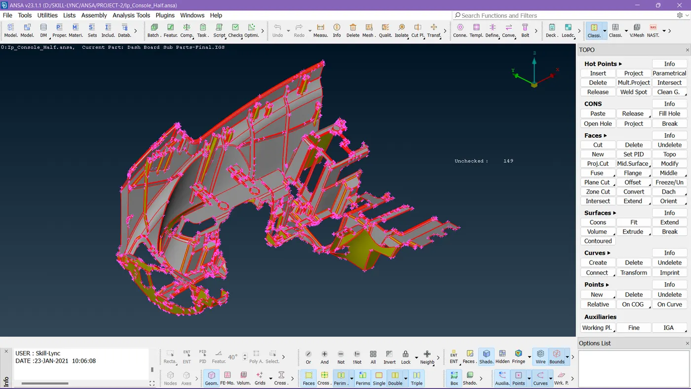
Step 2:-
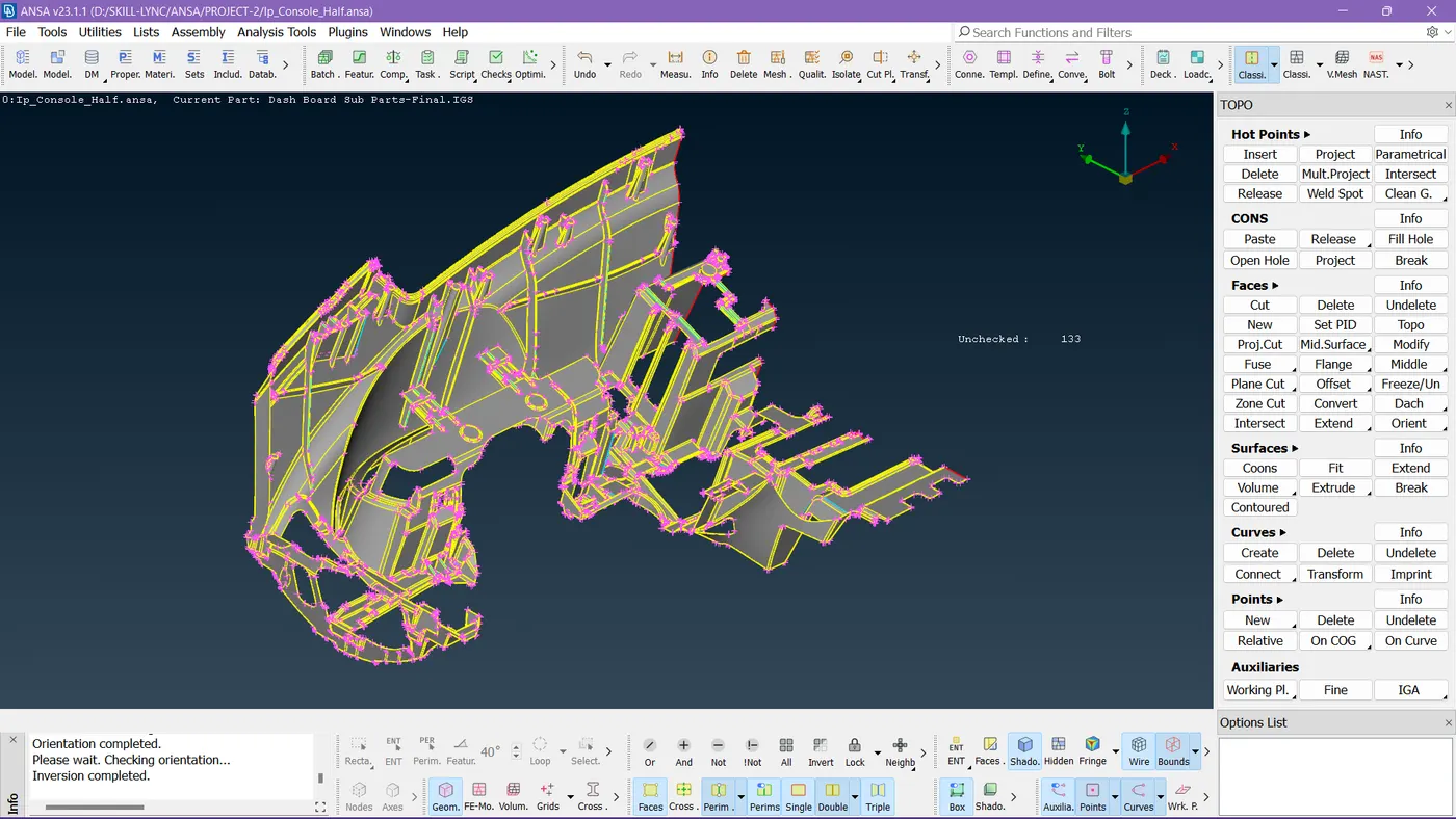
I did TOPO to the model to stitch the faces.
Step 3:-
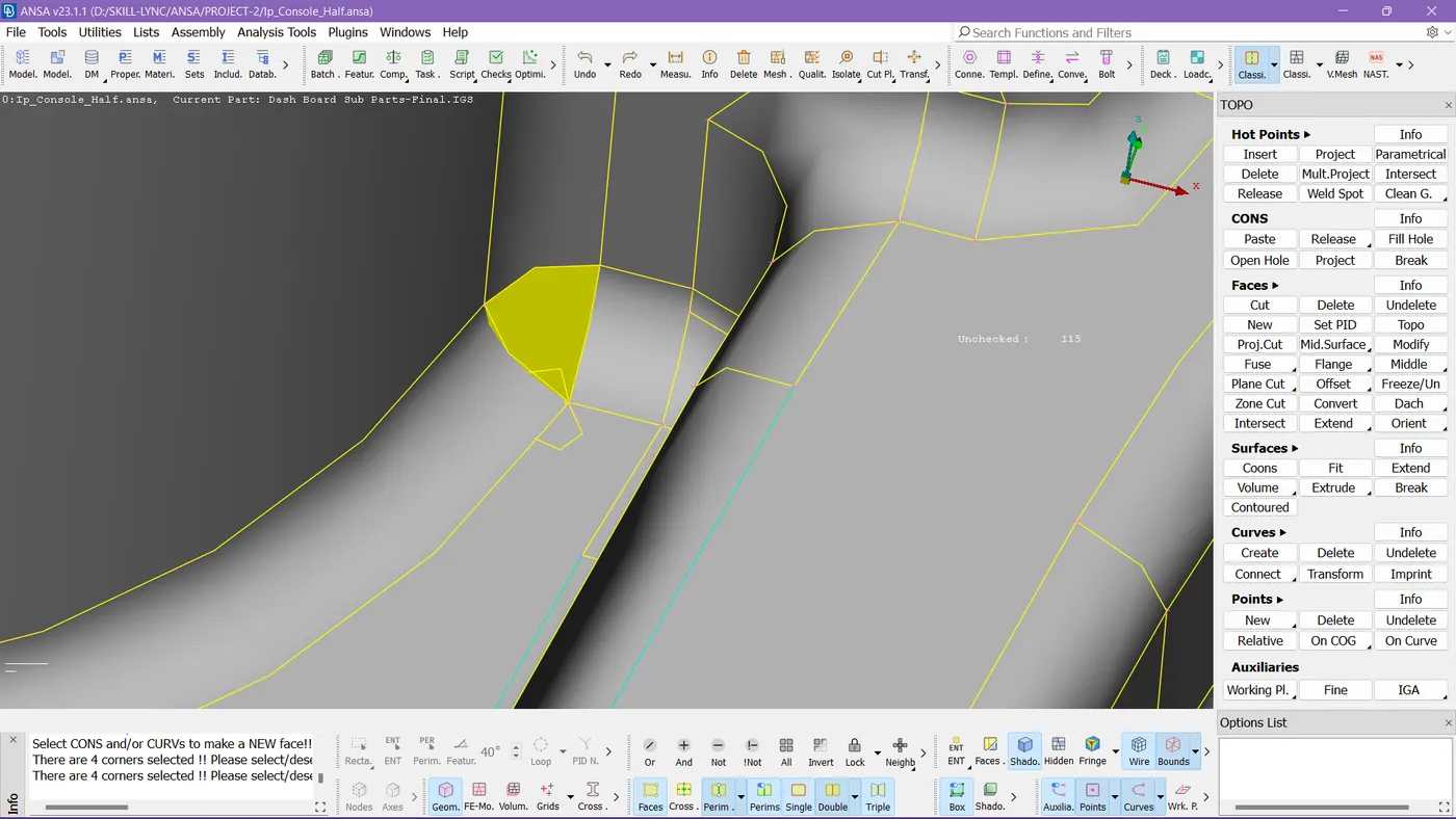
Here we can see the improper surface formation.
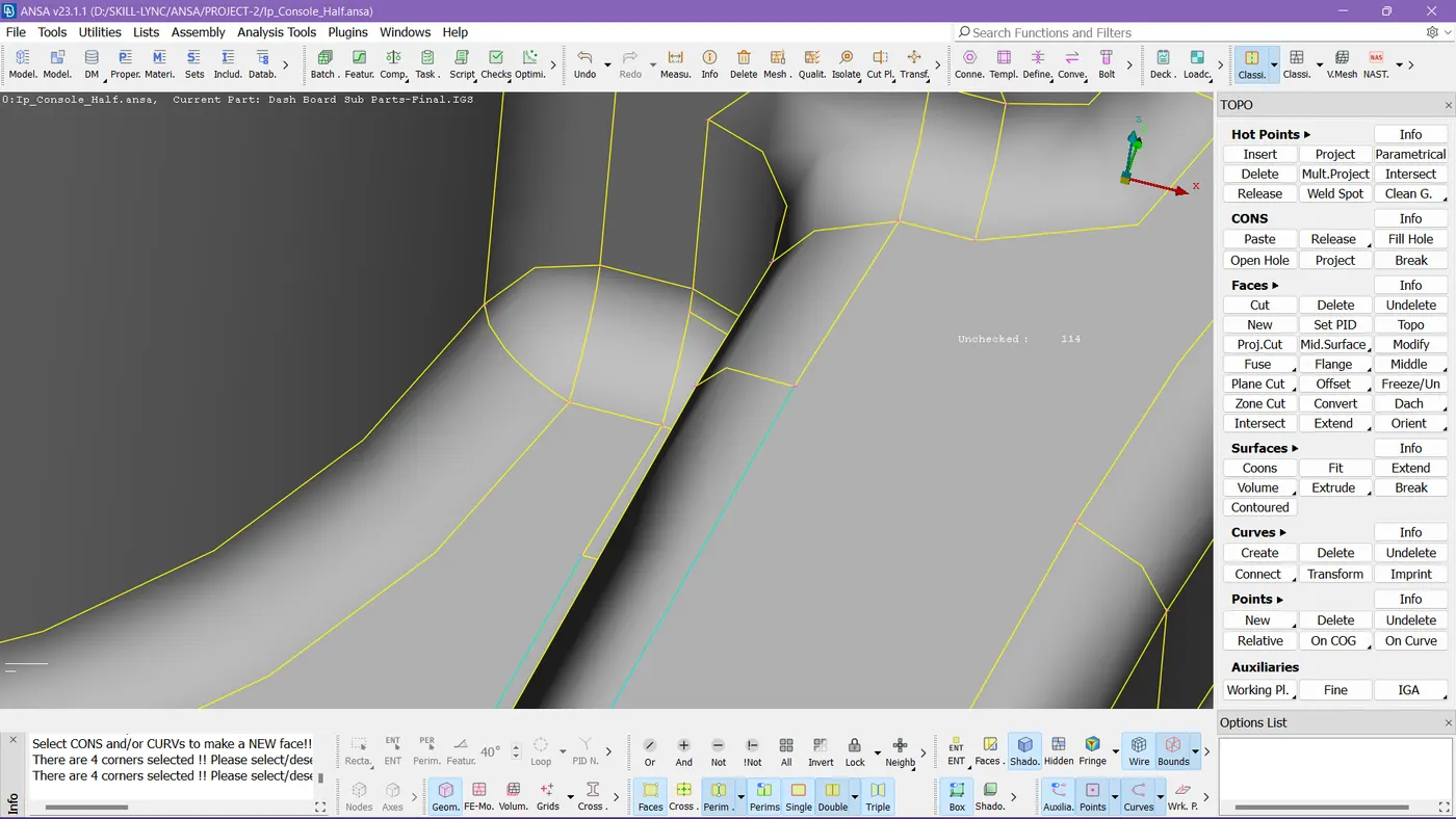
I deleted that improper surface and corrected it by building a new surface.
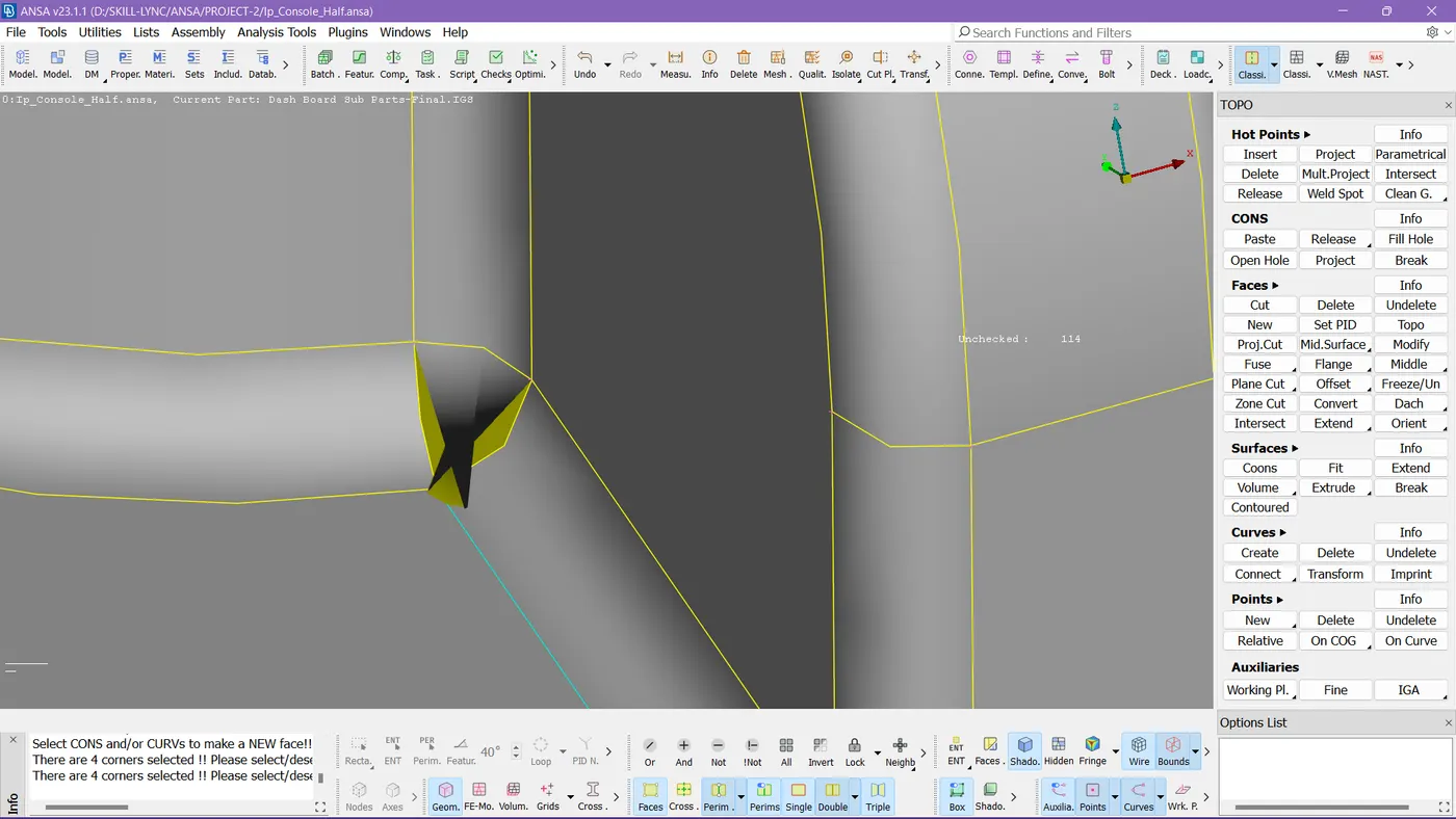
See here too some improper surface formation.
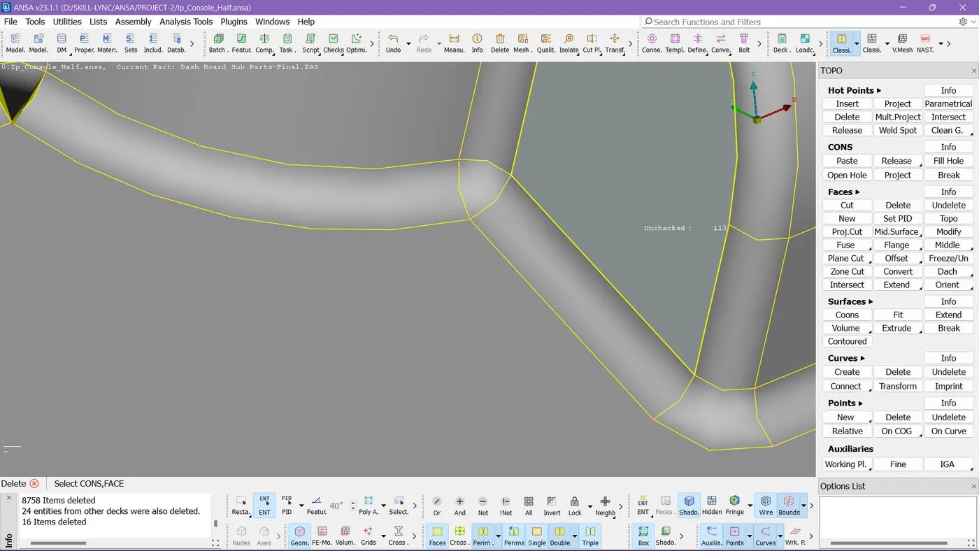
Deleting and forming new surfaces.
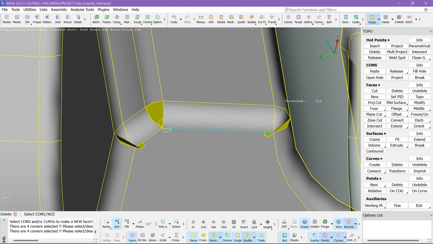
See how they are formed.
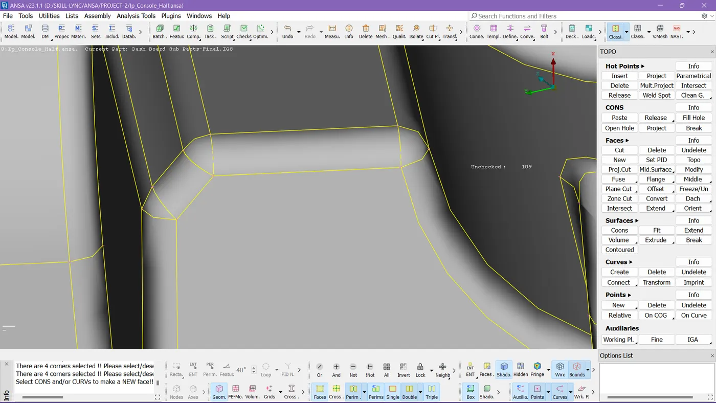
I'm correcting these types of surface issues as much as I can identify.
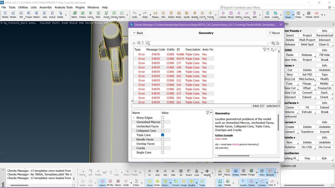
I did a geometry check after that to identify and confirm that there are no errors.
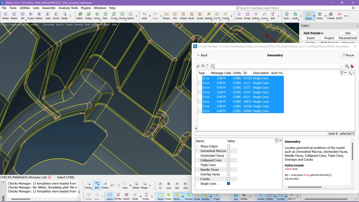
By doing auto fix I cleared some issues, and the remaining things iI solved them.
Step 4:-
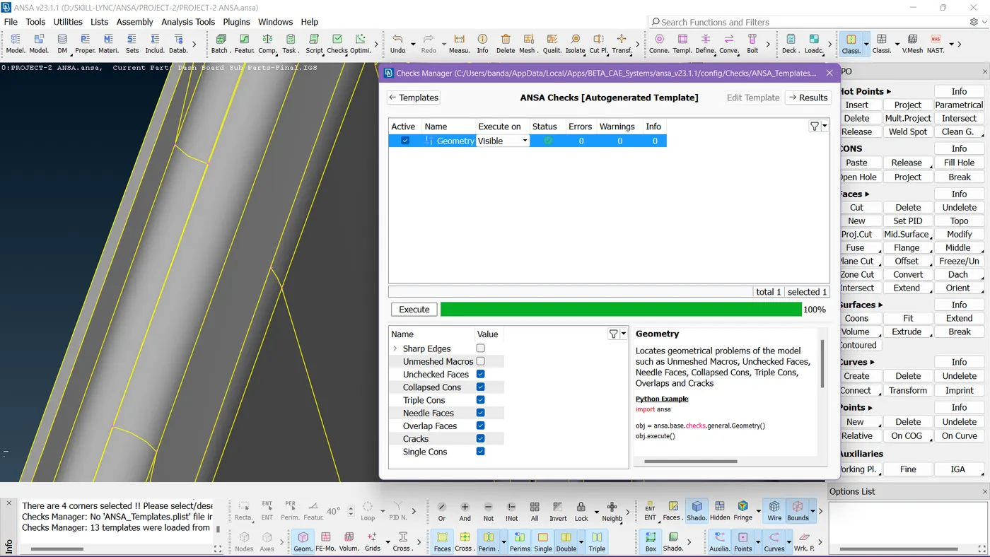
See I cleared all issues related to the given parent geometry.
Step 5:-
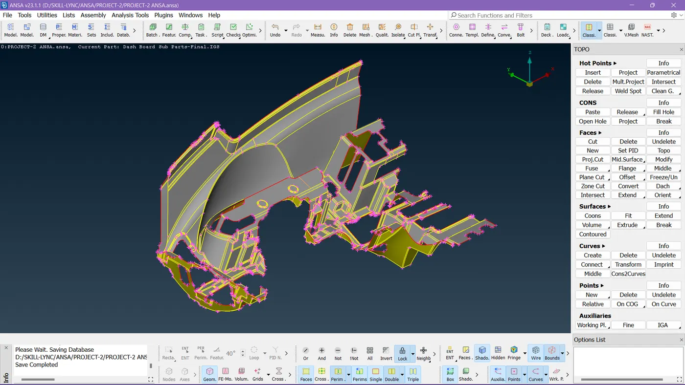
I started taking mid-surface manually and creating the PID at the same time.
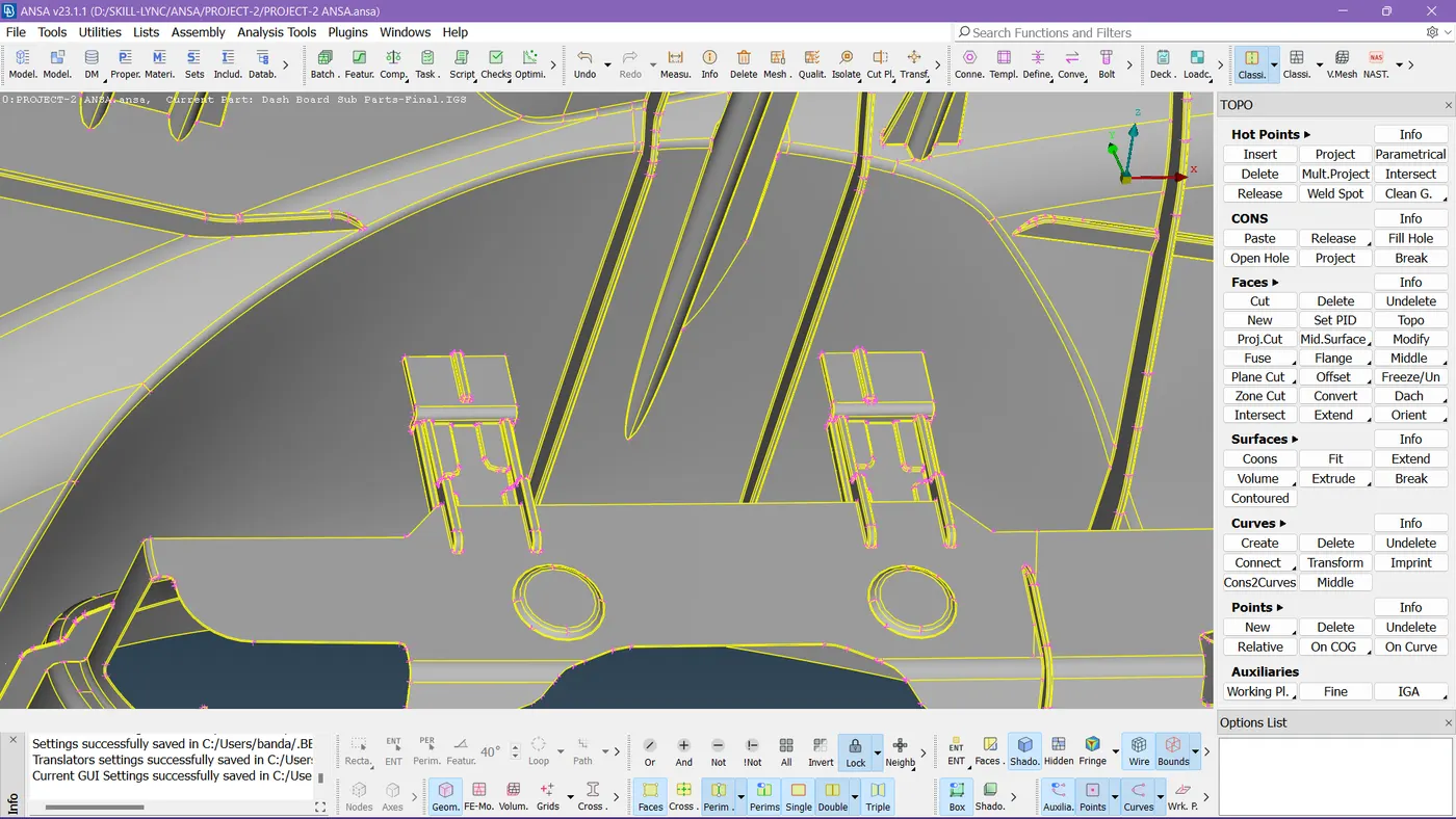
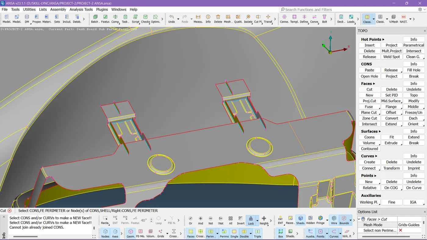
As in parent geometry, we need to capture every area by mid-surfacing.
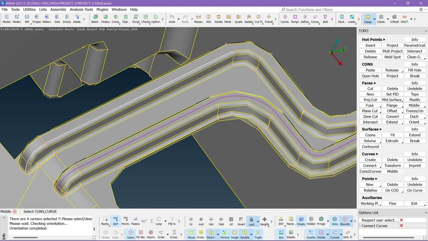
In some regions using the cons-curve option, we can form mid-surface.
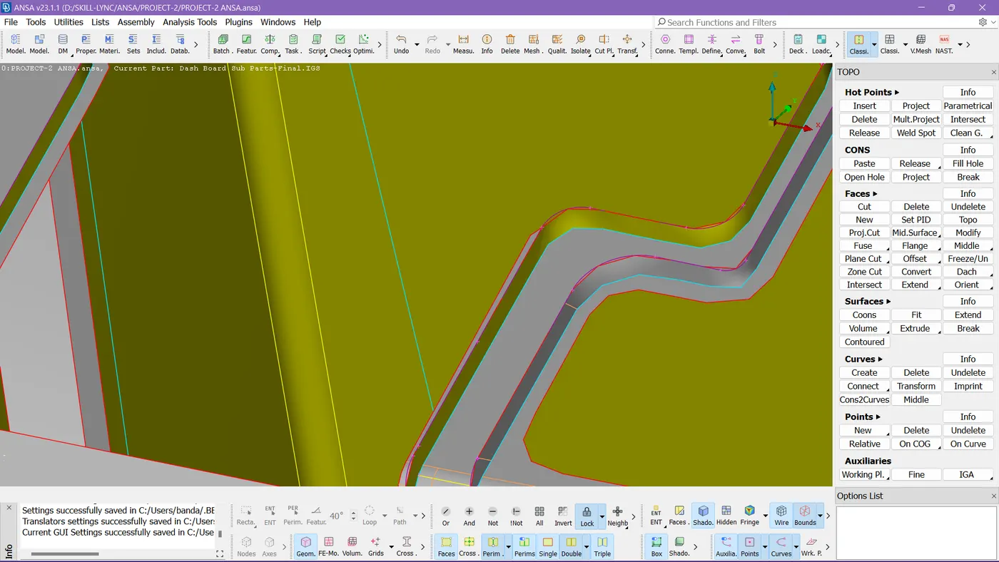
In this way, as we see in the image we can achieve to form mid-surface for those small ribs too.
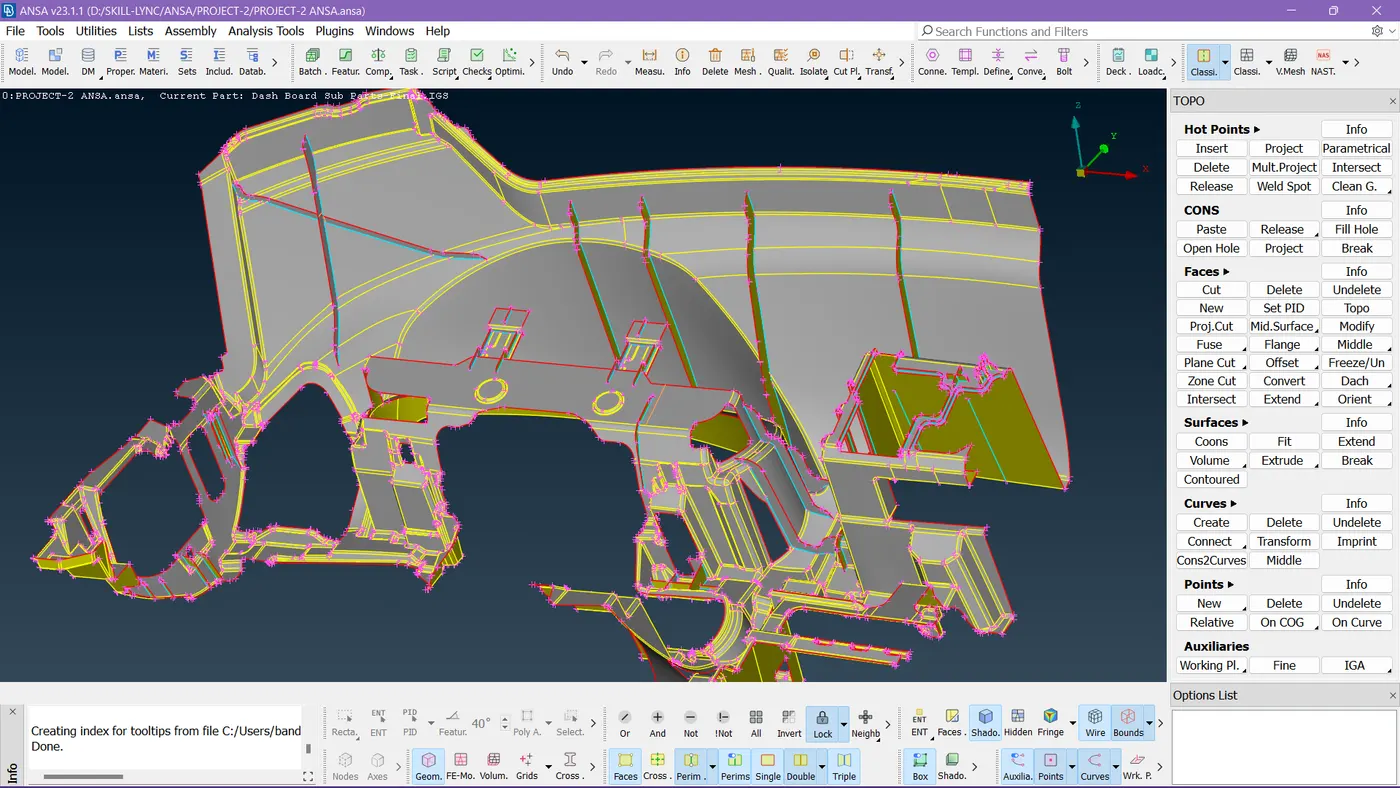
Upto now completed taking mid-surface to component but in the parent component, there are some solid elements also there to make mid-surface.
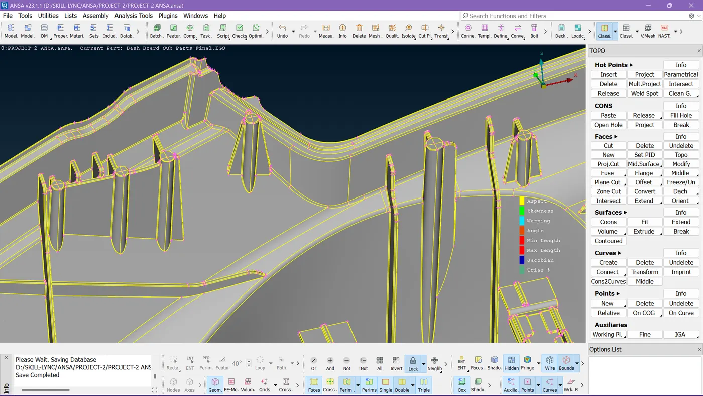
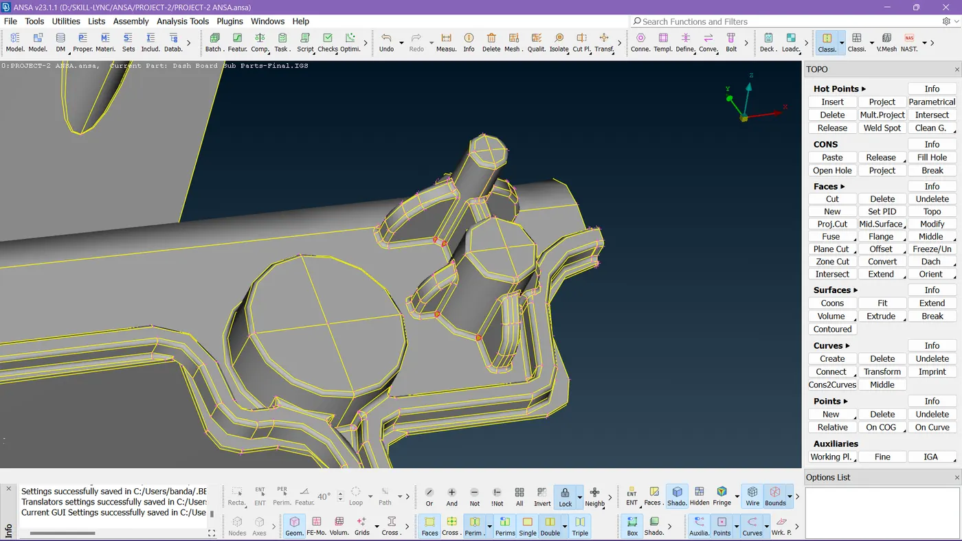
Here you can see the solid portions in parent geometry, we can't avoid them.
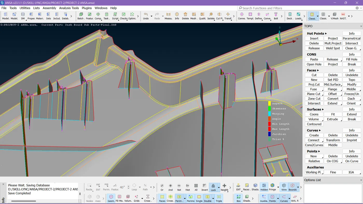
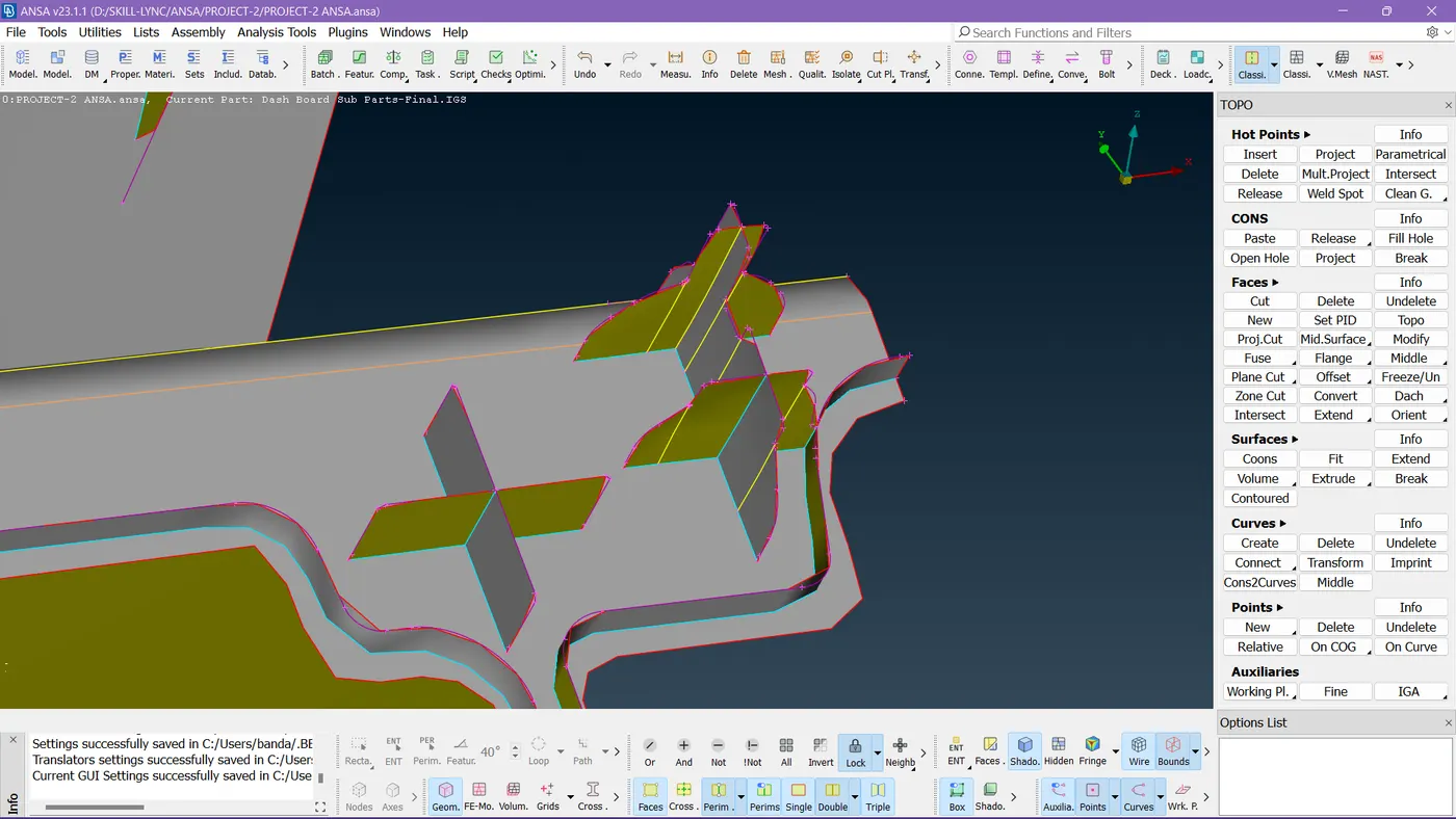
As shown in the above images I created the mid-surface and mentioned in the guidelines.
Step 6:-
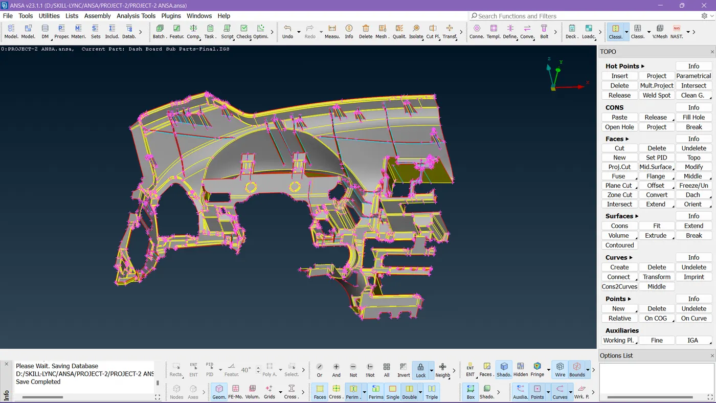
Totally completed taking mid-surface to the component.
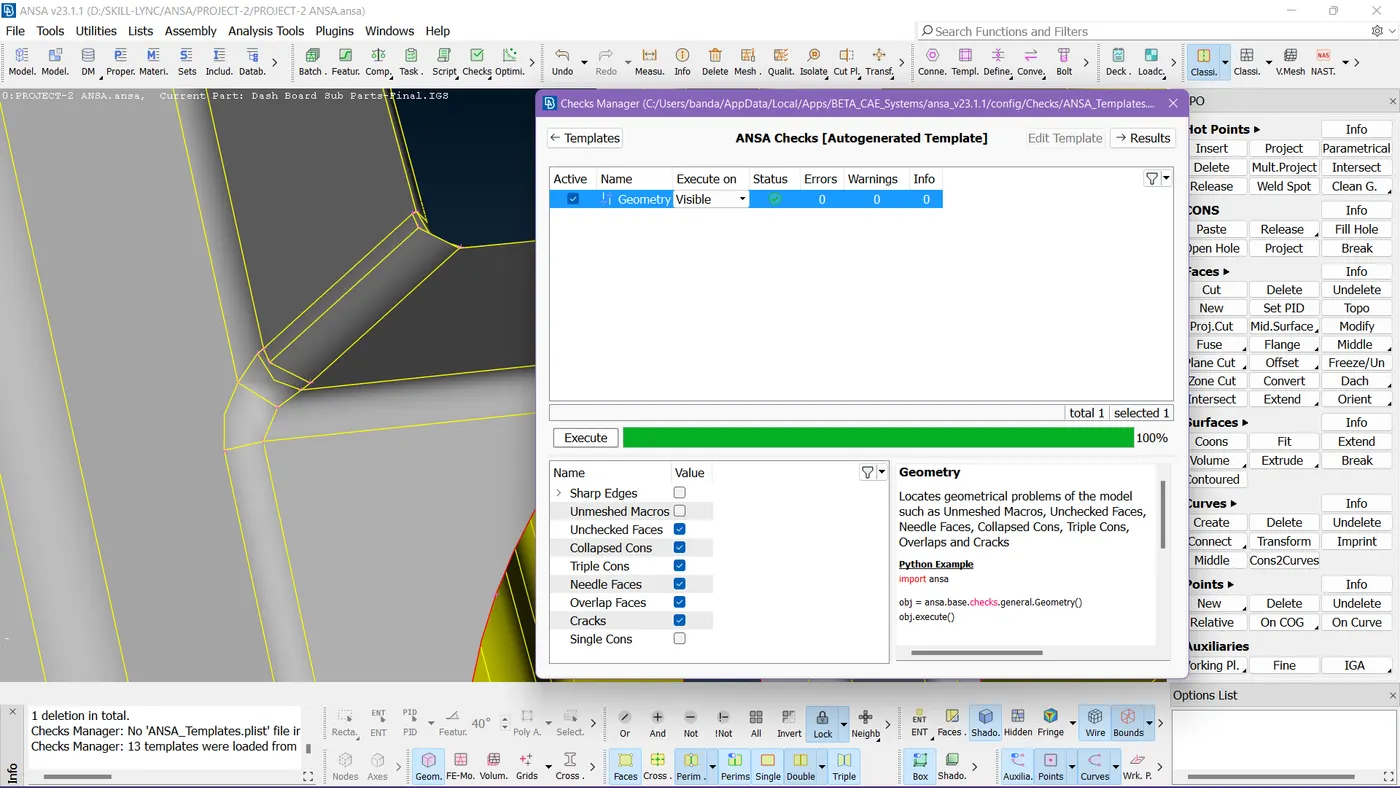
Also confirmed by running a geometry check on the mid-surface.
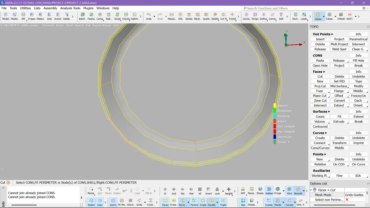
See here I noticed that the circular cons are very near so that there can be element failure confirmly.
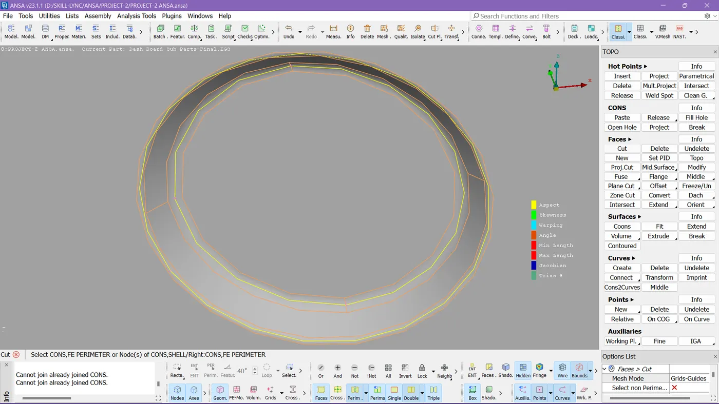
So created a mid-line and toggled the cons to solve this issue.
Step 7:-
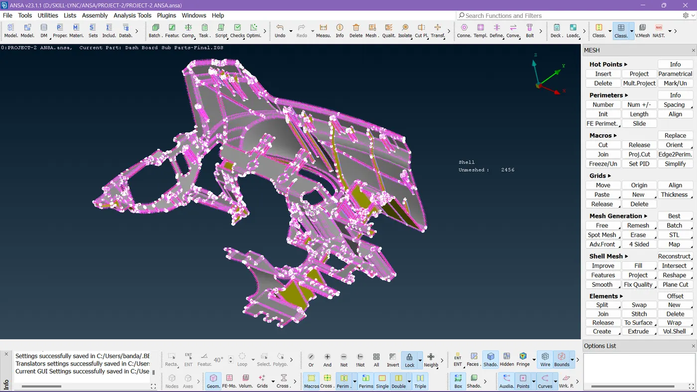
Now before mesh, I set down the given mesh parameters and quality criteria and we can see in the image I'm setting the target length of elements to the surface.
Step 8:-
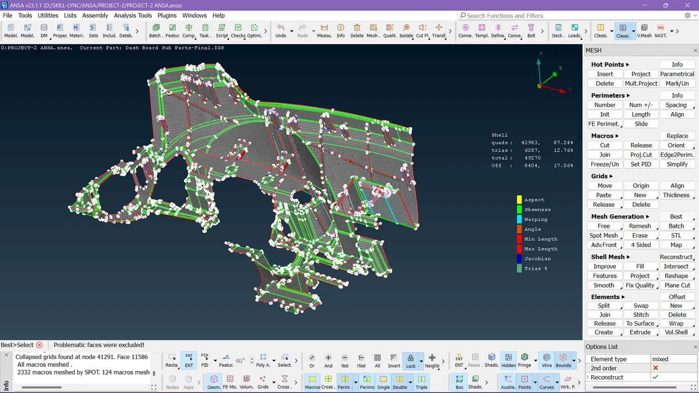
It is the initial mesh done on the surface, a lot of work needs to be done on this to correct all the issues.
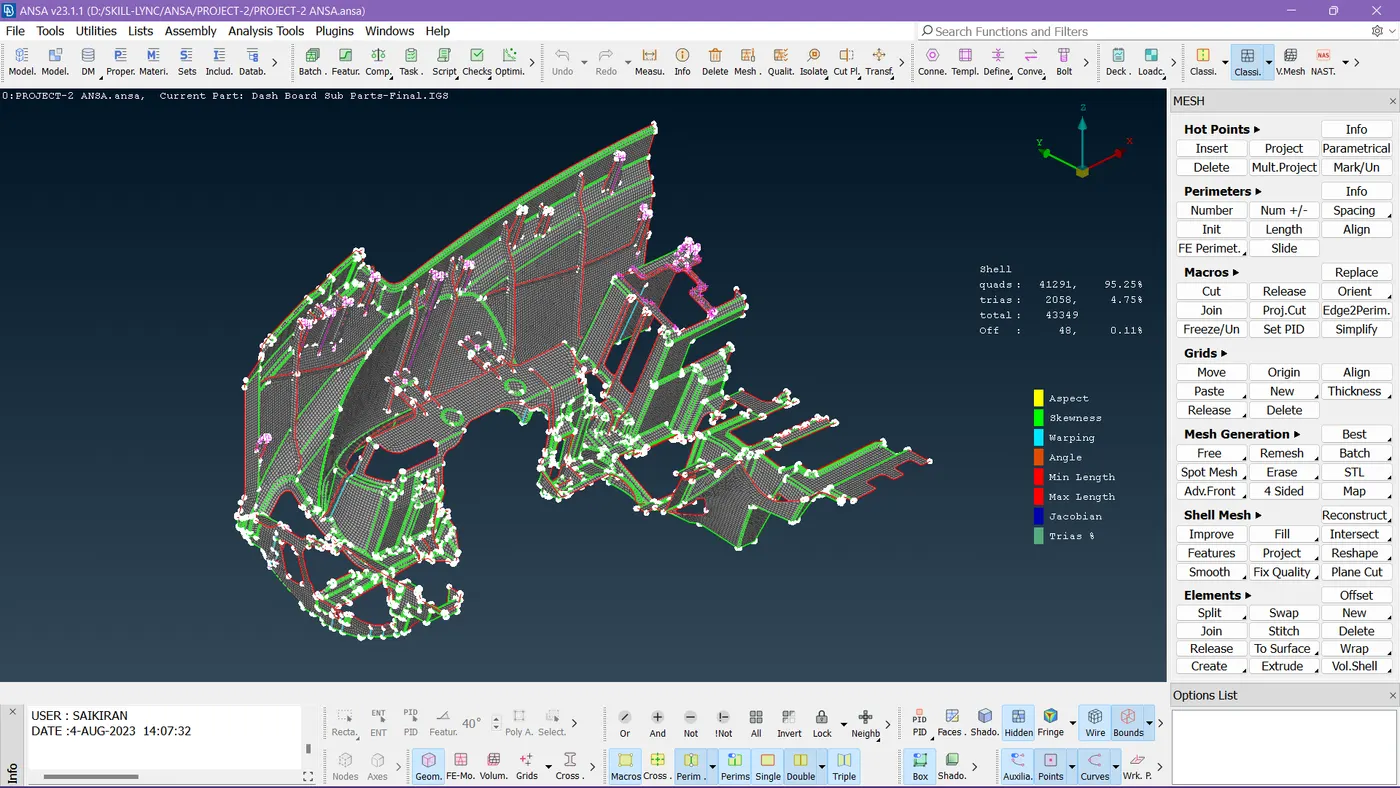
Finally, meshing was also completed.
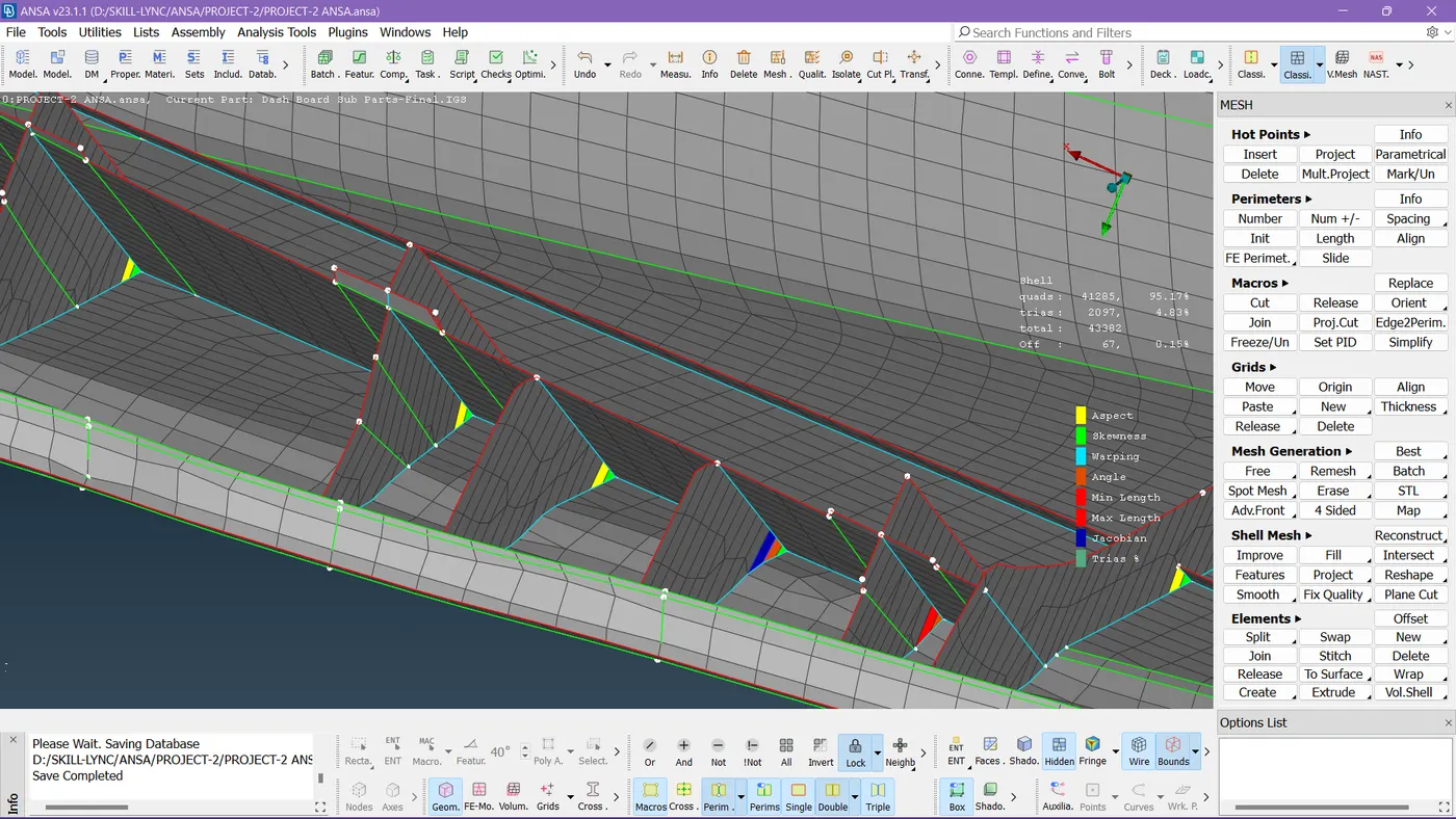
See here there are some failed elements, even though it is our responsibility to correct them I left them as they are because the main thing is capturing the surface area it is more important than the element's failure in very minute regions.
Step 9:-
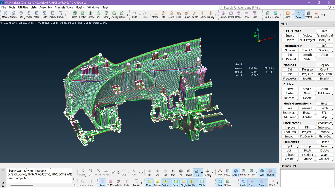
PIDs are also set down according to their thickness.
RESULT:
By completing all the corrections we completed the task according to the given criteria.
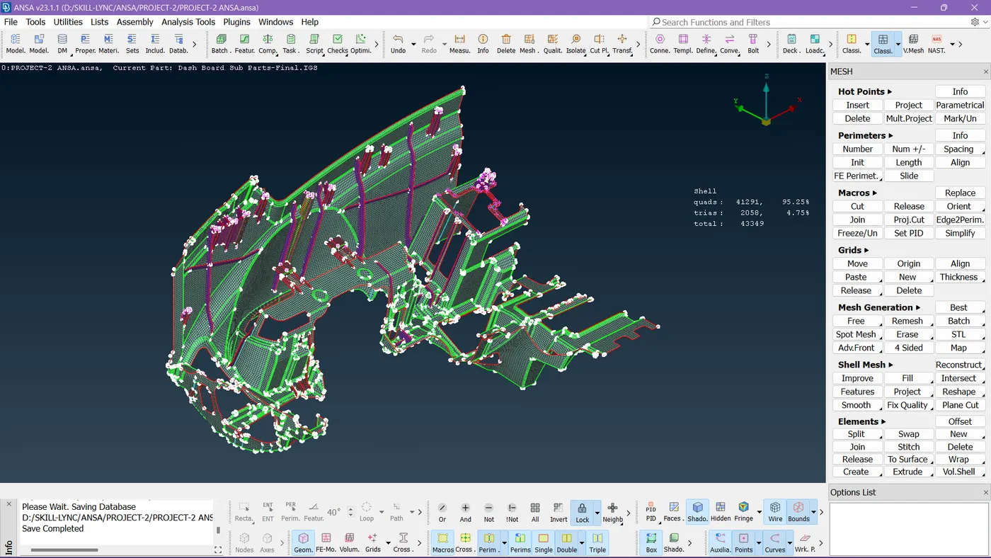
See here the shell elements are drawn to solid.
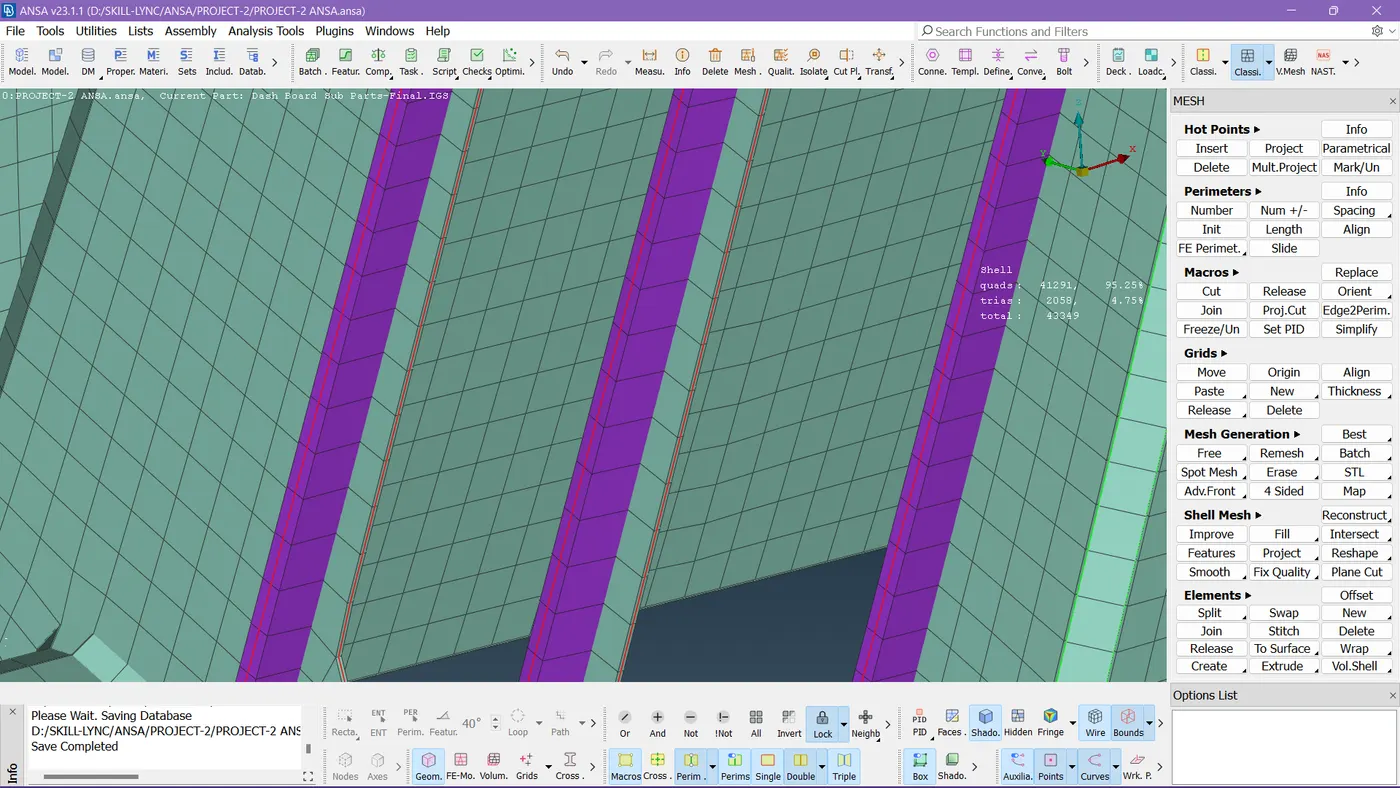
See here the thickness is visible which is set down according to the parent geometry.
--------------------------------------------------------------------------------------------------------------------------
Here the drive link of this project is been there: https://drive.google.com/drive/folders/1nQfNGUXdTe_PPXttXtMHglcHwG7TyQg3?usp=sharing