Assignment 5-RADIOSS Interfaces & Study of Effect of Notches Challenge
Q1).
OBJECTIVE: To create the esh for bumper assembly, the mesh size should be 6mm.
Step-1:
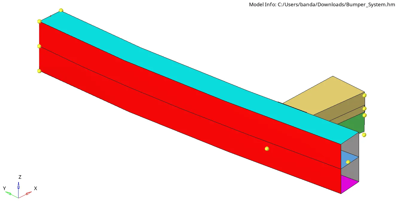
The given model was imported into Hypermesh.
Step-2:
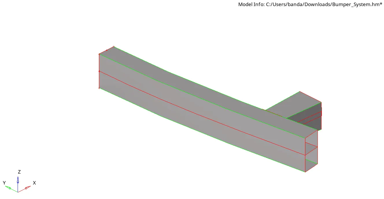
Checking the model's topology, some regions need to be addressed and made proper.
Step-3:
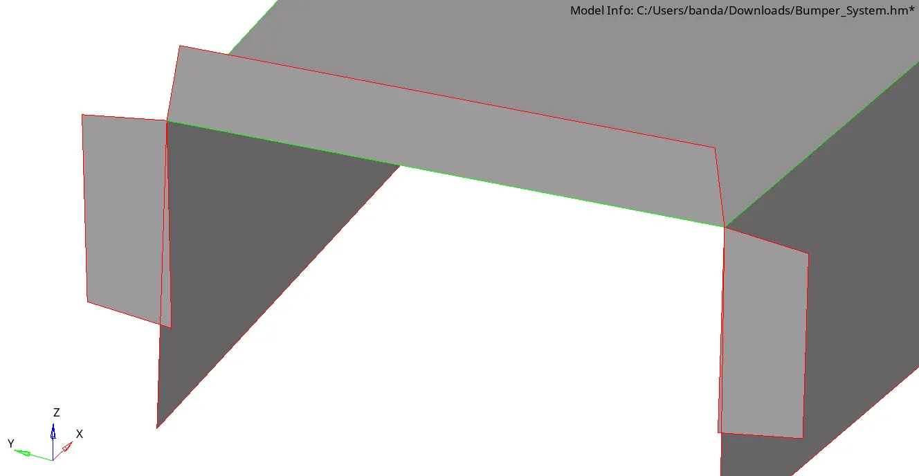
See here the surfaces are not connected properly they need to be corrected.
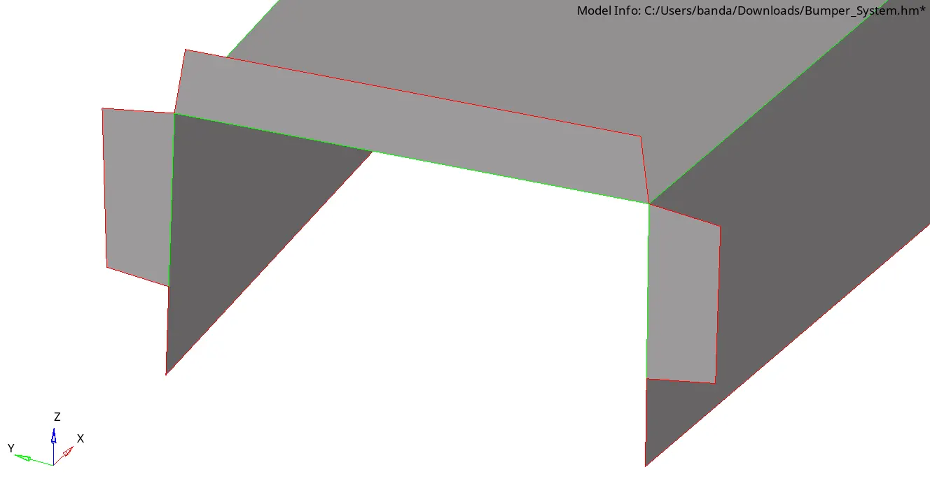
See how the surfaces are connected properly.
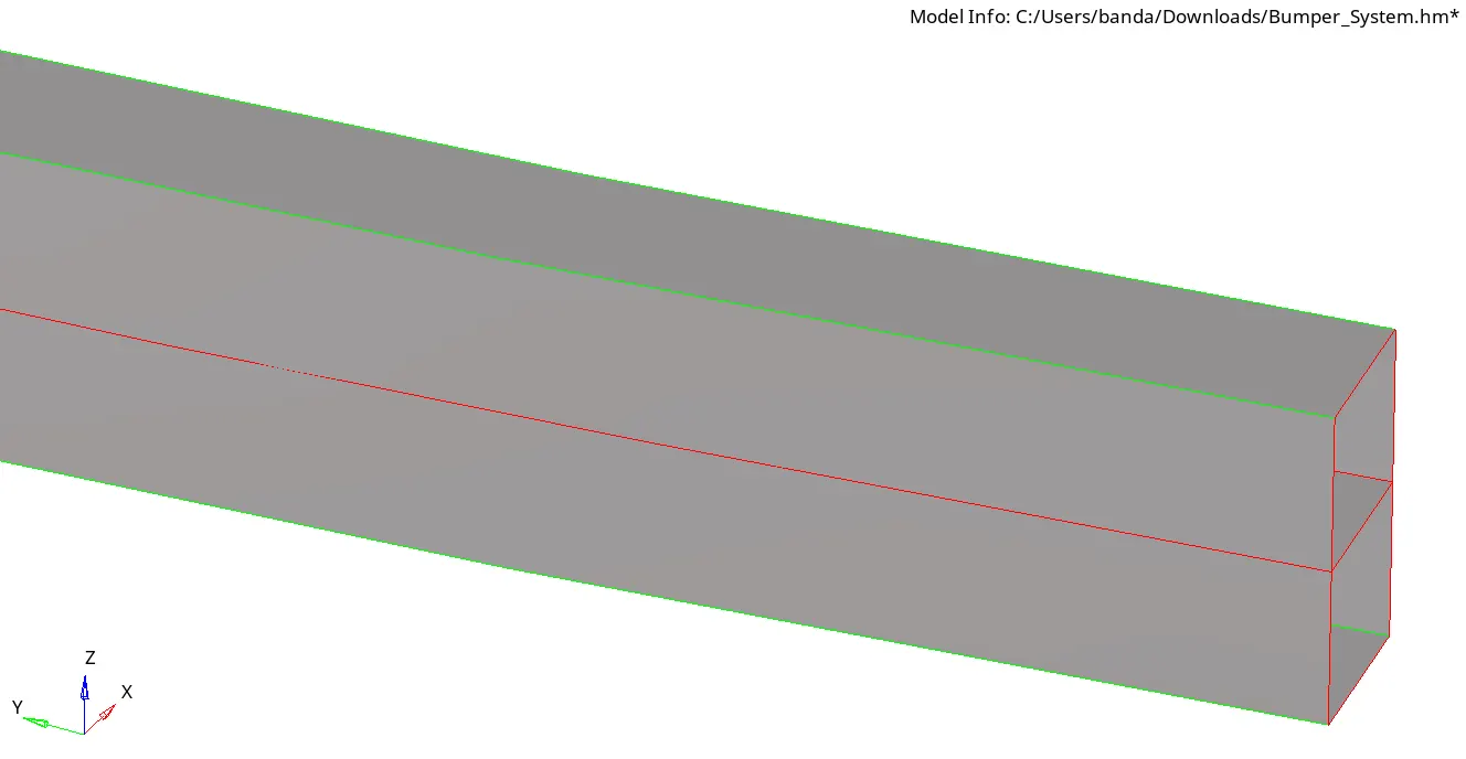
The middle surface is also troubling with free-edge which needs to be addressed.
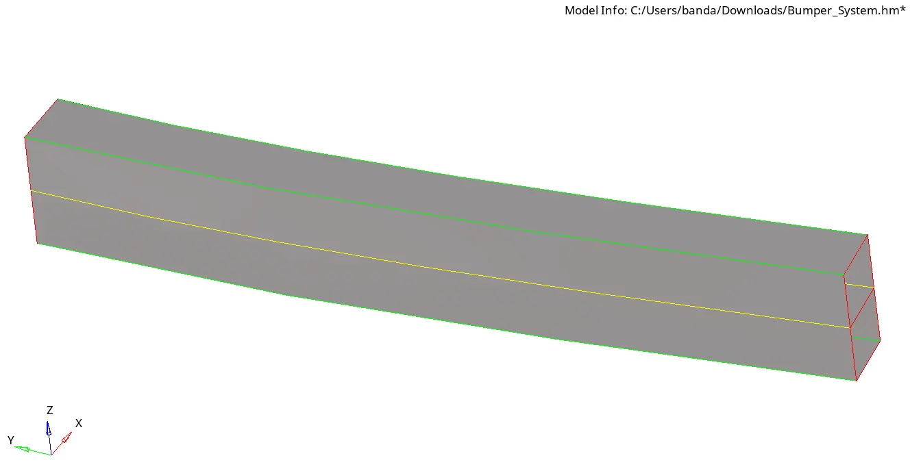
In this image, you can see the middle surface got connected as a T-joint.
Step-4:
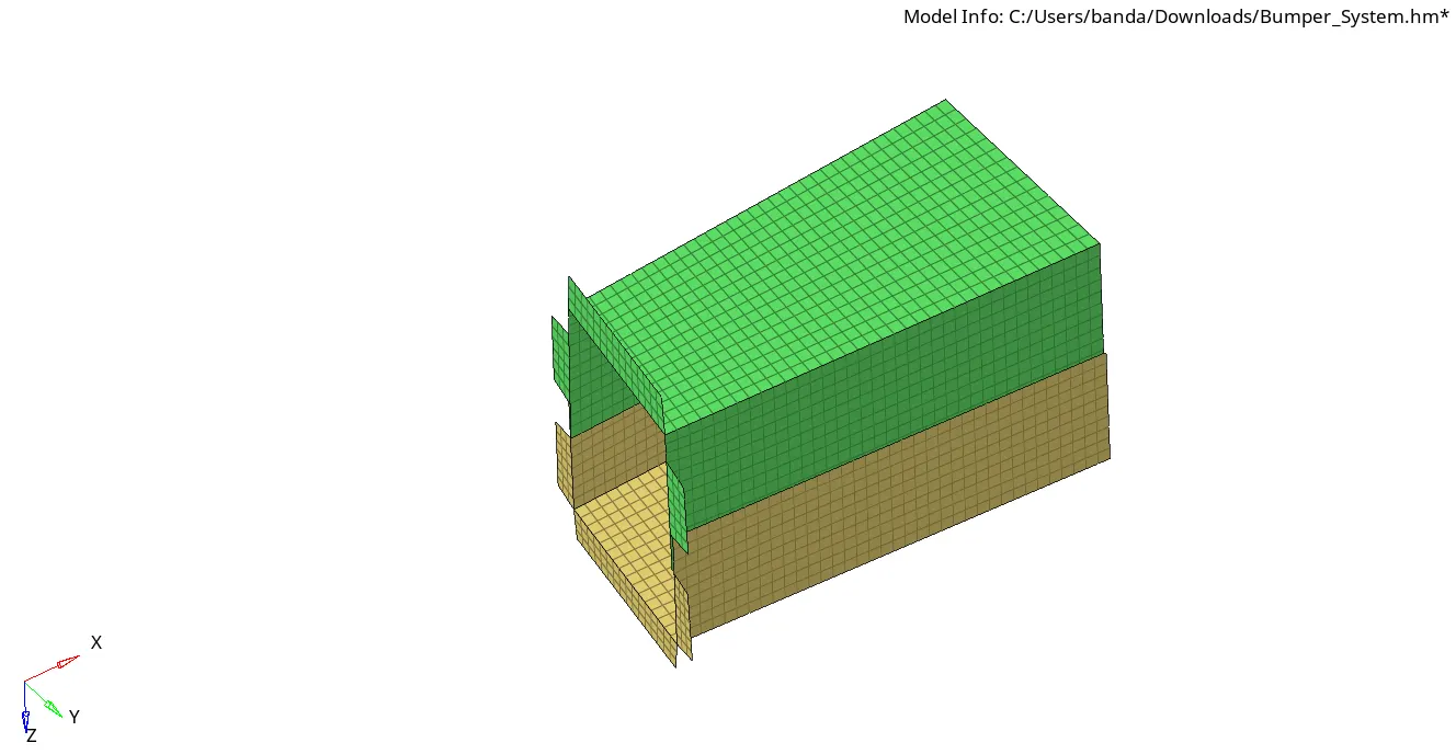
With the mentioned 6mm size I meshed the Crash_Box.
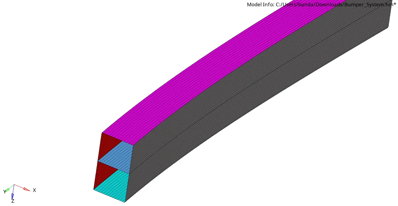
With the same 6 mm mesh size the Bumper_Beam also meshed.
Step-5:
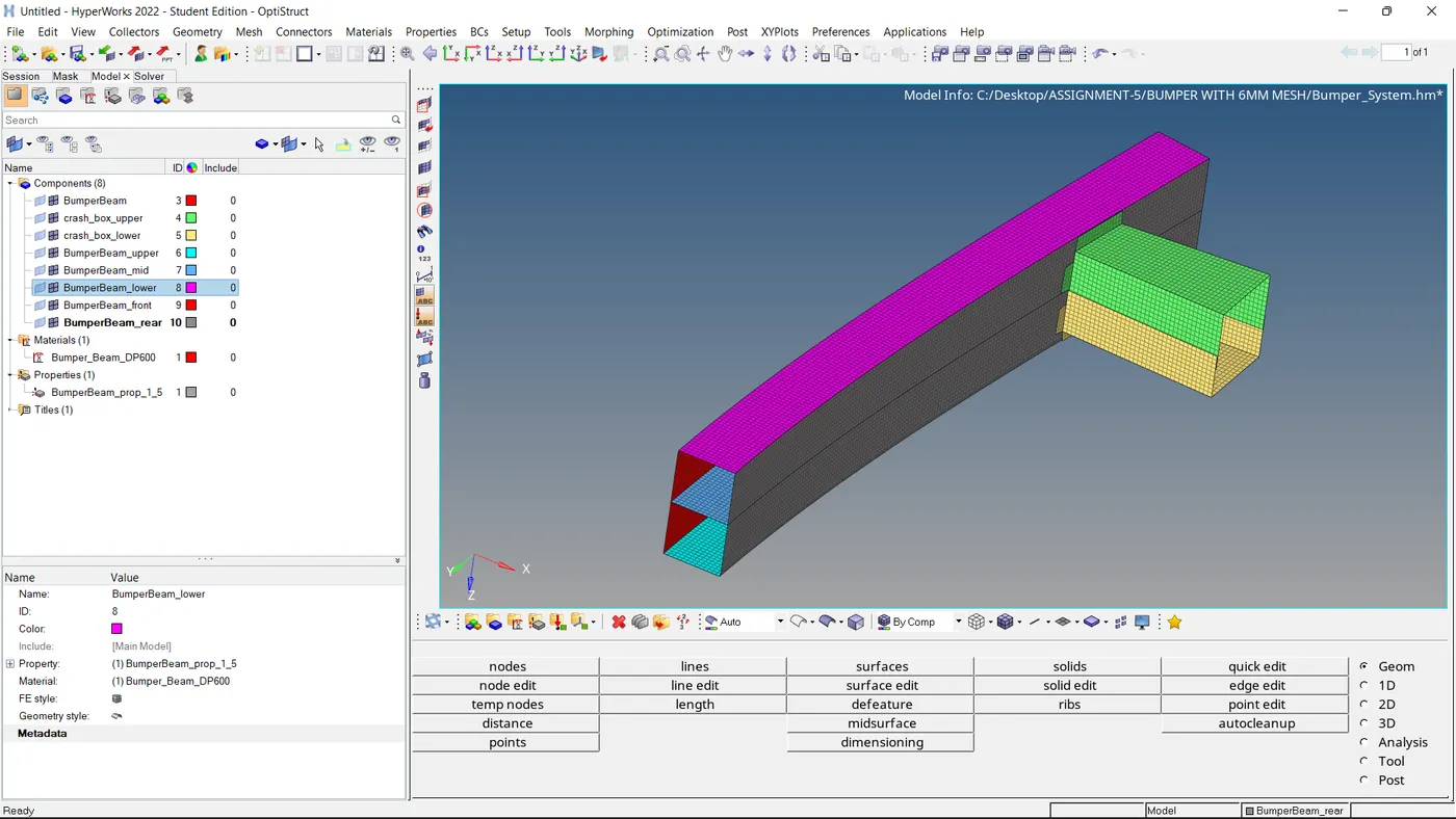
Finally, After meshing we need to assign the property and material to it.
-------------------------------------------------------------------------------------------------------------------------------------------------------
Q2).
OBJECTIVE: To know how the Notches affect the results and the impact of different types of contacts in each scenario.
Case-1: Run the crash tube model with the initial contact settings applied to it.
Step-1:
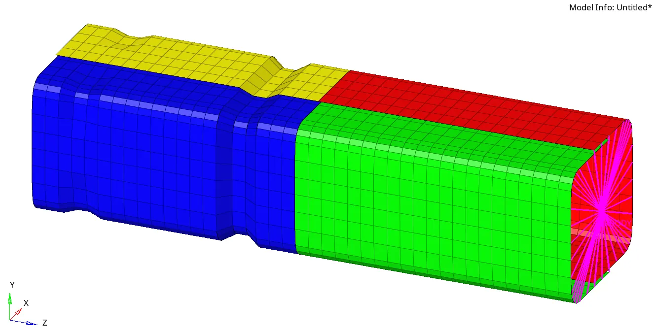
The model was imported into Radios.
Step-2:
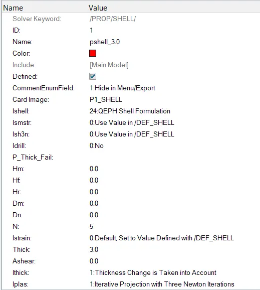
These are the Elemental Properties:
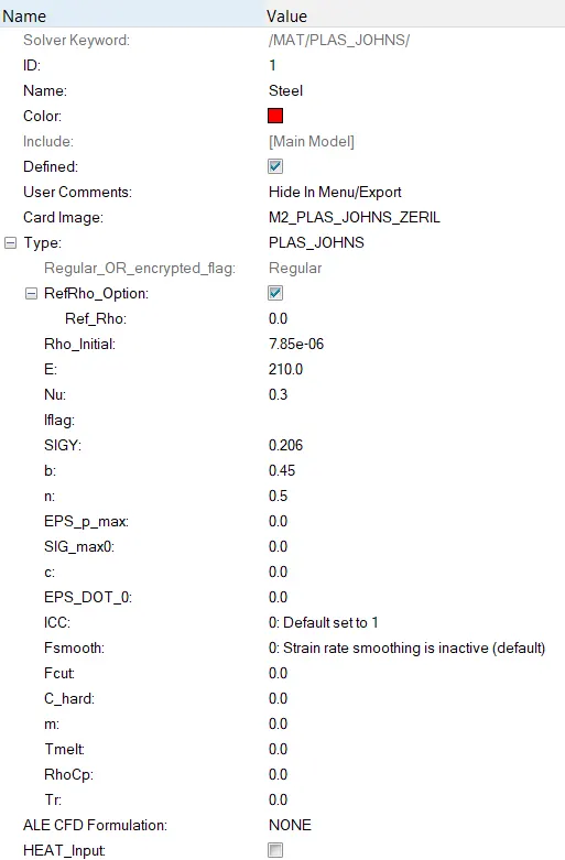
These are the material properties:
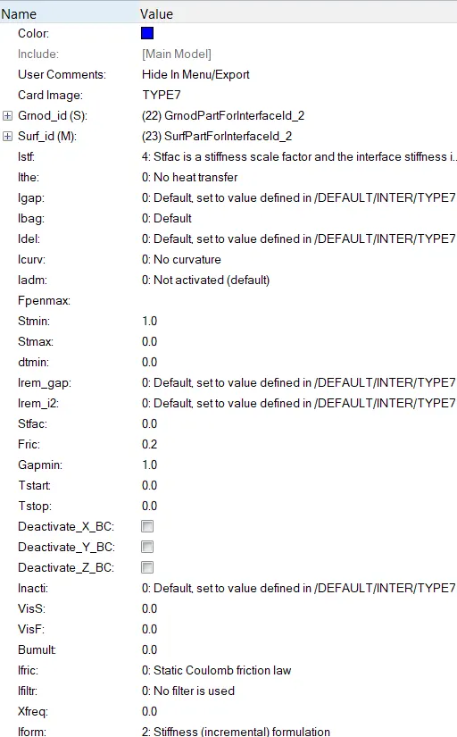
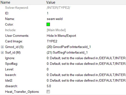
These are the Contact interfaces used:
Step-3:
Energy and mass errors are in the acceptable range so we are good to plot the results.
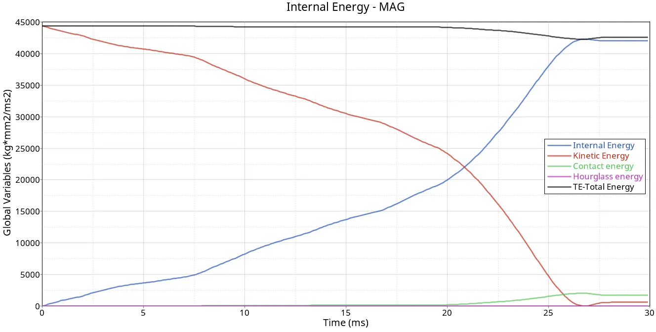
In the above energy graph, we can see the total kinetic energy is converted into internal energy, where the total energy is in a straight line around up to the 26th second while at that point there is an increase in contact energy which is reflected in Total energy.
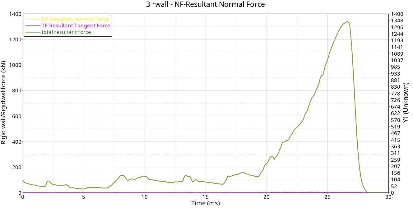
The total resultant normal force and total resultant force are all equal. At around 27 ms the component deformed fully and there is no chance to absorb energy by it.
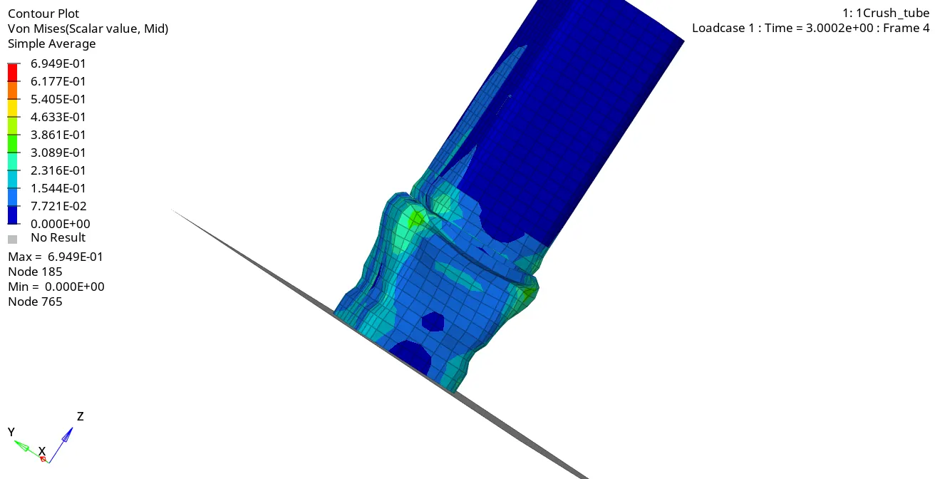
We can see the initial deformation taking place at the round notch area.
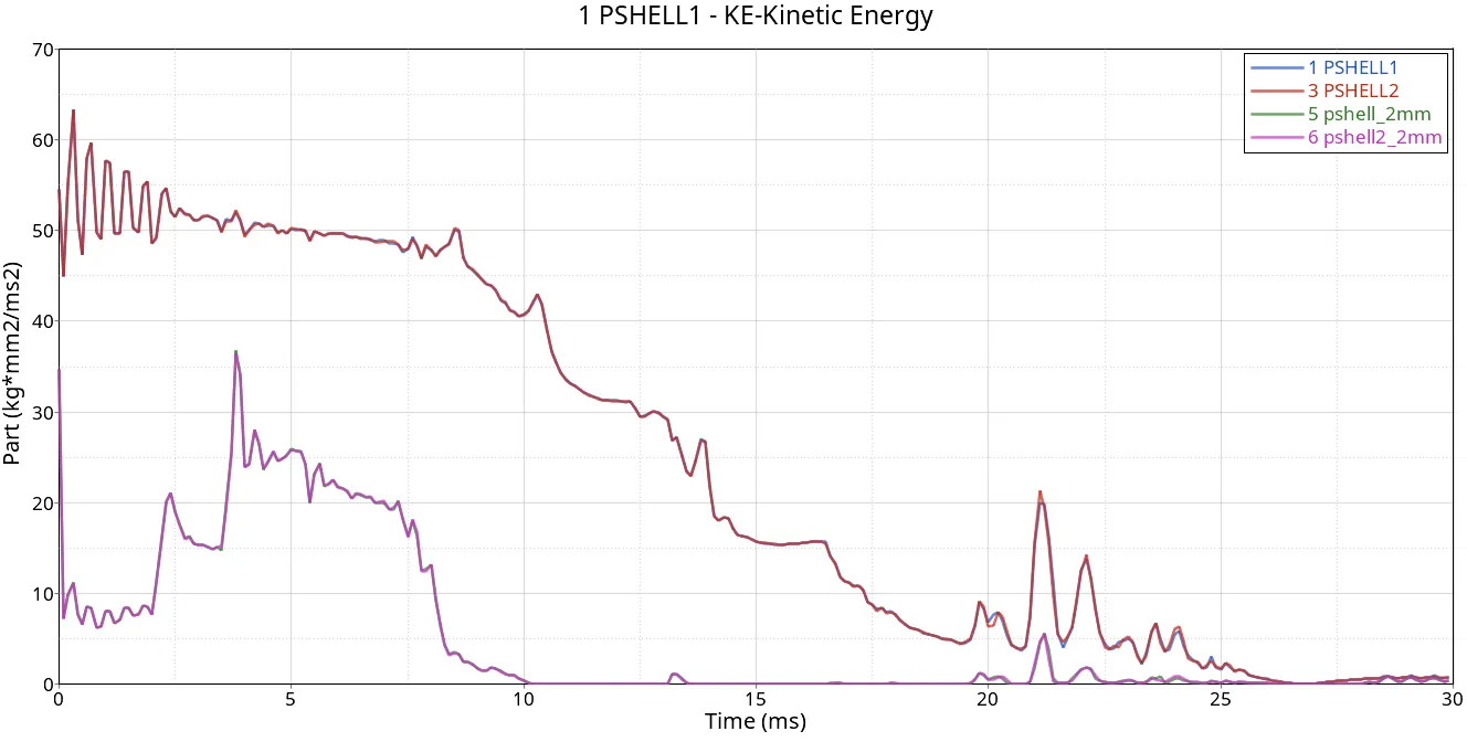
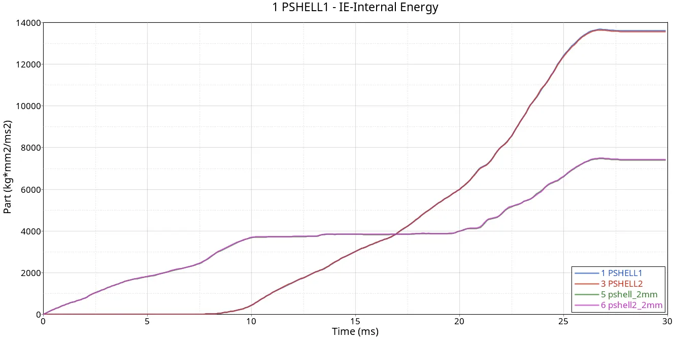
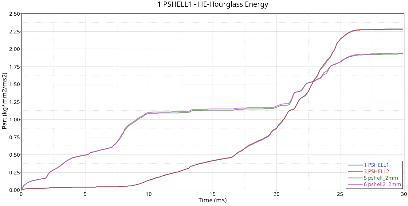
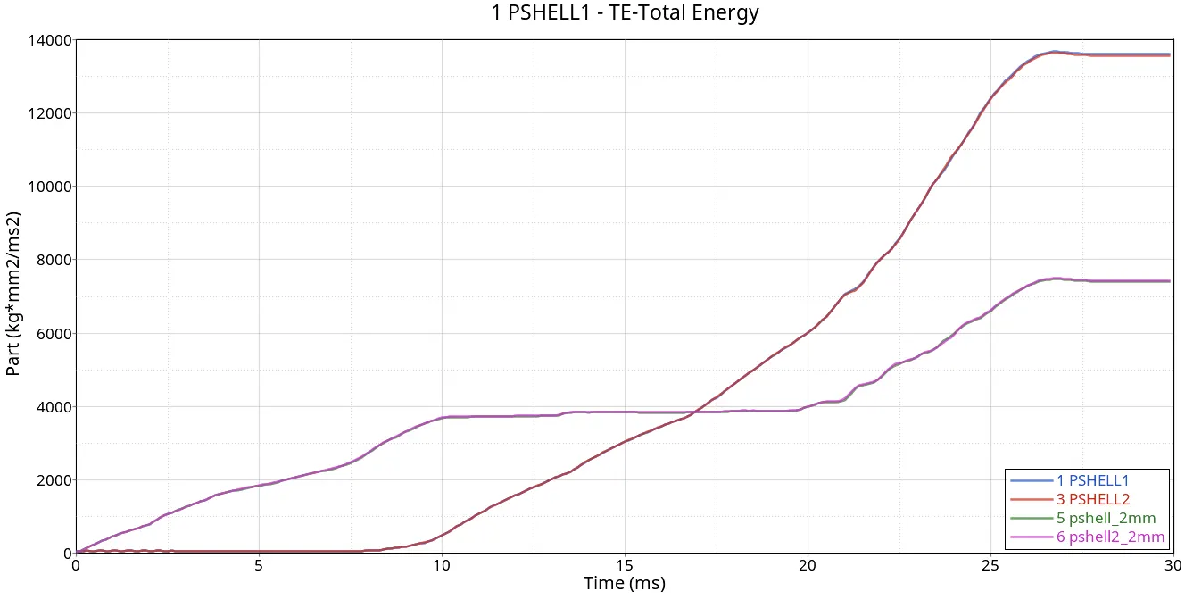
The above four graphs are plotted for each & every individual part gone through. Where the parts with 2mm thickness got deformed first, they are the parts that absorbed energy where the notches are affected by applied force in the form of bending initiated at that area.
------------------------------------------------------------------------------------------------------------------------------------------------------
CASE-2:-
Now we have to change the type -7 inacti to 6 and set all properties.
Step-1:
Import the case-1 rad file and edit the parameters.
Properties of Type-7 contact:
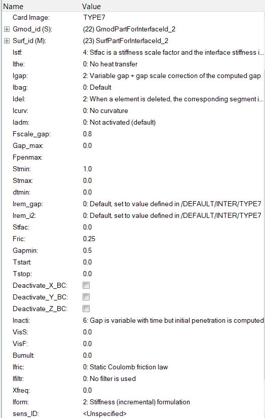
Then we are ready to run the simulation.
Step-2:
Energy and mass errors are in the acceptable range so we are good to plot the results.
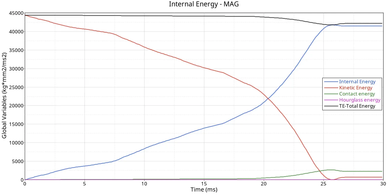
In the above energy graph, we can see the total kinetic energy is converted into internal energy, where the total energy is in a straight line around up to the 26th second while at that point there is an increase in contact energy which is reflected in Total energy.
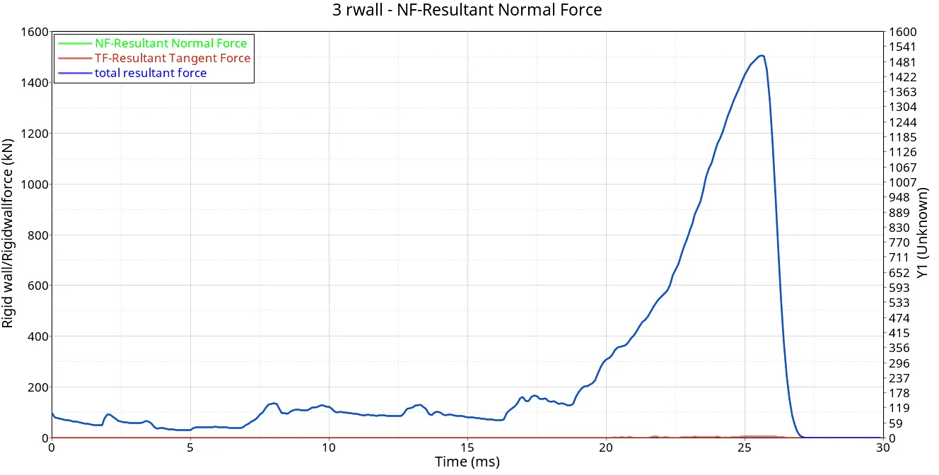
The total resultant normal force and total resultant force are all equal. At around 27 ms the component deformed fully and there is no chance to absorb energy by it.
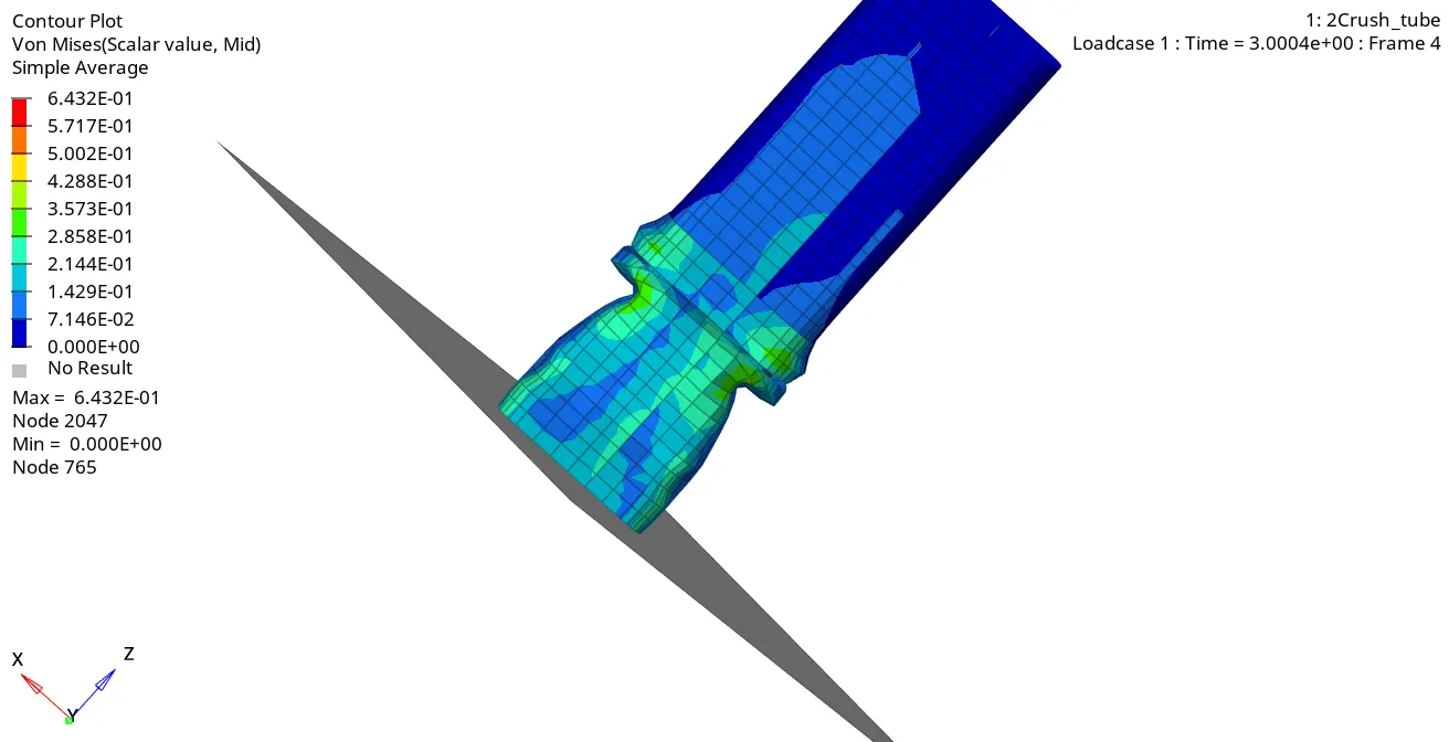
Here too the deformation started at round notch.
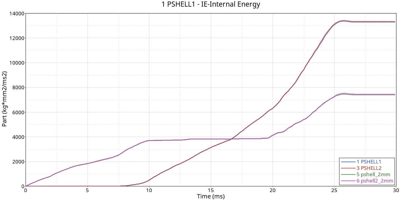
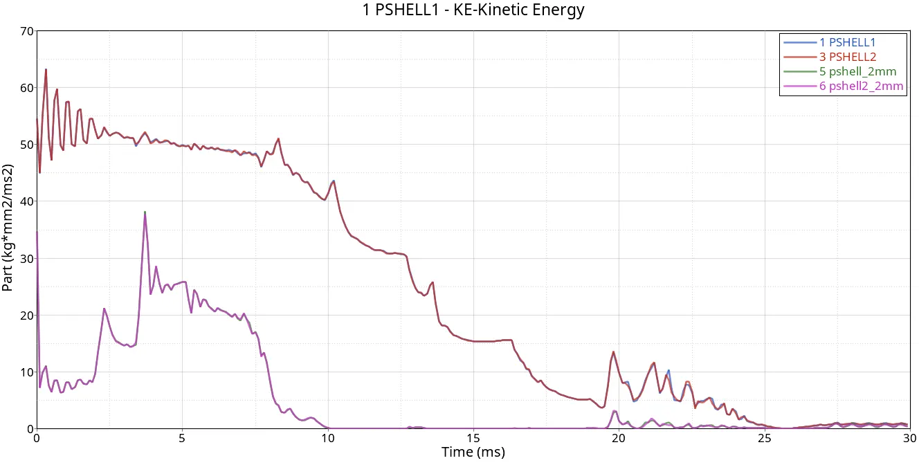
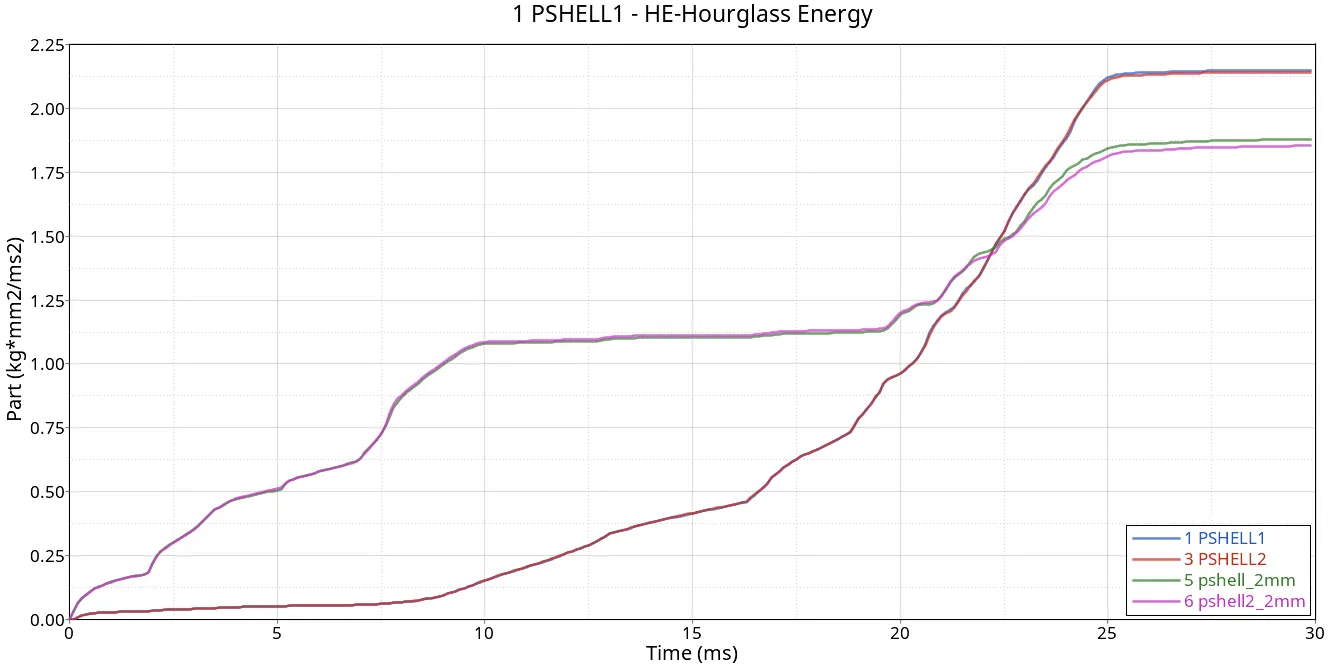
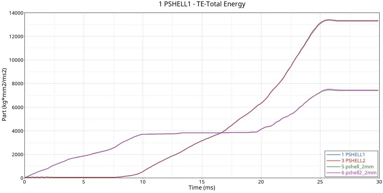
These are the plots of every part gone through. the part with a minimum thickness of 2mm started to deform with a strong reason for having notches in that region.
------------------------------------------------------------------------------------------------------------------------------------------------------
CASE-3:-
We need to create a Type-11 contact and need to simulate it.
Step-1:
Import the case-1 rad file and edit the parameters.
Properties of Type-11 contact:
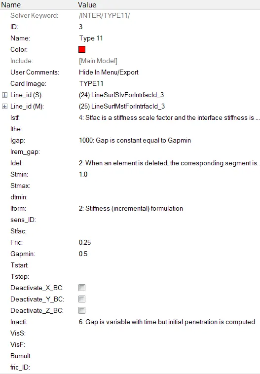
Now we are ready to run this case.
Step-2:
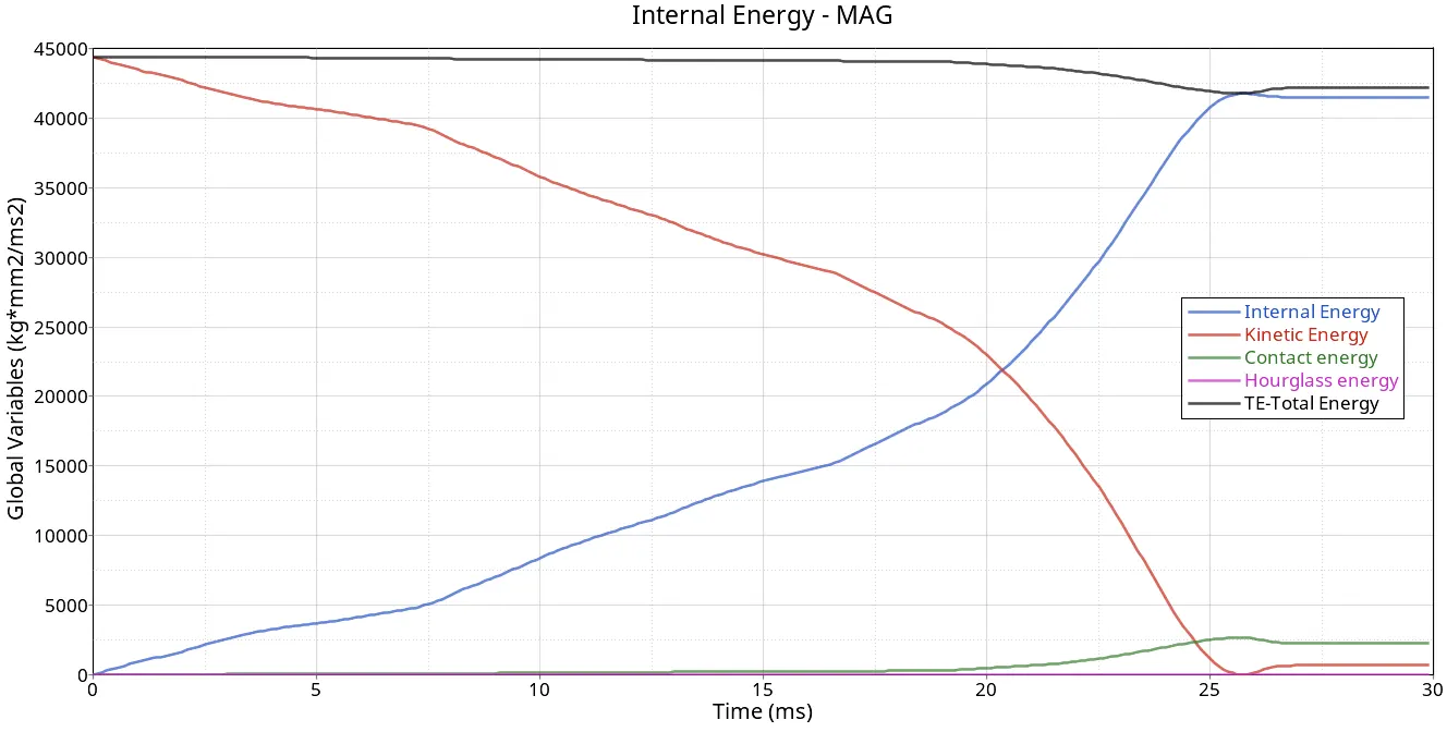
There is some slight change in internal energy at the end, which can be a good reason for recognizing the applied Type-11 contact condition.
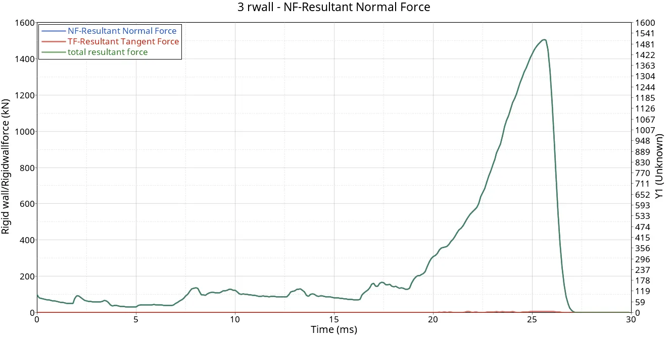
The energy absorption is pretty same in this case too, after 27 ms there is no chance of absorption of energy.
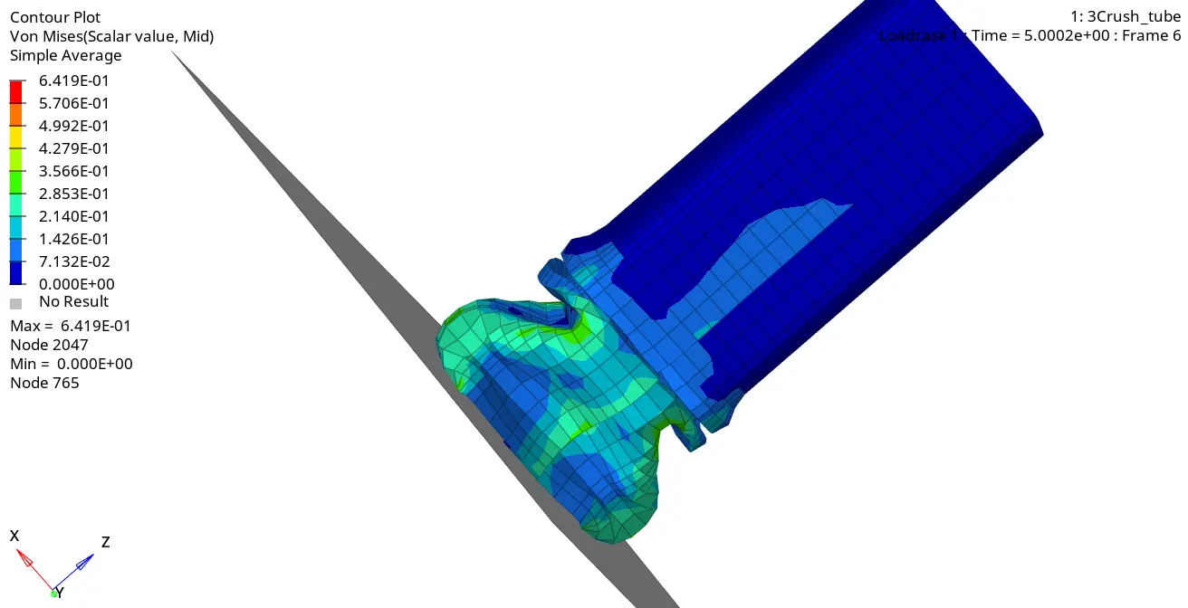
The max stress value is slightly low compared to cases 1 and 2 the deformation takes place at the initial notches area which gets bent when force is applied.
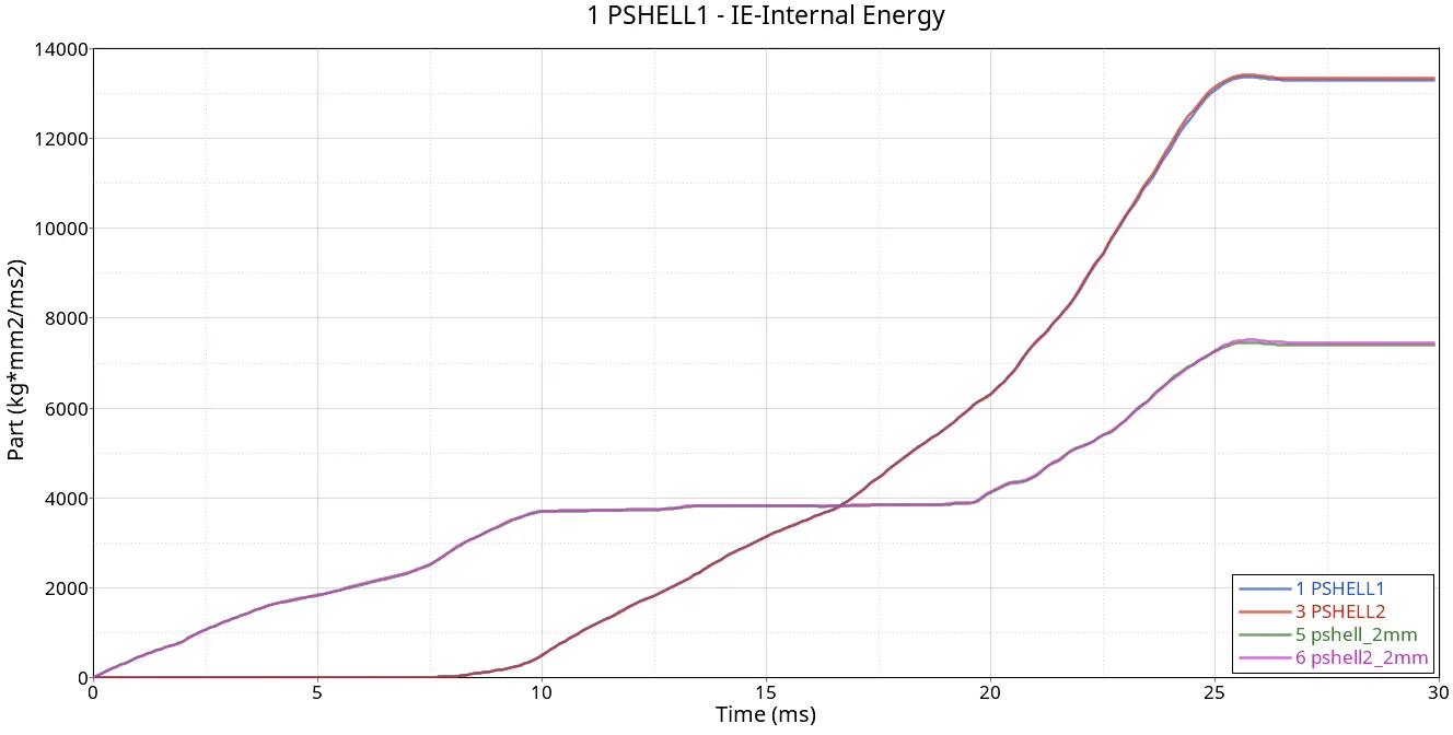
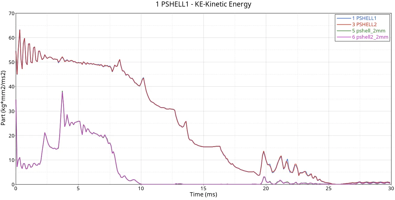
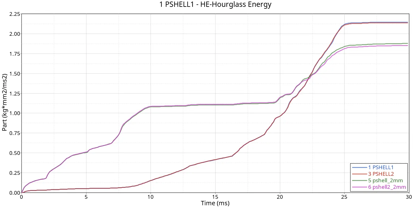
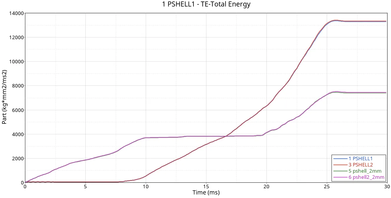
Here are the plots of individual parts, The plots are similar to cases 1&2.
-------------------------------------------------------------------------------------------------------------------------------------------------------
CASE-4:-
In this case, we need to remove all the notches then the boundary conditions of the rigid body also need to be deleted.
Step-1:
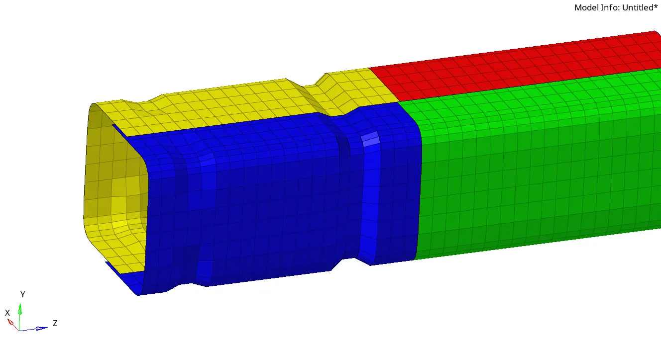
This is the model which we imported. we need to clear the notches.
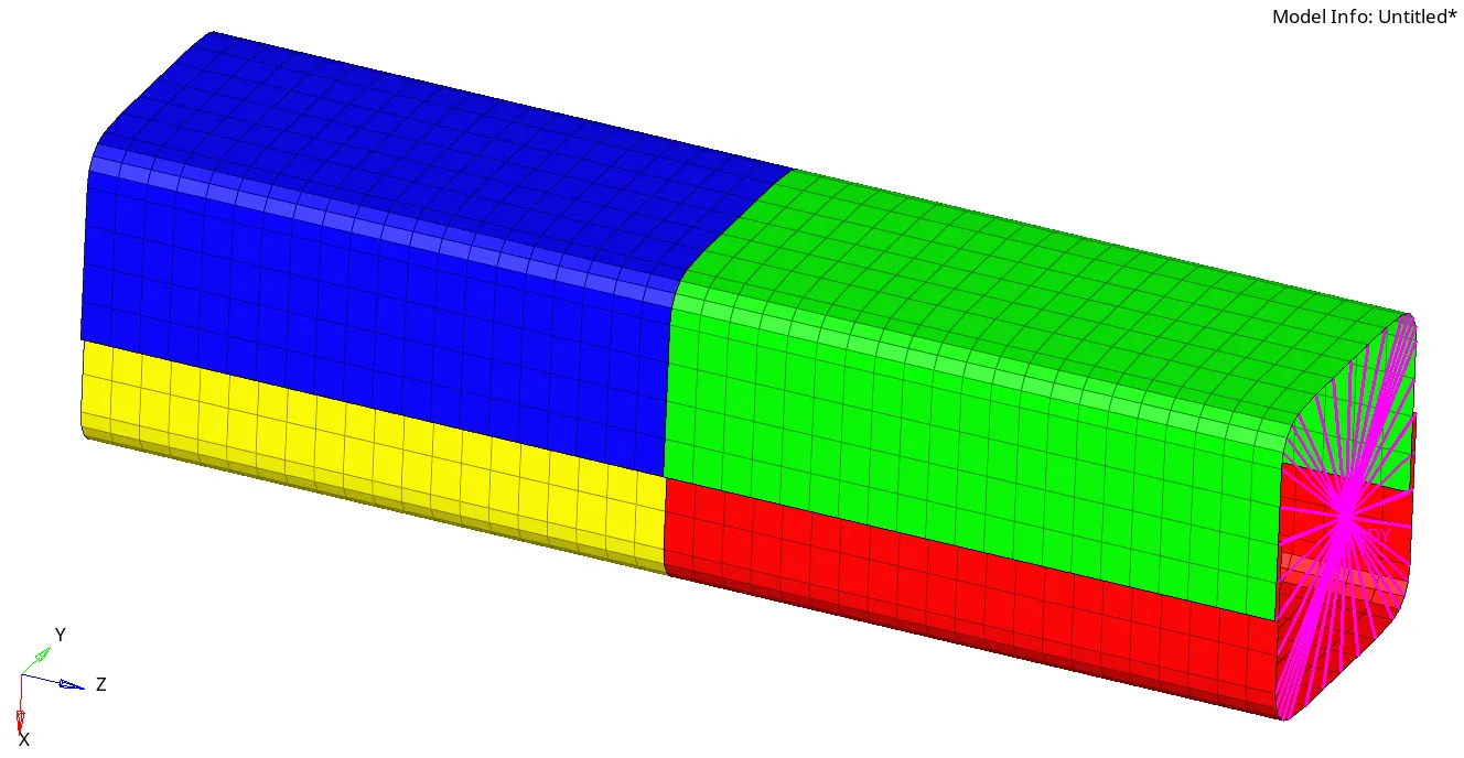
We can see the surfaces are fully flat without notches.
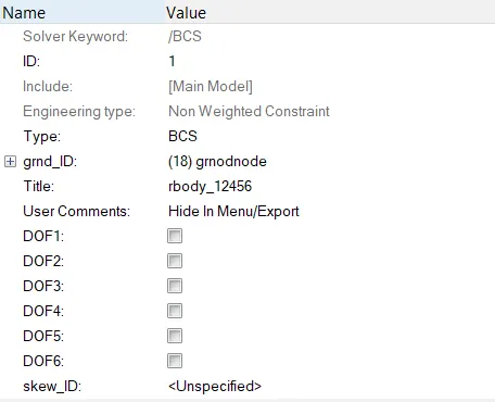
As per the condition in this case the boundary conditions are free in all directions.
Step 2:
As the energy error and mass error are in the acceptable regions we are good to go for plotting the results.
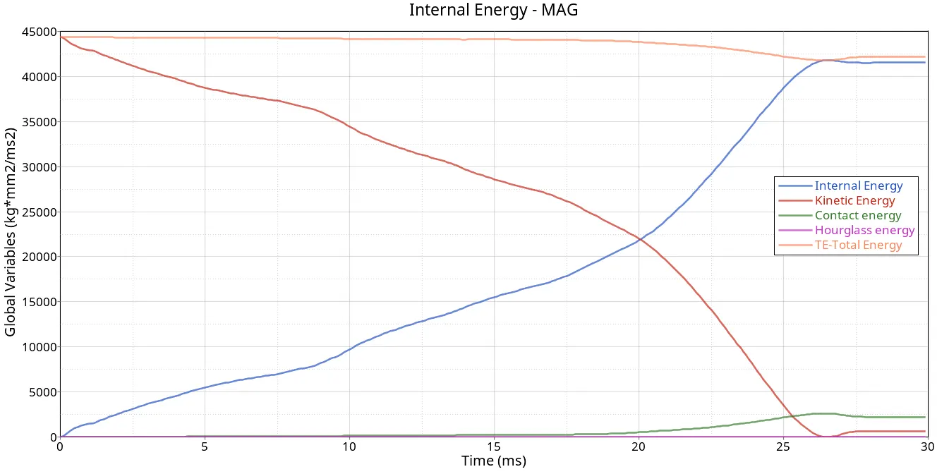
Here there is an increase in Contact energy and a very small portion of Hourglass energy too which affects the total energy.
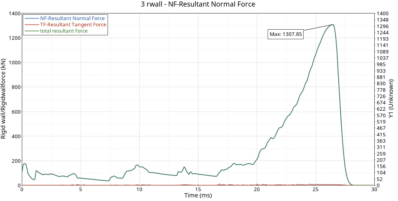
We can observe the maximum total resultant force is 1307.85 KN at around 26 ms. This recorded force value is low comparitively between 2&3 cases.
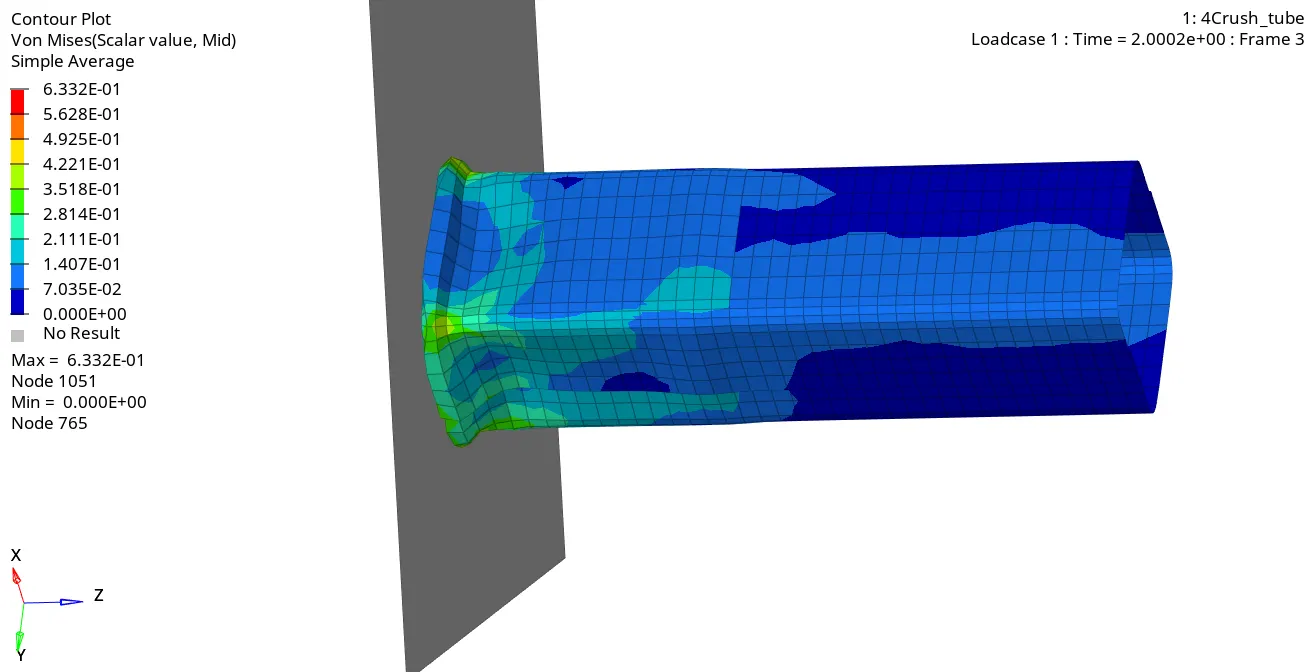
As there are no notches the initial deformation started at the hitting zone area because that part's thickness is 2mm and they are the first components to hit the wall.
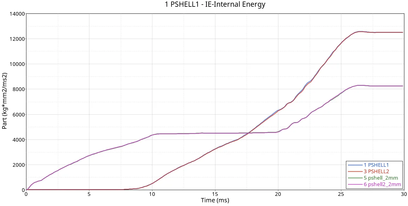
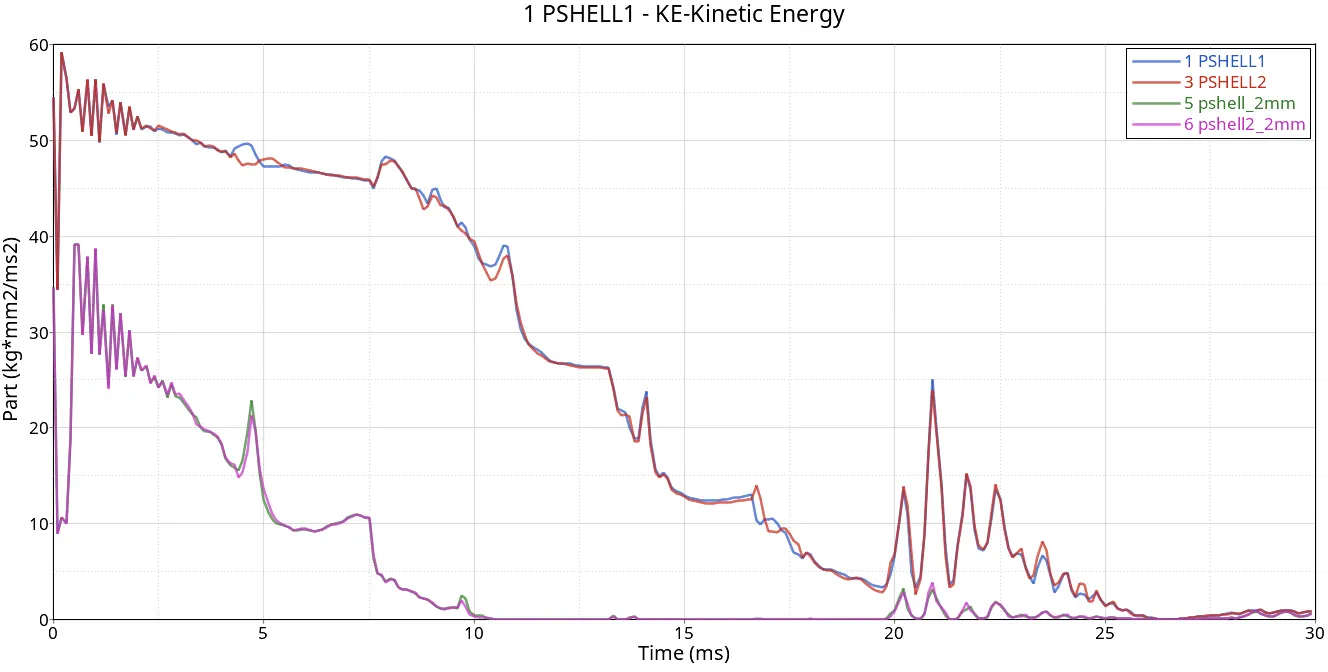
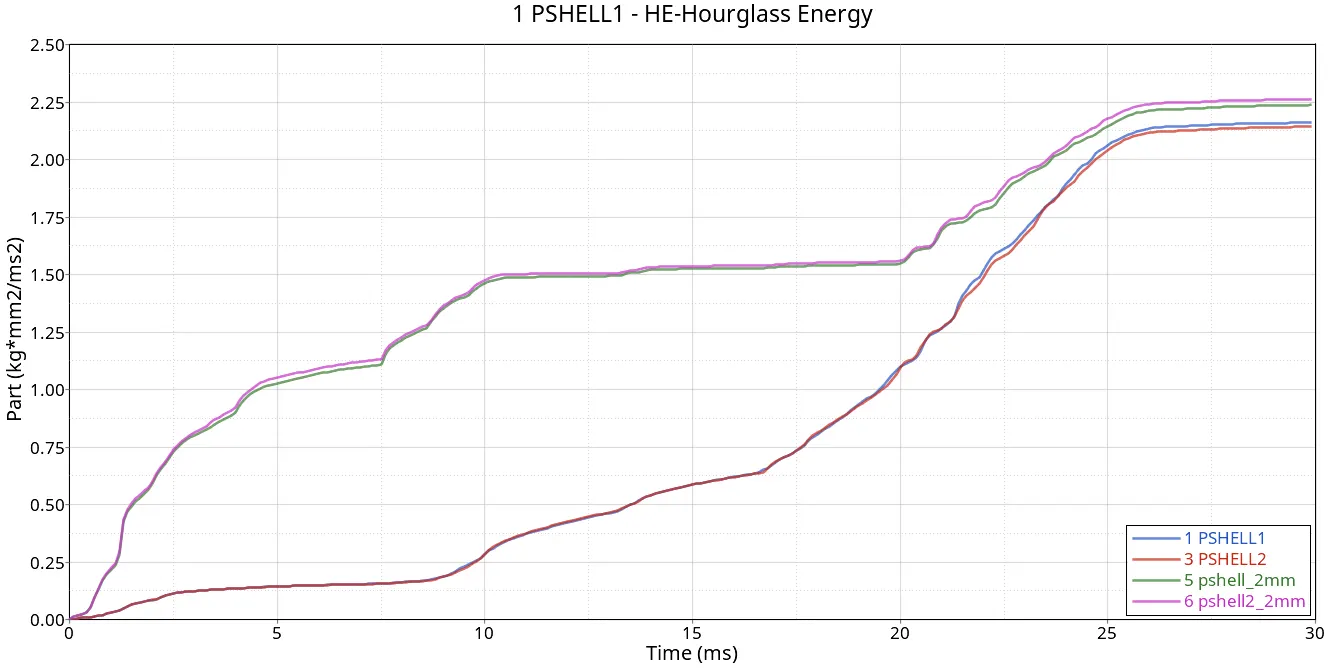
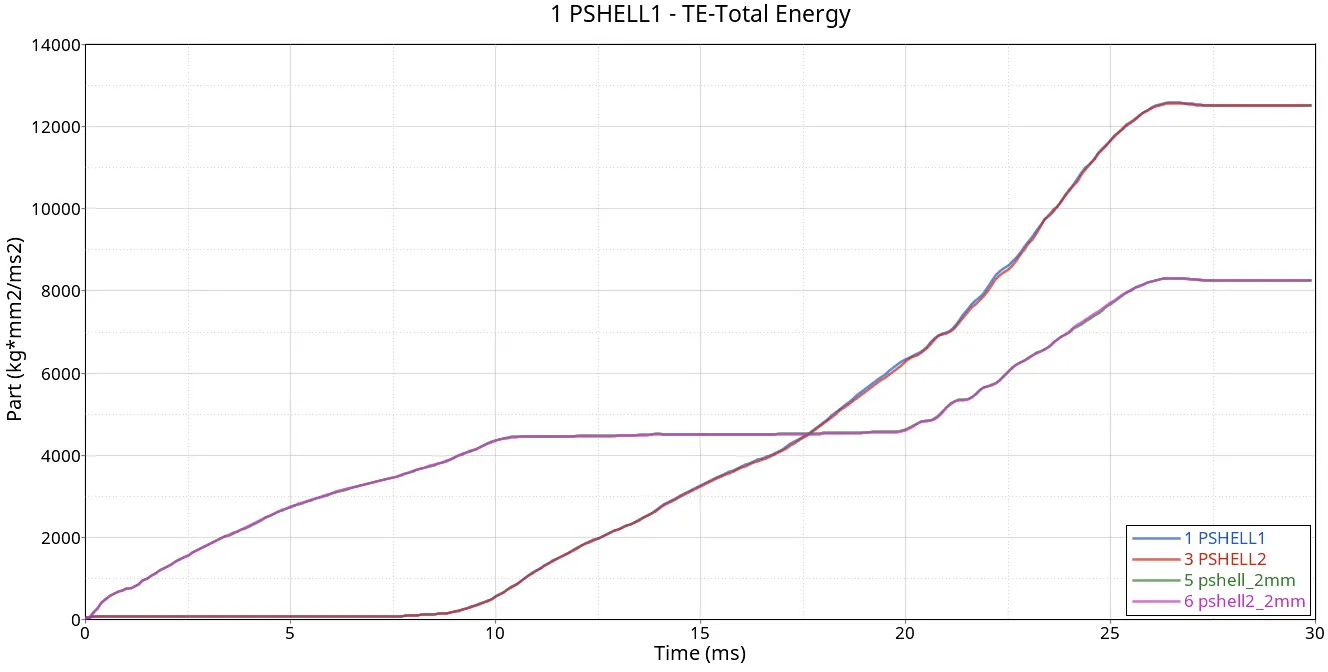
There is a drastic change when compared to case-1,2&3 of individual parts.
------------------------------------------------------------------------------------------------------------------------------------------------------
CASE-5:-
We need to create a round-notch in this case.
Step-1:
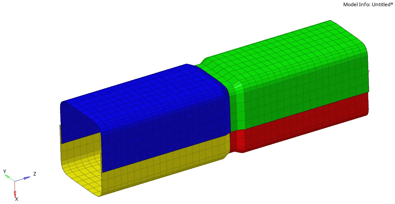
Here by imported the case 4 rad file and created a round notch at the middle portion as per the scenario.
Step-2:
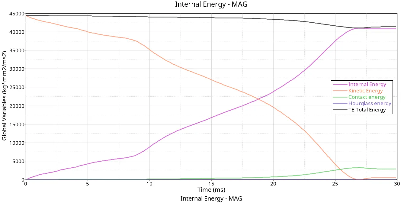
There are slightly faster reactions when compared to above all cases and a slight increase in contact energy.
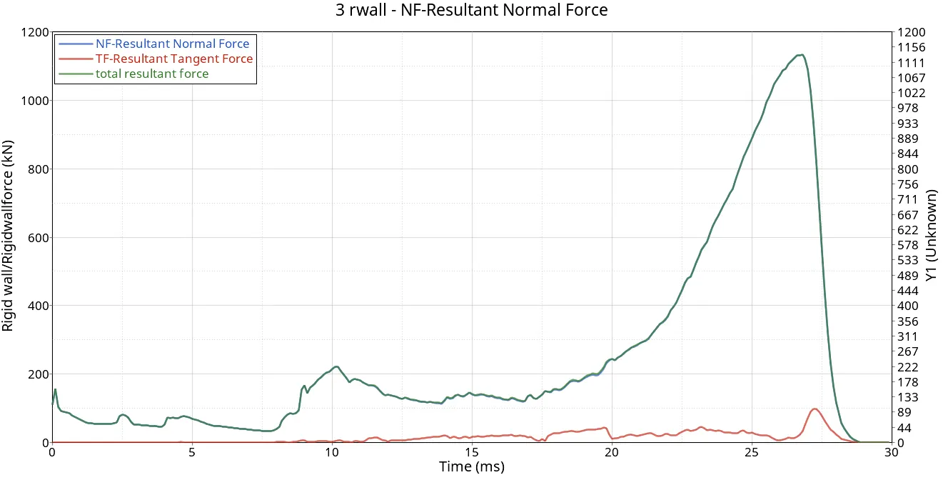
Here there is a very similar way of force absorption compared to the above cases but the max total resultant force of 1322.82 KN at around 24 ms.
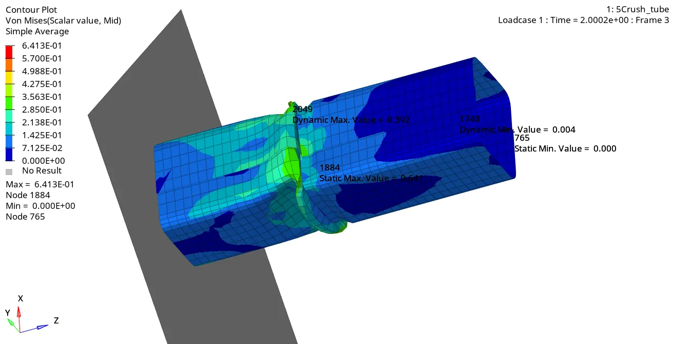
We can see the initial deformation started at the circular notch which we created for this case.
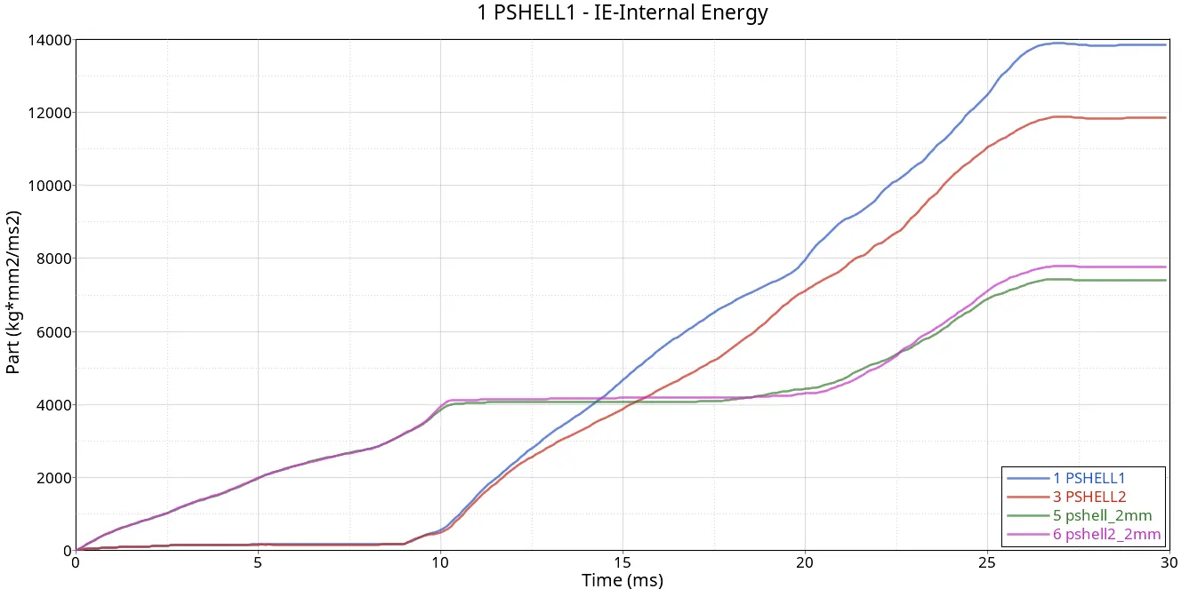
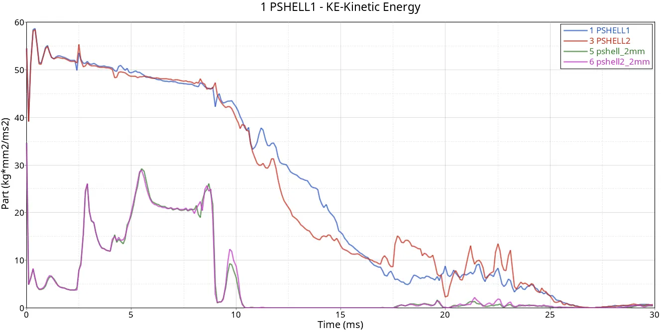
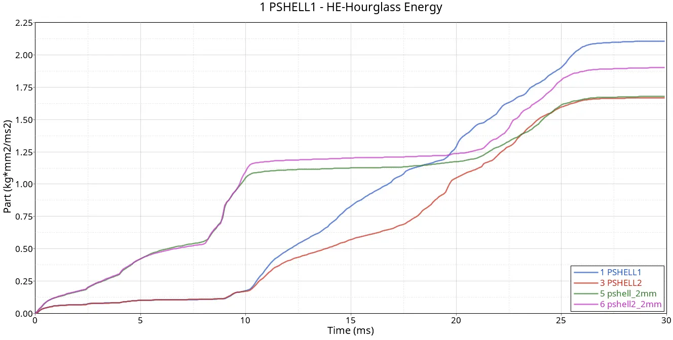
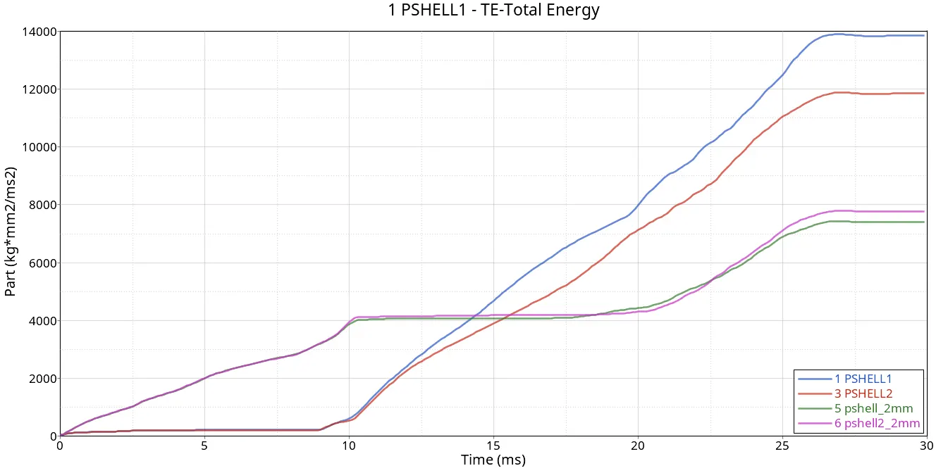
These are the graphs plotted for individual parts in this scenario. Part- with min thickness affected first along with the notch area.
------------------------------------------------------------------------------------------------------------------------------------------------------
CASE-6:-
In this case, we need to create opposite notches on the surface.
Step-1:
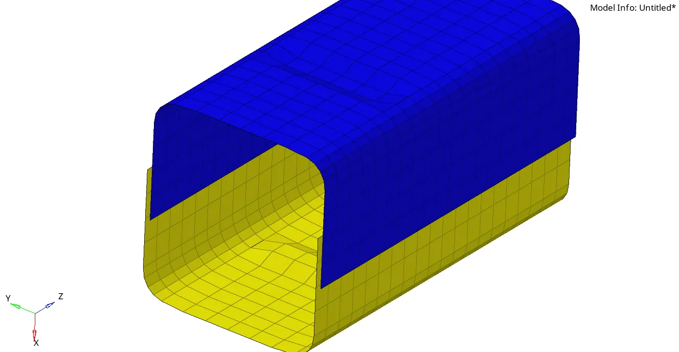
Here, in this case, opposite notches are made on the front surfaces.
Step-2:
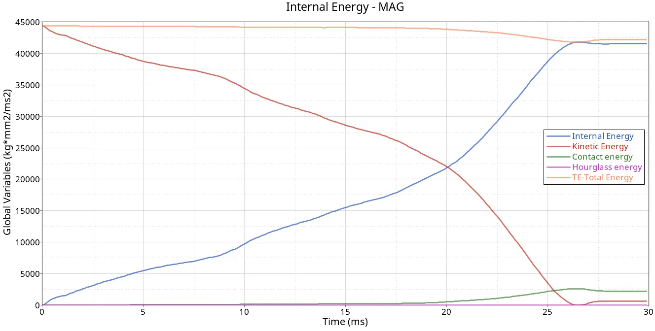
The results for energies are similar to the above cases where all show differences in the sudden deformation of the tube and reaction force by hitting the wall.
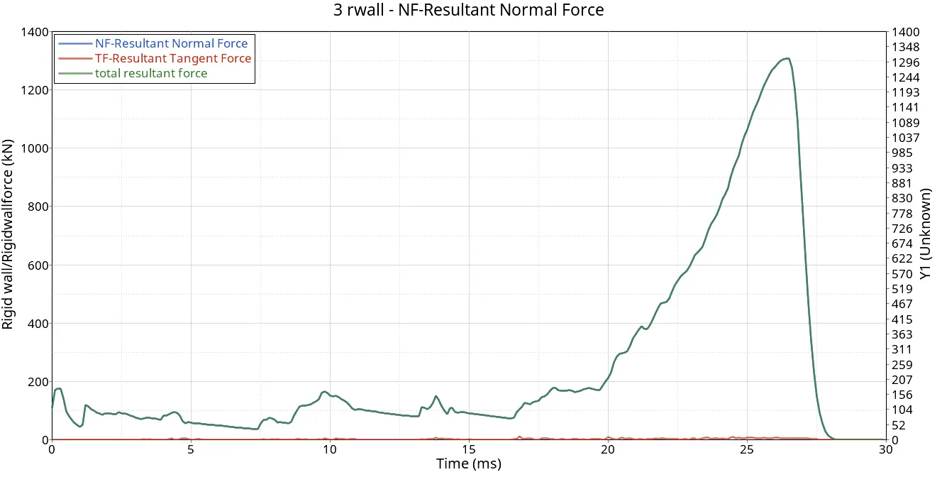
A sudden spike results in absorbing total applied force all of a sudden and then there is no chance to absorb force after around 27 ms.
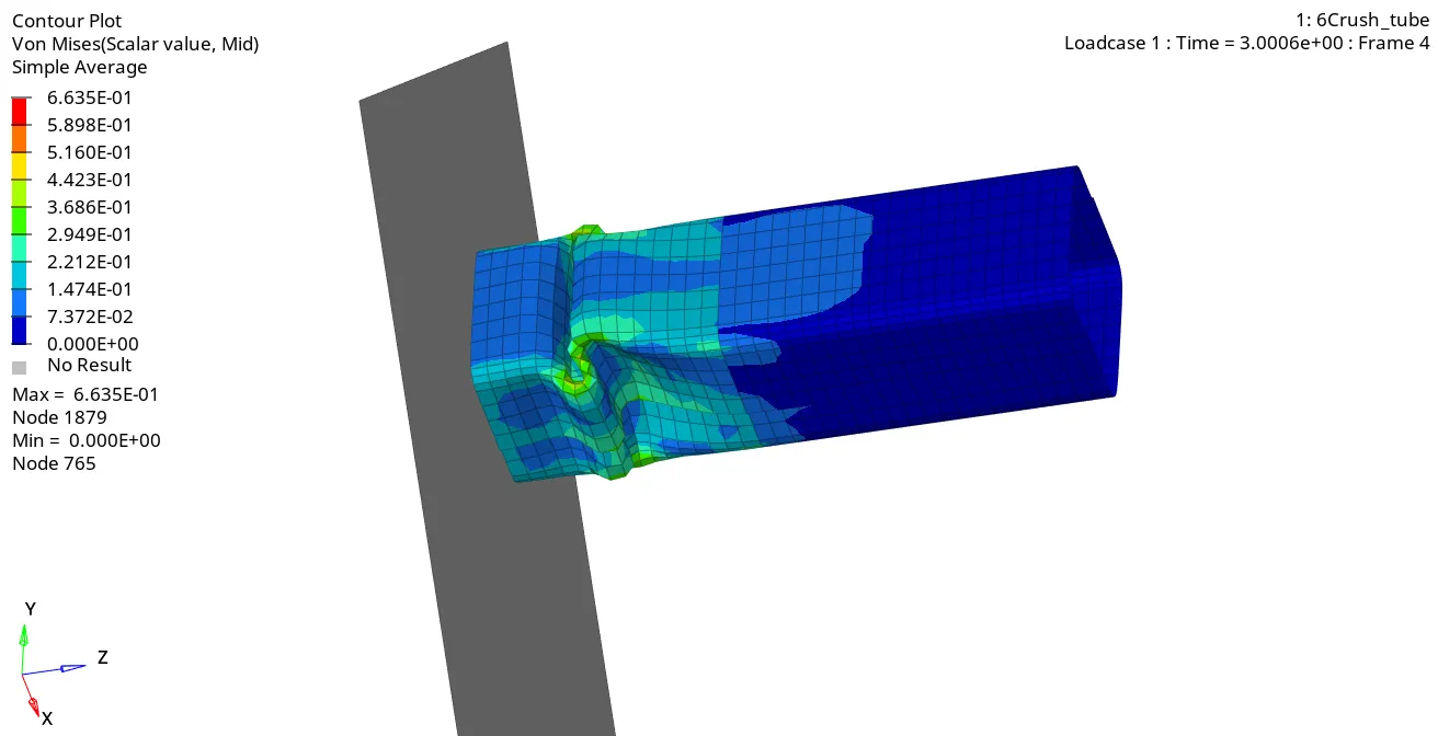
Here the notch area started to deform and a lot of force was converted into strain energy from there onwards.
The individual parts plots show a significant impact on the thin surface absorbing the energy first in the form of deformation.
-------------------------------------------------------------------------------------------------------------------------------------------------------
CONCLUSION:-
By simulating all the cases I got to know that notches played a key role in deforming the structure and also type-11 contact made the results to give more precise values.