Assignment 3-2D Element Formulation Challenge
OBJECTIVE:-
To compare the results with base simulation and improved shell element properties to understand the results & significance of the properties in the analysis.
Procedure:-
Case-1: Running the analysis with base properties.
Step-1:
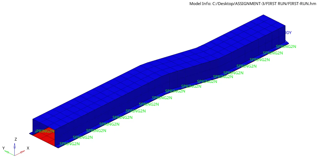
Imported the given model in Radioss.
Step-2:
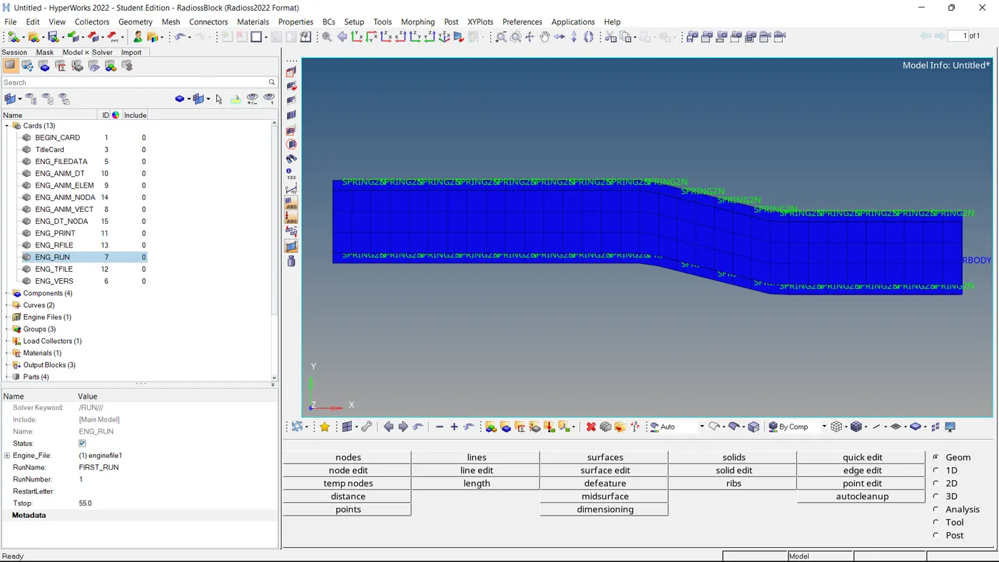
Setting of Run Time to 55 ms.
Step-3:
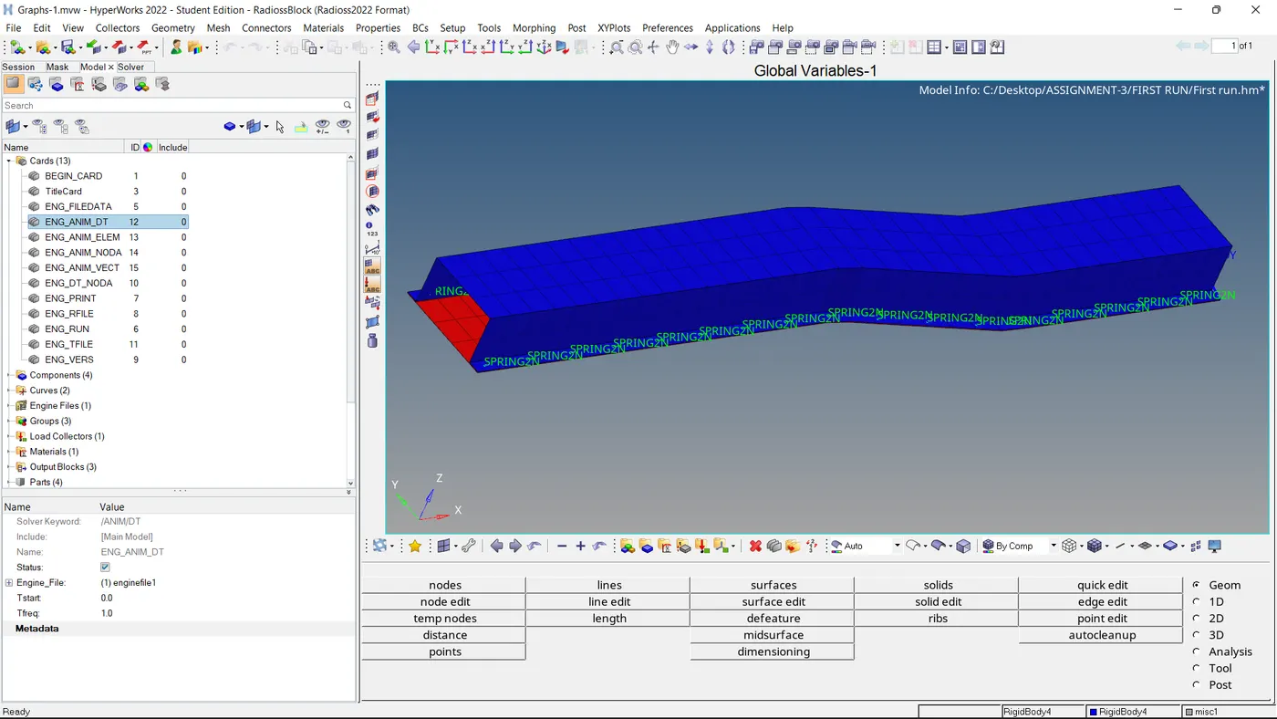
Set the number of animation steps during simulation to a minimum of 25 and a maximum of 60 as mentioned.
Step-4:
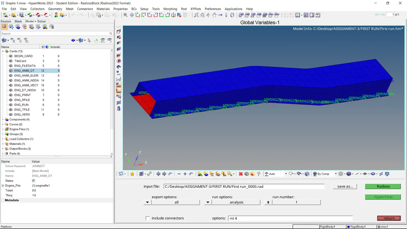
Run the simulation without changing the elemental properties.
Step-5:
CYCLE TIME TIME-STEP ELEMENT ERROR I-ENERGY K-ENERGY T K-ENERGY R EXT-WORK MAS.ERR TOTAL MASS MASS ADDED
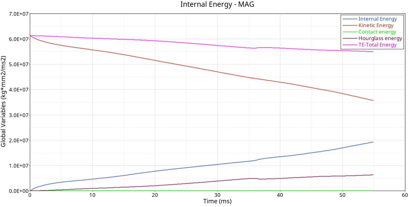
29210 55.00 0.1965E-02 NODE 711 -10.3% 0.1933E+08 0.3562E+08 0.2188E+05 -3980. 0.1659E-03 0.5040E+06 83.59
The energy error and mass error in ranges are acceptable as the error is 5%> -10.3%> -15%.
Step-6:
Plotting of results for rigid wall forces, internal energy, hourglass energy, contact energy, and total energy of the simulations.
Plot-1:
Plot-2:
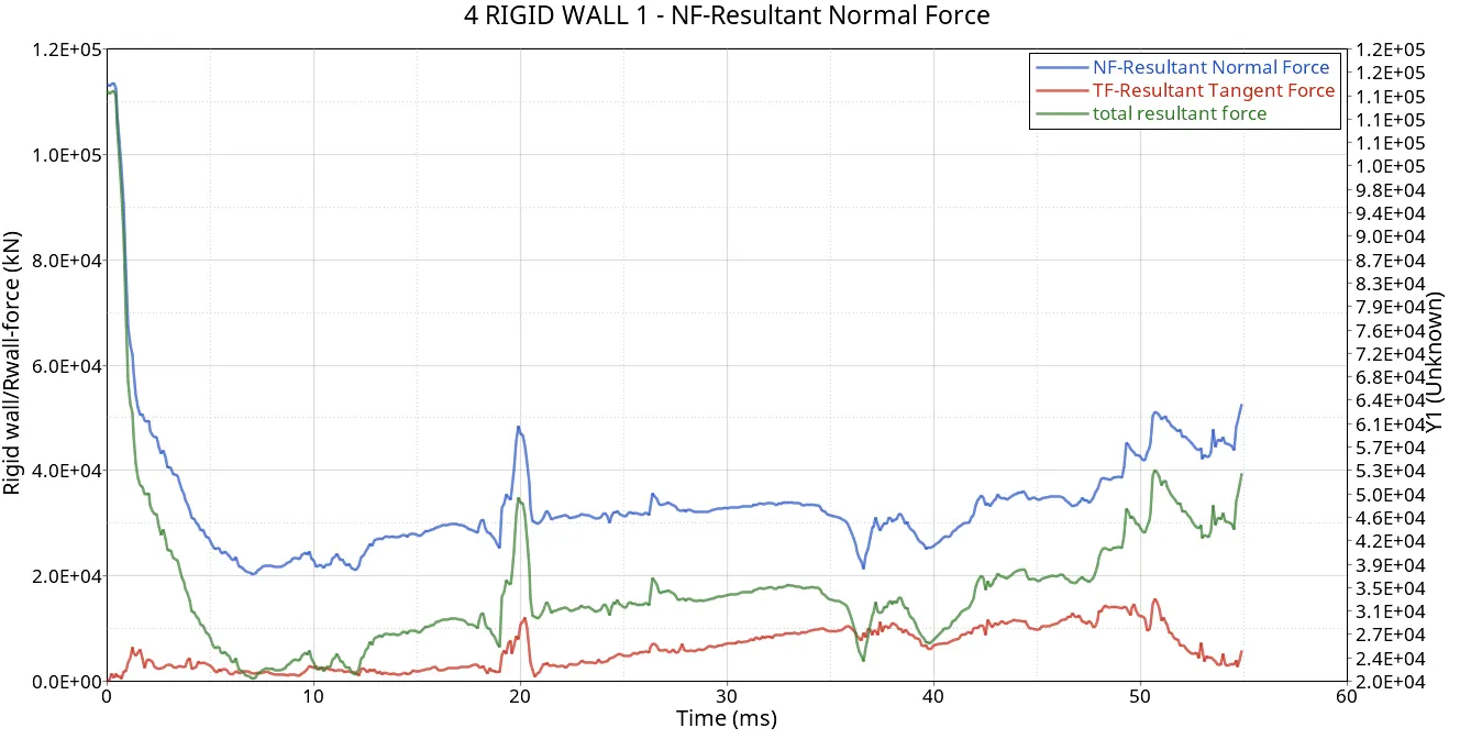
----------------------------------------------------------------------------------------------------------------------------------------------------------------------------------------
CASE-2: Running the analysis with improved shell elements properties.
Step-1:
Import the model in Radioss.
Step-2:
Setting of Run Time to 55 ms.
Step-3:
Set the number of animation steps during simulation to a minimum of 25 and a maximum of 60 as mentioned.
Step-4:
Now change the elemental properties before running the analysis.
| Parameters | Comment | |
|
Ishell =24 |
QEPH 4-node shells are the best combination of cost and accuracy. | |
|
Ismstr=2 |
Full geometric nonlinearities (default)with possible small strain formulation activation in RADIOSS Engine. | |
|
Ish3n=2 |
Standard 3 noded shell (C0)with modification for large rotation(default) |
|
| N=5 | Number of integration points is set to 5 for accuracy bending. | |
|
Ithick=1 |
Thickness change is taken into account for accuracy. |
|
|
Iplas=1 |
Iterative plasticity for good accuracy. |
Step-5:
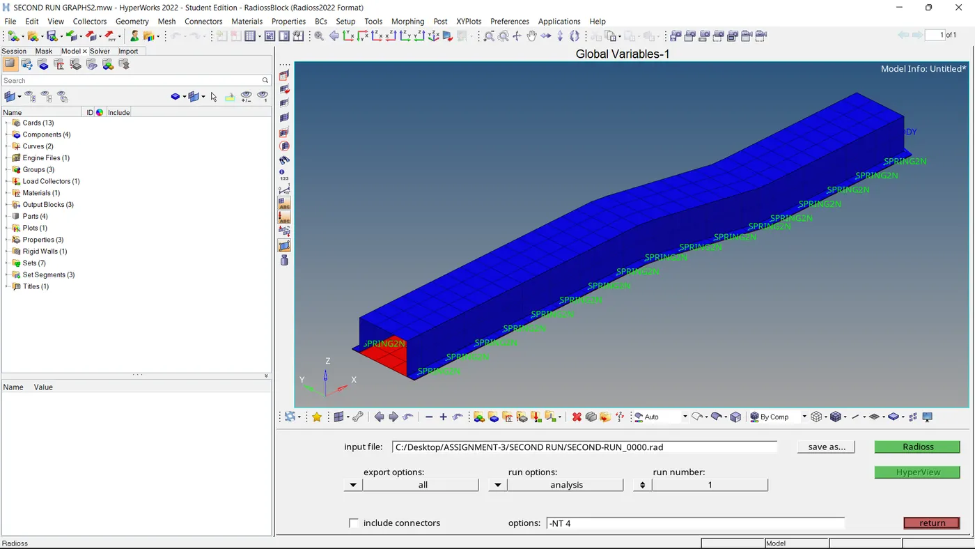
Now running the analysis.
Step-6:
CYCLE TIME TIME-STEP ELEMENT ERROR I-ENERGY K-ENERGY T K-ENERGY R EXT-WORK MAS.ERR TOTAL MASS MASS ADDED
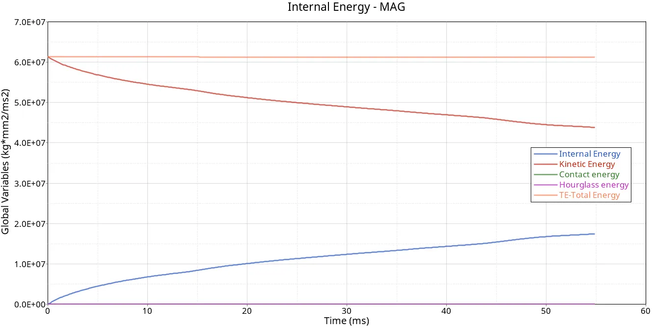
28990 54.99 0.1794E-02 NODE 708 -0.1% 0.1749E+08 0.4377E+08 3361. -1089. 0.1659E-03 0.5040E+06 83.59
The energy error and mass error in ranges are acceptable as the error is 5%> -0.1%> -15%.
Step-7:
Plotting of results for rigid wall forces, internal energy, hourglass energy, contact energy, and total energy of the simulations.
Plot:-1
Plot-2:
-----------------------------------------------------------------------------------------------------------------------------------------------------------------------------------------
Comparing the results of Case-1&2:
1) Plots of Internal Energy:-
CASE-1 CASE-2
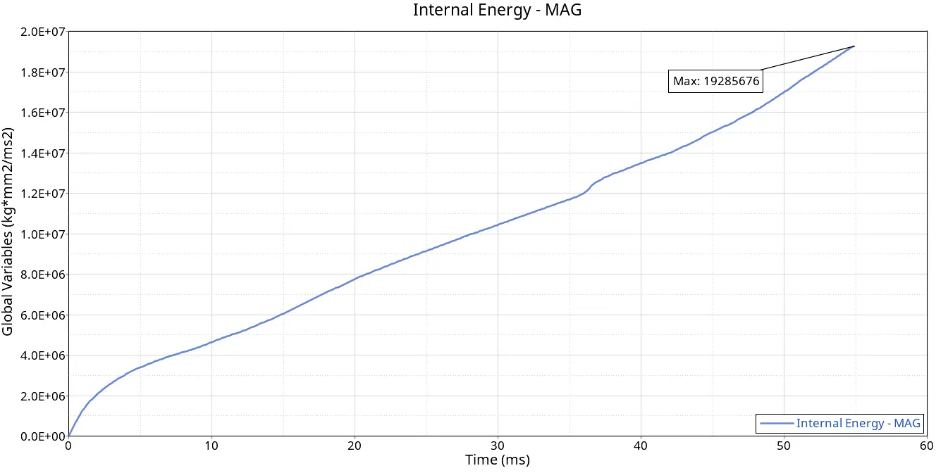
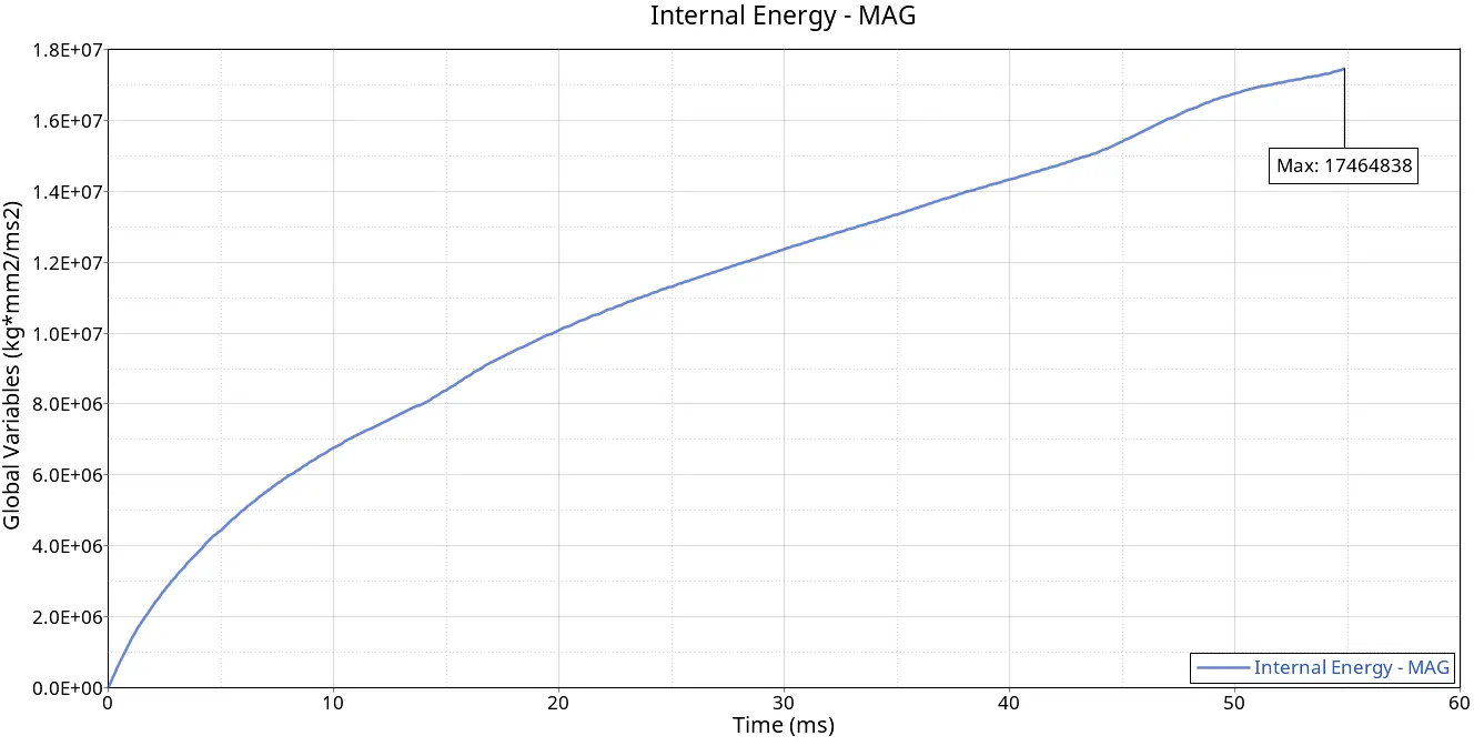
Internal Energy:-
Definition: Internal energy refers to the energy stored within a system due to the deformation of its elements.
Explanation: In FEA, internal energy is associated with the strains and stresses in the material. As the finite elements deform, they store and release energy in the form of elastic deformation. This energy is calculated based on the material properties and the deformation of the elements.
Because of the change in elemental properties like I small strain, it showed its impact as the elements change their location and deform which are related to the calculation of the Shape function and Gaussian integration points kept on updated during the analysis which had given us more precise results.
2) Plots of Kinetic Energy:-
CASE-1 CASE-2
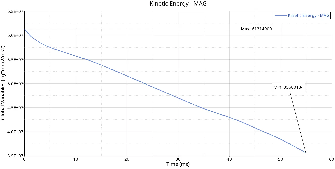
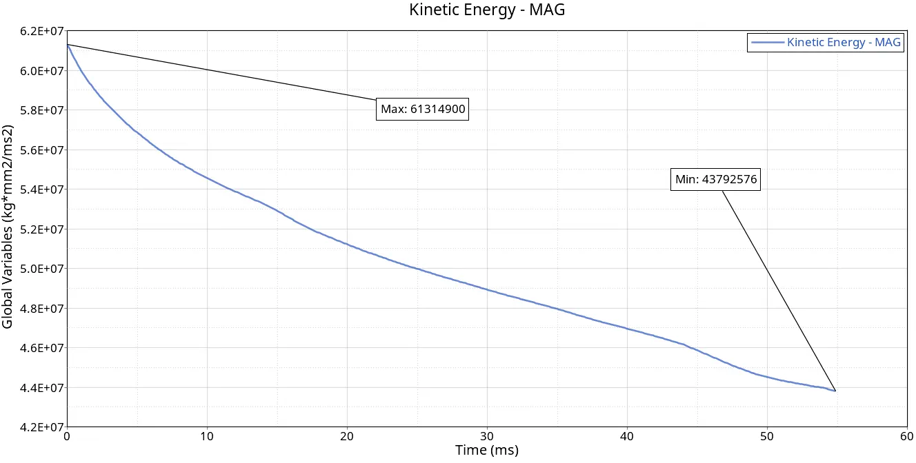
Kinetic energy:
Definition: Kinetic energy is the energy associated with the motion of the mass in a system.
Explanation: In the context of FEA, kinetic energy is relevant in dynamic simulations where the structure is subjected to time-varying loads. It represents the energy associated with the movement of the structure's mass and is calculated based on the velocities of the nodes in the finite element model.
Kinetic energy is related to, if energy absorption is the goal then most of the kinetic energy is converted into internal energy. This means that the analysis started with a huge initial velocity and when it started the resistance force from the Rigid wall and the structure got buckled at one time where the structure started to form kinks at the bending portion of the structure resulting in the increase in the contact area and formed a linear deformation as the increase in internal energy.
3) Plots of Contact Energy:-
CASE-1 CASE-2
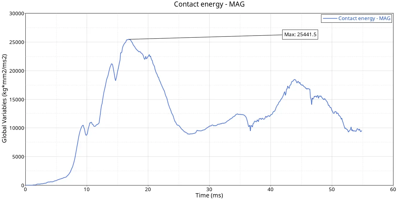
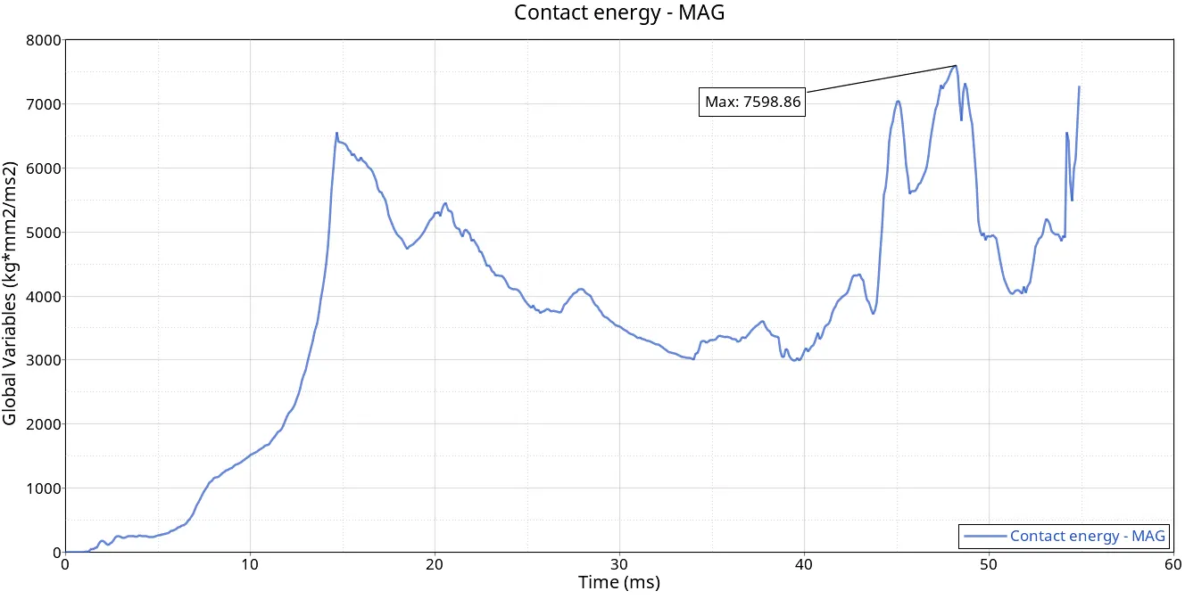
Contact Energy:-
Definition: Contact energy refers to the energy associated with interactions between different parts or surfaces in a simulation, where contact forces and deformations are considered.
Explanation: In FEA simulations involving multiple surfaces or components, there may be contact between them. Contact energy accounts for the work done and energy exchanged during contact interactions. This is particularly relevant in simulations where parts may come into and separate from contact during the analysis.
Here too the same scenario the change in I small strain elemental property results in proper calculation on basing the actual conditions.
4) Plots Hourglass Energy:-
CASE-1 CASE-2
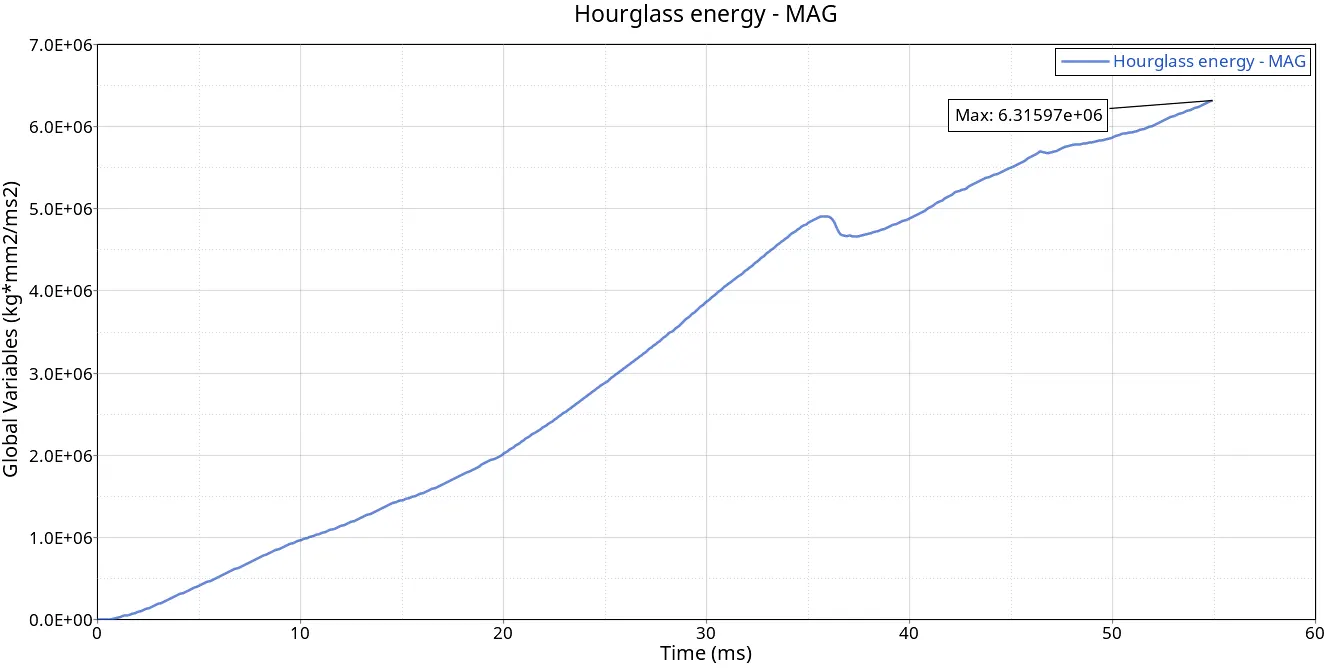
Hourglass energy:
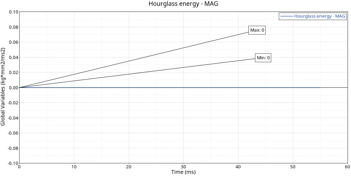
Definition: Hourglassing refers to a type of deformation mode that can occur in certain types of finite elements during analysis. It is an unwanted and often artificial distortion that can compromise the accuracy of FEA results. Where to control elemental deformation with zero stress recordings.
Explanation: To stabilize the numerical solution and suppress hourglassing modes, an artificial energy term known as hourglass energy is introduced into the FEA formulation.
As we change the I shell value to QEPH 24 it is an improved under-integrated 4-node element with 1 integration point on the surface and the hourglass effect is also controlled at the material level which will increase stiffness. As in case -1, it is not considered so it affected a lot.
5) Plots of Total Translation Energy:-
CASE-1 CASE-2
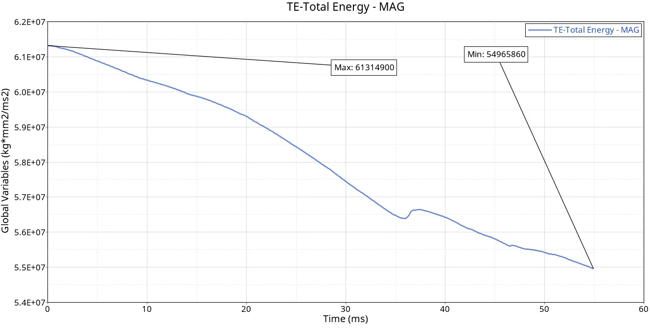
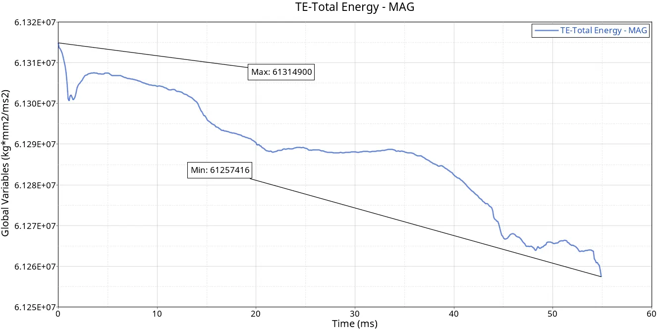
Total Translation Energy:-
Definition: Total energy is the sum of internal energy, kinetic energy, hourglass energy, contact energy, and any other relevant energy terms in the system.
Explanation: Total energy provides an overall measure of the energy state of the system being analyzed. It takes into account the actual physical energy stored in the material (internal energy), the artificial energy introduced for numerical stability (hourglass energy), the energy associated with contact interactions, and, in dynamic simulations, the kinetic energy of the moving masses.
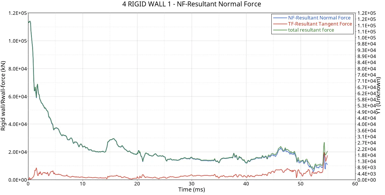
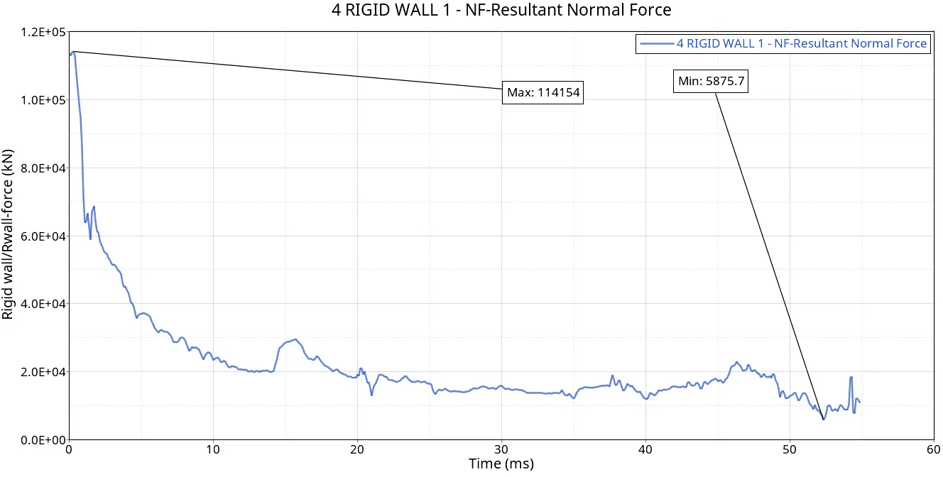
6) Plots of Resultant Normal Force:-
CASE-1 CASE-2
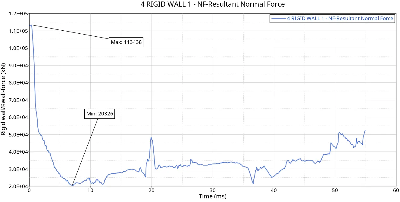
Resultant Normal Force:-
Definition: The resultant normal force represents the net force acting perpendicular to the surface of a finite element. It is a vector quantity, meaning it has both magnitude and direction.
Explanation: In FEA, the analysis involves the calculation of normal (perpendicular) forces that result from deformations and loading conditions. These forces are computed based on the stiffness of the elements and the displacements of their nodes. The resultant normal force provides insight into how the structure is experiencing compressive or tensile forces along its elements.
We can observe in the graphs a lot of difference between the maximum and minimum force values, We used the QEPH-24 elemental property with an improved under-integrated 4-node element with 1 integration point on the surface and I small strain property made the calculations work with updated values results to the resistance force from which is tackling with the applied force in the absorption of energy.
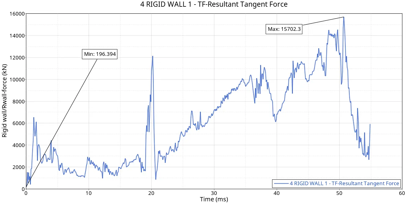
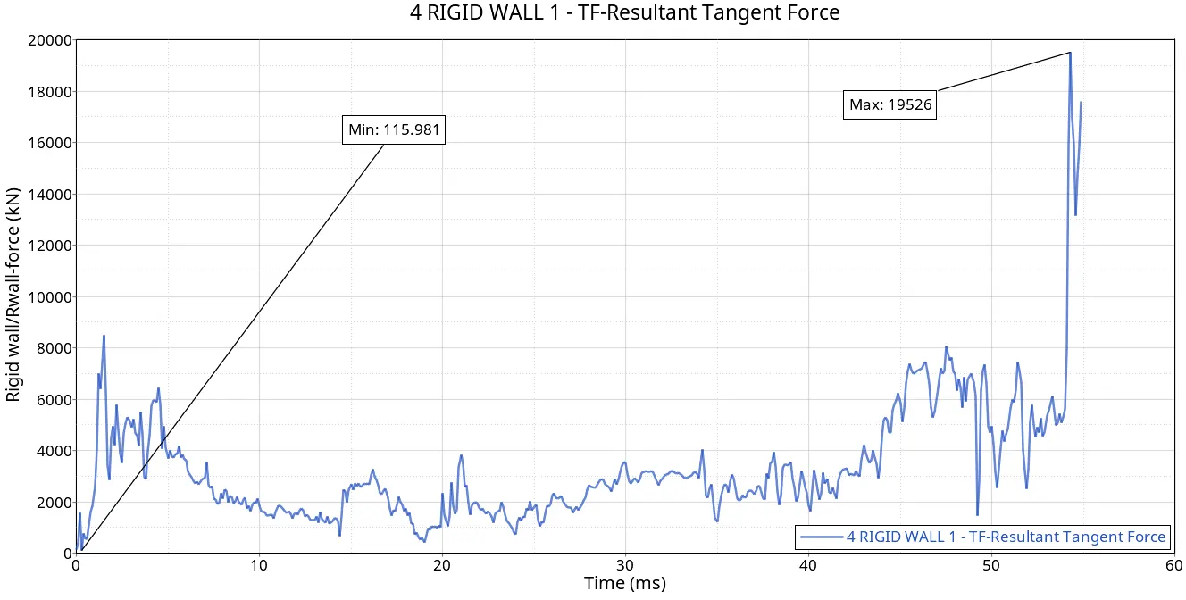
7) Plots of Resultant Tangential Force:-
CASE-1 CASE-2
Resultant Tangential Force:-
Definition: The resultant tangent force is the force acting tangentially on the surface of an element.
Explanation: Tangent forces are associated with the shear deformations within the elements. In FEA, the analysis considers how forces are distributed tangentially across the surface of the finite elements.
It is observed in the analysis when the force is applied towards the pipe it starts to crush it resulting in an increase in surface contact. If surface contact increases then the frictional force also increases it is what the plot expresses.
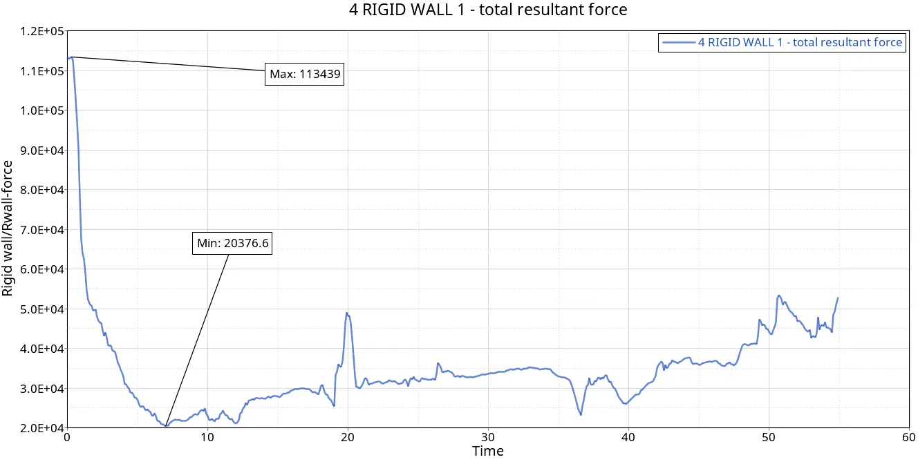
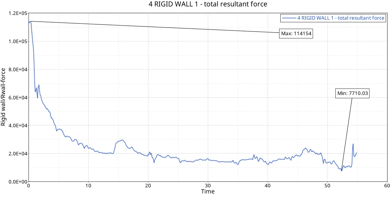
8) Total Resultant Force:-
CASE-1 CASE-2
Total Resultant Force:-
Definition: The total resultant force is the vector sum of the normal and tangent forces acting on an element.
Explanation: The total resultant force accounts for both normal and tangent forces, providing a comprehensive description of the forces experienced by an element. It considers the combined effect of axial (normal) and shear (tangent) forces. This total force is crucial for assessing the overall structural response and deformation of the system under given loads and boundary conditions.
CONCLUSION:
After observing the results, we can say that the elemental properties played a major role in getting the proper and precise results we needed. These elemental properties
| Parameters | Comment | |
|
Ishell =24 |
QEPH 4-node shells are the best combination of cost and accuracy. | |
|
Ismstr=2 |
Full geometric nonlinearities (default)with possible small strain formulation activation in RADIOSS Engine. | |
|
Ish3n=2 |
Standard 3 noded shell (C0)with modification for large rotation(default) |
|
| N=5 | Number of integration points is set to 5 for accuracy bending. | |
|
Ithick=1 |
Thickness change is taken into account for accuracy. |
|
|
Iplas=1 |
Iterative plasticity for good accuracy. |