Assignment 5
Aim:
- To create the mesh for bumper assembly by keepimng the mesh size as 6mm.
- To run the given model using the different cases given below and to study the difference from each case
Given Cases :
- Run the crash tube model as it is.
- Change the Inacti=6 and run.
- Create the type 11 contact and run.
- Remove both notches and remove boundary condition on rigid body node then run.
- Create a new notch in the middle ,select the whole section and run.
- Create a new notch with nodes only from opposing 2 faces and run.
Procedure :
Perform 2D meshing for the bumper model :
Step 1 :
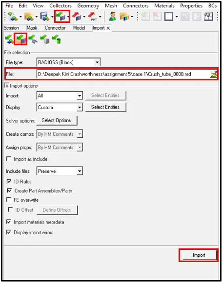
Import the given model into hypermesh using the import command:
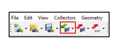
- Click on the import command on the tool bar.
- Select the appropiate file type from the drop down menu (i.e STEP, IGES or HYPERMESH).
- Browse the file which is required to import.
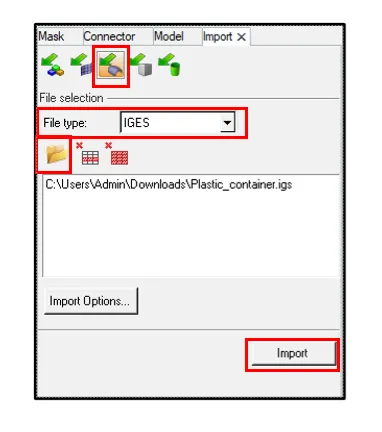
- Click import from the bottom and the required model will be displayed on the Hypermesh workbench.
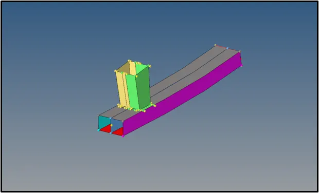
Step 2 :
Geometrical Cleanup and Topology of Midsurface :
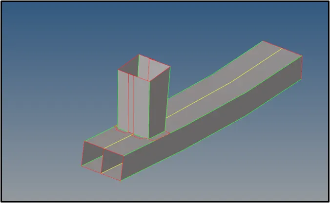
- Check for geomertrical errors in the midsurface.
- Check for missing surfaces and free edges and fix it using the neccessary tools.
- Use the Quick Edit panel to split surfaces and washers, change the category (shared, free, and so on) of edges, create or delete surfaces and points, project points, and trim fillets.
- Check for the surfaces that might fail for minimum length and defeature if required using the defeature tool.
- Use the Edge Fillets subpanel to identify and remove edge fillets. Similar to surface fillets, edge fillets create smooth curves at the intersection of relatively perpendicular free edges. You can identify them based on the radius of the fillet arc, and then remove them.
- Use the line toggle option to toggle lines wherever required.
- Use the replace point option, to move points from their current locations to the locations of other points, effectively combining them.

Step 3 :
Meshing the component :
Meshing is an integral part of the engineering simulation process where complex geometries are divided into simple elements that can be used as discrete local approximations of the larger domain. The mesh influences the accuracy, convergence and speed of the simulation.
- Use the Automesh option to generate a mesh of plate elements using surface geometry or existing shell elements to define the mesh area.
- Set the options in the panel in any order that you feel comfortable using. Moving from subpanel to subpanel will not cause you to lose work. When you are finished making all your selections, click mesh to start the meshing process.
- Set the panel mode by selecting the appropriate subpanel.
- Select the meshing method by setting the entity selector to surfs or elems.
- Make the required element criteria settings.
- Set any algorithm options.
- Select the area to be meshed using the entity selector and any extended selection methods.
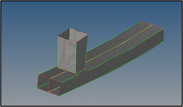

Procedure :
• Import the given file into hyperworks.
•The model will be imported.
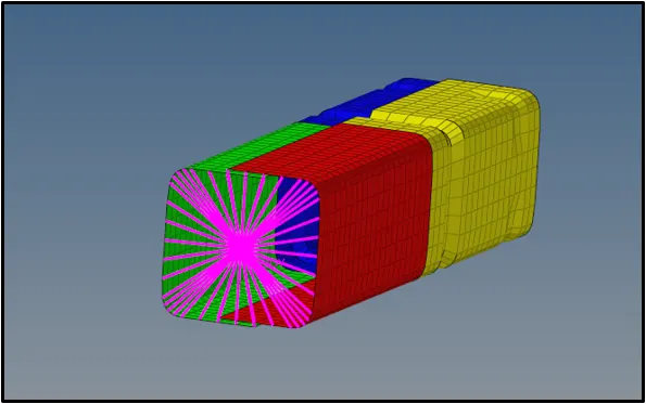
Case 1 : Run the crash tube model as it is.
Interface TYPE7 is a multi-usage impact interface, modeling contact between a master surface and a group of slave nodes. It is also possible to consider heat transfer and heat friction.
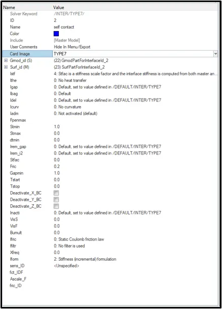
- Run the base simulation without changing any values.
- From the subpanel below, click on Analysis > Select the save location > click Radioss.
- Simulation will start.
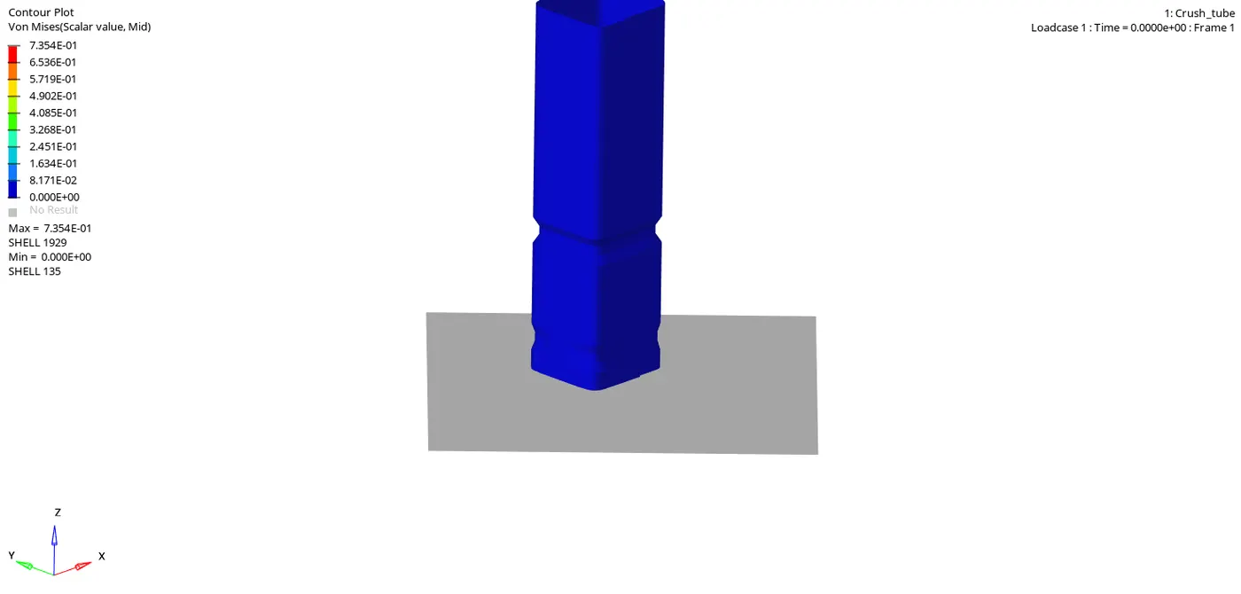
From the above simulation, the maximum stress acting was found to be 7.345E-01.
- At the end of the simulation, do the energy error and mass error checks and determine whether results would be acceptable
- Open the save location file and click on the output file of the simulation to check for the Energy error and Mass error.
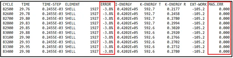
Maximum Energy error was found to be -3.8% and Maximum Mass error was found to be 0.
Plot the graph of rigid wall forces, internal energy, kinetic energy, contact energy of the simulations.
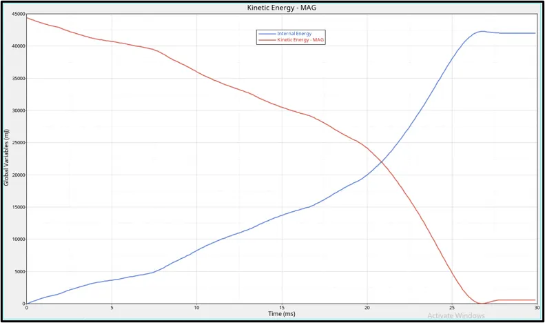
Initially, the kinetic energy will be high when the force is applied on the body. On the first impact, the crush tube starts to deform and the surrounding energy is stored in it. Because of this stored surrounding energy, the internal energy starts to increase. The kinetic energy decreases when the impact happens and the absorbed energy increases which inturn increases the internal energy. During maximum deformation, ther velocity will become zero and the kinetic energy will also dip down to zero. Due to this drop down in kinetic energy there will no ebergy to absorb for the crush tube which forces the internal energy to be contant thereafter.
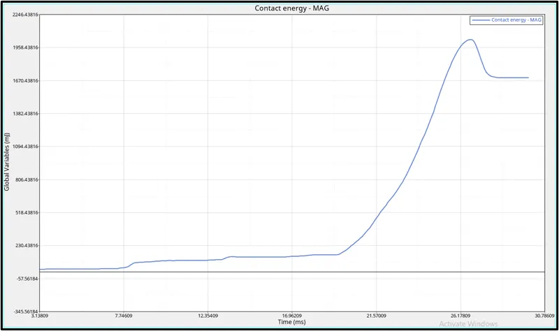
Contact energy is the energy acting opposite to the system to prevent the penetration acting on the system. When the force is applied on the body, the crush tube starts to deform but the penetration happening is low in initial stage. The contact energy will be low until 20ms. Once the deformation is maximum, the elements will be forced to penetrate nut the opposite force which is contact energy will also increase which helps in the prevention of penetration. Once the defromation ends, the contact energy will become zero and will stay constant thereafter. To avoid this penetration, Gapmin value is set to 0.5.
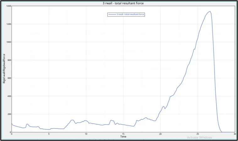
When the force with high velocity is acting on the crush tube, there will be slight change in shape which is called deformation. When the deformation is taking place there will also be a opposite force acting from the rigid wall . There comes time , when the deformation on the body will be very high and the opposite force coming from the rigid wall will also be high at 27ms. Once the deformation is maximum, the velocity will drop down to zero and in turn the Rigid body force also drops down to zero.
Max von Mises Stress: 7.345E-01 MPa
Max Internal Energy: 42273.2 kgmm2/ms2 at 26.8 ms
Max Contact Energy: 2029.46 kgmm2/ms2 at 26.7 ms
Rigid wall force : 1337.9 KN at 26.6 ms
Case 2 : Change the Inacti=6 and run.
Inacti is the Interfrence in type7 which helps to take the action if there is a initial penetration exists in the system.
Initial penetration is a term used frequently to describe the amount of penetration that exists between a node and its closest master segment (in the case of classic node/ segment treatment) or between two interacting segments (in the case of `segment-based` treatment) during the initialization of the problem.
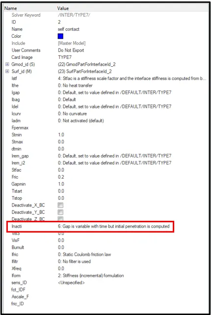
- Run the base simulation,by changing the value of inacti=6.
- From the subpanel below, click on Analysis > Select the save location > click Radioss.
- Simulation will start.
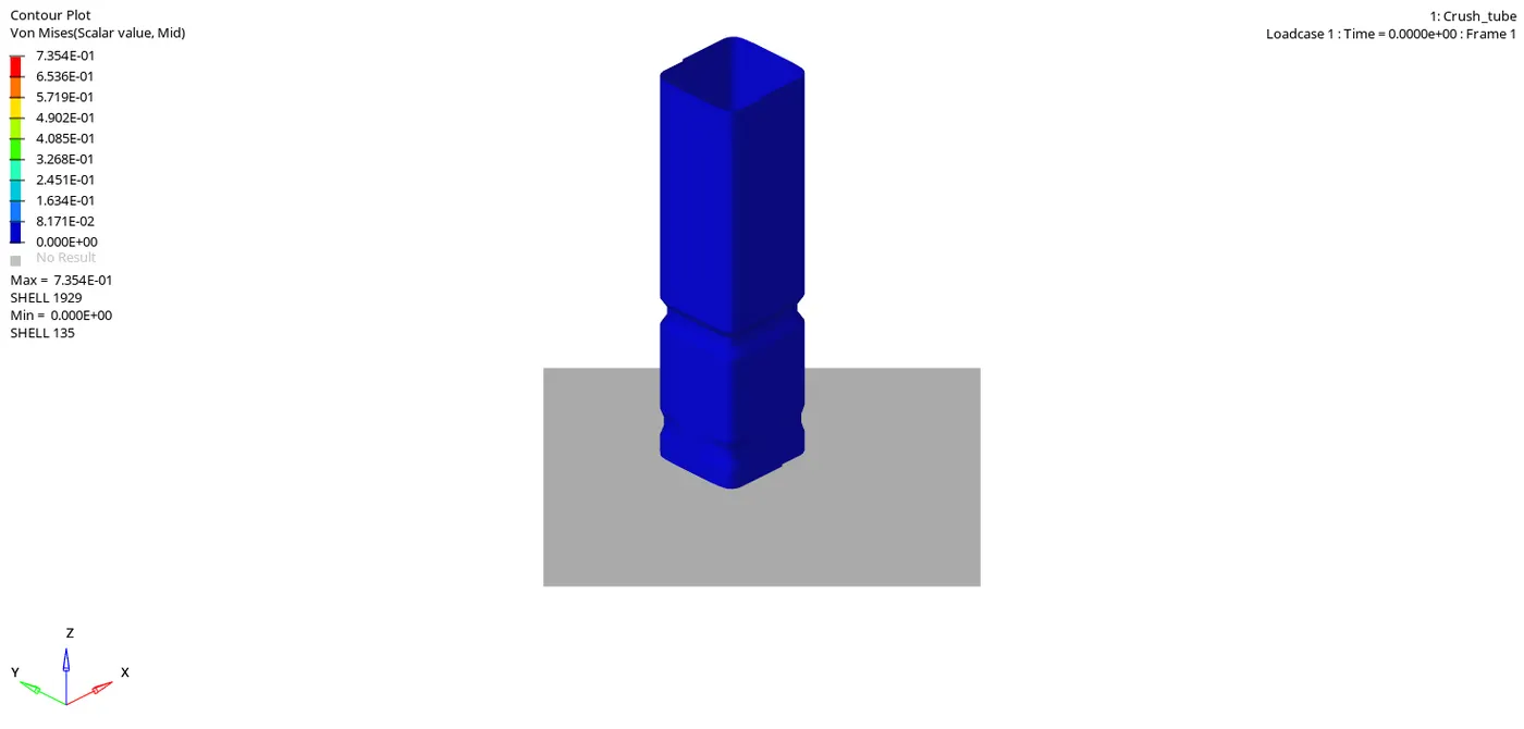
From the above simulation, the maximum stress acting was found to be 7.345E-01.
- At the end of the simulation, do the energy error and mass error checks and determine whether results would be acceptable
- Open the save location file and click on the output file of the simulation to check for the Energy error and Mass error.
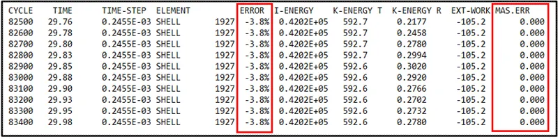
Maximum Energy error was found to be -3.8% and Maximum Mass error was found to be 0.
Plot the graph of rigid wall forces, internal energy, kinetic energy, contact energy of the simulations.
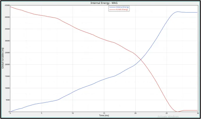
Initially, the kinetic energy will be high when the force is applied on the body. On the first impact, the crush tube starts to deform and the surrounding energy is stored in it. Because of this stored surrounding energy, the internal energy starts to increase. The kinetic energy decreases when the impact happens and the absorbed energy increases which inturn increases the internal energy. During maximum deformation, ther velocity will become zero and the kinetic energy will also dip down to zero. Due to this drop down in kinetic energy there will no ebergy to absorb for the crush tube which forces the internal energy to be contant thereafter.
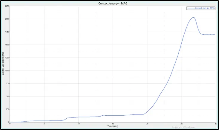
Contact energy is the energy acting opposite to the system to prevent the penetration acting on the system. When the force is applied on the body, the crush tube starts to deform but the penetration happening is low in initial stage. The contact energy will be low until 20ms. Once the deformation is maximum, the elements will be forced to penetrate nut the opposite force which is contact energy will also increase which helps in the prevention of penetration. Once the defromation ends, the contact energy will become zero and will stay constant thereafter. To avoid this penetration, Gapmin value is set to 0.5.
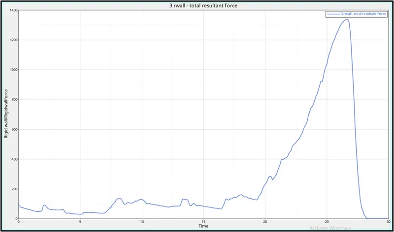
When the force with high velocity is acting on the crush tube, there will be slight change in shape which is called deformation. When the deformation is taking place there will also be a opposite force acting from the rigid wall . There comes time , when the deformation on the body will be very high and the opposite force coming from the rigid wall will also be high at 27ms. Once the deformation is maximum, the velocity will drop down to zero and in turn the Rigid body force also drops down to zero.
This case is similiar to case 2 as there was no initial penetration found in the model.
Max von Mises Stress: 7.345E-01 MPa
Max Internal Energy: 42273.2 kgmm2/ms2 at 26.8 ms
Max Contact Energy: 2029.46 kgmm2/ms2 at 26.7 ms
Rigid wall force : 1337.9 KN at 26.6 ms
Case 3 : Create the type 11 contact and run.
This interface simulates impact between edge to Edge or lines. A line can be a beam or truss element or a shell edge or spring elements.
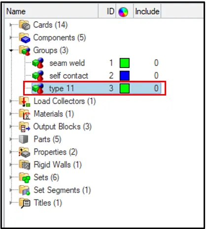
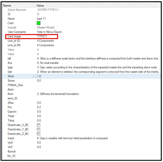
- Run the base simulation,by changing the card image to Type 11.
- From the subpanel below, click on Analysis > Select the save location > click Radioss.
- Simulation will start.
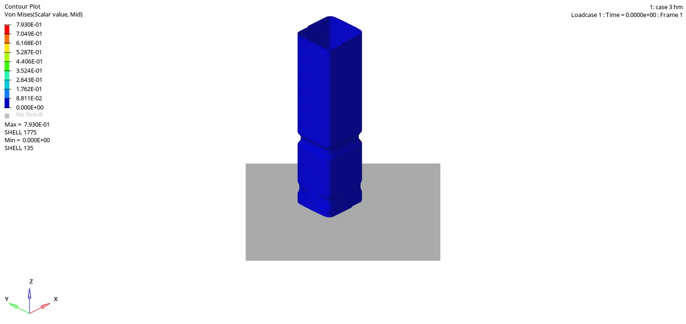
From the above simulation, the maximum stress acting was found to be 7.930E-01.
- At the end of the simulation, do the energy error and mass error checks and determine whether results would be acceptable
- Open the save location file and click on the output file of the simulation to check for the Energy error and Mass error.
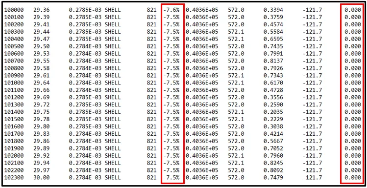
Maximum Energy error was found to be -7.5% and Maximum Mass error was found to be 0.
Plot the graph of rigid wall forces, internal energy, kinetic energy, contact energy of the simulations.
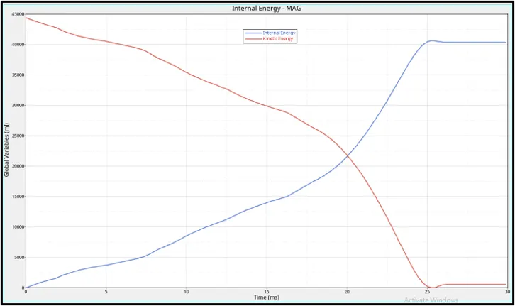
Initially, the kinetic energy will be high when the force is applied on the body. On the first impact, the crush tube starts to deform and the surrounding energy is stored in it. Because of this stored surrounding energy, the internal energy starts to increase. The kinetic energy decreases when the impact happens and the absorbed energy increases which inturn increases the internal energy. During maximum deformation, ther velocity will become zero and the kinetic energy will also dip down to zero. Due to this drop down in kinetic energy there will no ebergy to absorb for the crush tube which forces the internal energy to be contant thereafter. In this case , the card image used is type 11 and also the istf value is taken into consideration. The stiffness of the component is less and the time take for the maximum deformation is less when compared to case 1 and case 2. Hence force required for the maximum deformation to happen is also less.
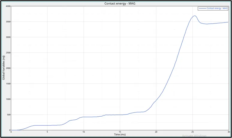
Contact energy is the energy acting opposite to the system to prevent the penetration acting on the system. When the force is applied on the body, the crush tube starts to deform but the penetration happening is low in initial stage. The contact energy will be low until 20ms. Once the deformation is maximum, the elements will be forced to penetrate nut the opposite force which is contact energy will also increase which helps in the prevention of penetration. Once the defromation ends, the contact energy will become zero and will stay constant thereafter. In this case, the value of istf is taken account. This means the stiffness of the material is less which causes larger deformation and hence the penetration of the elements increases accordingly. Therefore the contact energy increases with increase in penetration.
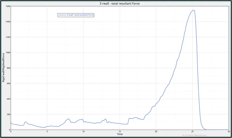
When the force with high velocity is acting on the crush tube, there will be slight change in shape which is called deformation. When the deformation is taking place there will also be a opposite force acting from the rigid wall . There comes time , when the deformation on the body will be very high and the opposite force coming from the rigid wall will also be high at 27ms. Once the deformation is maximum, the velocity will drop down to zero and in turn the Rigid body force also drops down to zero.We can say that , because of the consideration of istf the deformation in the crush tube is large and time taken for the maximum deformation is less compared to case 1 and case 2.
Max von Mises Stress: 7.930E-01 MPa
Max Internal Energy: 40625.6 kgmm2/ms2 at 25.3 ms
Max Contact Energy: 3693.04 kgmm2/ms2 at 25.3 ms
Rigid wall force : 1536.63 KN at 25.3 ms
Case 4 : Remove both notches and remove boundary condition on rigid body node then run.
- Import the model.
- Now, to remove the notch by using the align nodes option.
- Select the 1st two nodes for which the nodes has to be alligned and then select the nodes to be aligned.
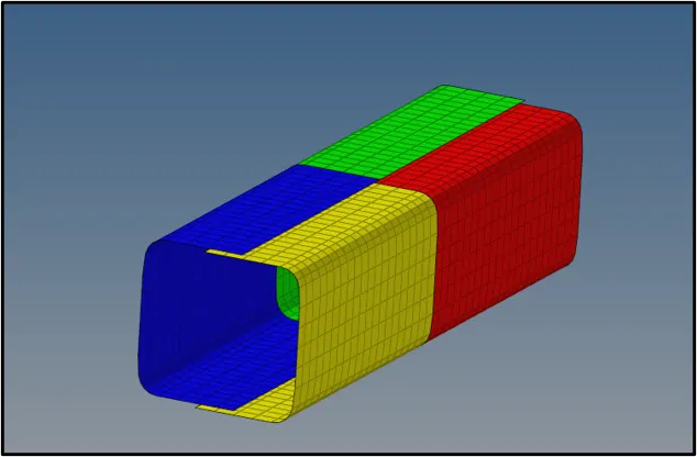
- The notch has been removed from the crash tube.
- Run the base simulation.
- From the subpanel below, click on Analysis > Select the save location > click Radioss.
- Simulation will start.
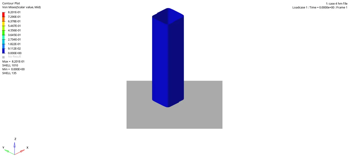
From the above simulation, the maximum stress acting was found to be 8.201E-01.
- At the end of the simulation, do the energy error and mass error checks and determine whether results would be acceptable
- Open the save location file and click on the output file of the simulation to check for the Energy error and Mass error.
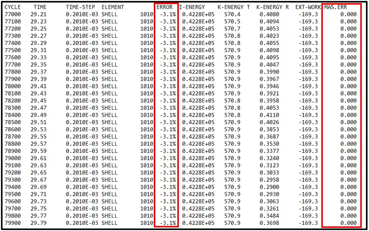
Maximum Energy error was found to be -3.1% and Maximum Mass error was found to be 0.
Plot the graph of rigid wall forces, internal energy, kinetic energy, contact energy of the simulations.
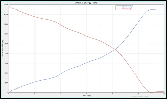
Initially, the kinetic energy will be high when the force is applied on the body. On the first impact, the crush tube starts to deform and the surrounding energy is stored in it. Because of this stored surrounding energy, the internal energy starts to increase. The kinetic energy decreases when the impact happens and the absorbed energy increases which inturn increases the internal energy. During maximum deformation, ther velocity will become zero and the kinetic energy will also dip down to zero. Due to this drop down in kinetic energy there will no ebergy to absorb for the crush tube which forces the internal energy to be contant thereafter. In this case the maximum internal energy which is comparatively higher than case 1. This is due to the removeal of the notch which has resulted in the increase in the stiffness of the material and hence the component has absorbed more force during deformation. If the notch was present the deformation would take less time to happen and also the stiffness of the material would be more.

Contact energy is the energy acting opposite to the system to prevent the penetration acting on the system. When the force is applied on the body, the crush tube starts to deform but the penetration happening is low in initial stage. The contact energy will be low. Once the deformation is maximum, the elements will be forced to penetrate nut the opposite force which is contact energy will also increase which helps in the prevention of penetration. Once the defromation ends, the contact energy will become zero and will stay constant thereafter. For this case the notch was removed which means more force is required for the deformation to happen and also the time taken for the deformation is more when comapred to case 1. It also concludes that the penetration taken place is less when compared to case 1.Hence to the contact energy incurred is less when compared to case 1.
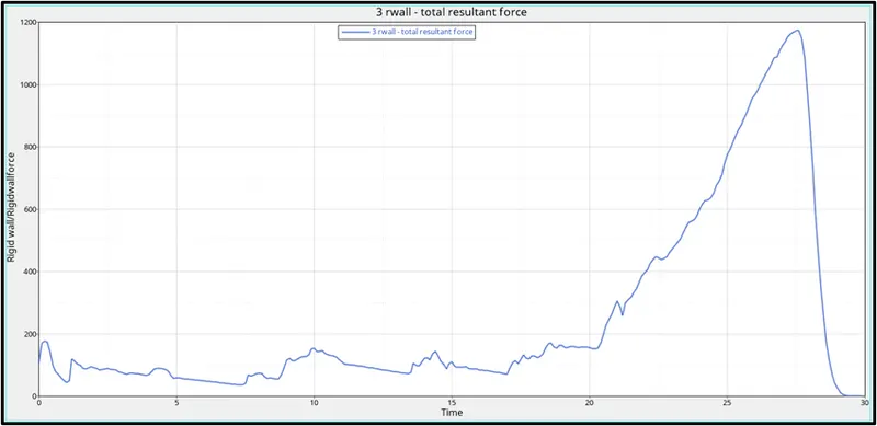
When the force with high velocity is acting on the crush tube, there will be slight change in shape which is called deformation. When the deformation is taking place there will also be a opposite force acting from the rigid wall . There comes time , when the deformation on the body will be very high and the opposite force coming from the rigid wall will also be high . Once the deformation is maximum, the velocity will drop down to zero and in turn the Rigid body force also drops down to zero. In this case the Rigid wall force is less comapred to previous cases.
Max von Mises Stress: 8.201E-01 MPa
Max Internal Energy: 42544 kgmm2/ms2 at 27.7 ms
Max Contact Energy: 4628.6 kgmm2/ms2 at 27.6 ms
Rigid wall force : 1173.82 KN at 27.3 ms
Case 5 : Create a new notch in the middle ,select the whole section and run.
- Import the model.
- Now create the notch in the middle by using trnaslate command
- select the nodes to translate
- Select the plane as reference on which direction the the nodes should translate
- Click on translate.
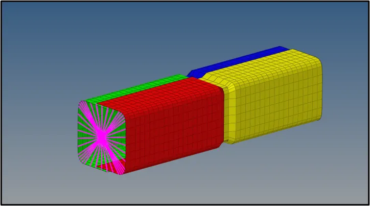
- The notch has been created in the crash tube.
- Run the base simulation.
- From the subpanel below, click on Analysis > Select the save location > click Radioss.
- Simulation will start.
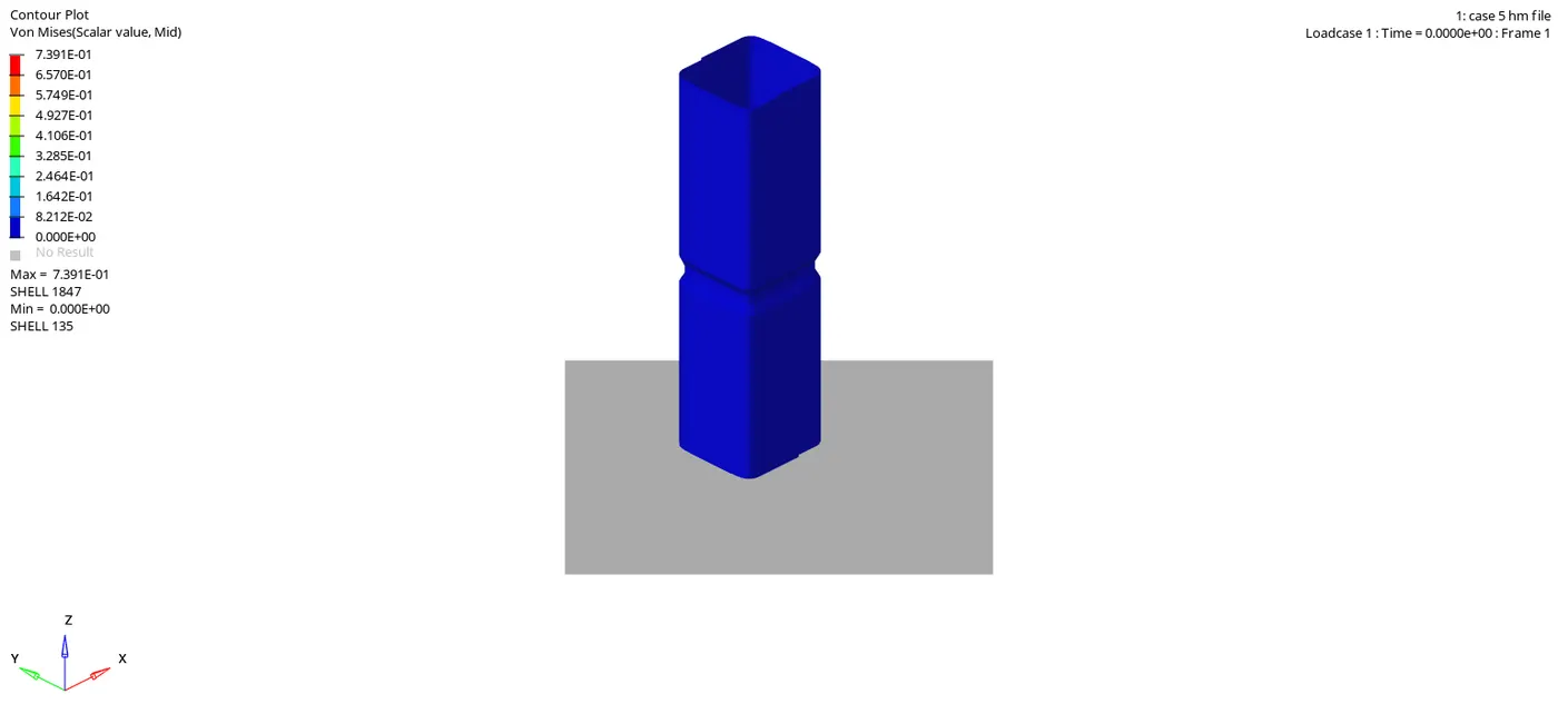
From the above simulation, the maximum stress acting was found to be 7.391E-01.
- At the end of the simulation, do the energy error and mass error checks and determine whether results would be acceptable
- Open the save location file and click on the output file of the simulation to check for the Energy error and Mass error.

Maximum Energy error was found to be -3.1% and Maximum Mass error was found to be 0.
Plot the graph of rigid wall forces, internal energy, kinetic energy, contact energy of the simulations.
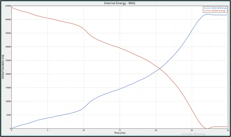
Initially, the kinetic energy will be high when the force is applied on the body. On the first impact, the crush tube starts to deform and the surrounding energy is stored in it. Because of this stored surrounding energy, the internal energy starts to increase. The kinetic energy decreases when the impact happens and the absorbed energy increases which inturn increases the internal energy. During maximum deformation, ther velocity will become zero and the kinetic energy will also dip down to zero. Due to this drop down in kinetic energy there will no ebergy to absorb for the crush tube which forces the internal energy to be contant thereafter. In this case the maximum internal energy which is comparatively lower than case 1. This is due to the removal of the notch which has resulted in increase of the stiffness of the material and hence the component has absorbed more force during deformation. If the notch was present the deformation would take less time to happen and also the stiffness of the material would be more. In this case the internal energy occured is comparatively lower in magnitude than case 1 as there was only one notch kept at the center whereas in case 1 there where 2 notches hence there was more force is absorbed by the system during the deformation.
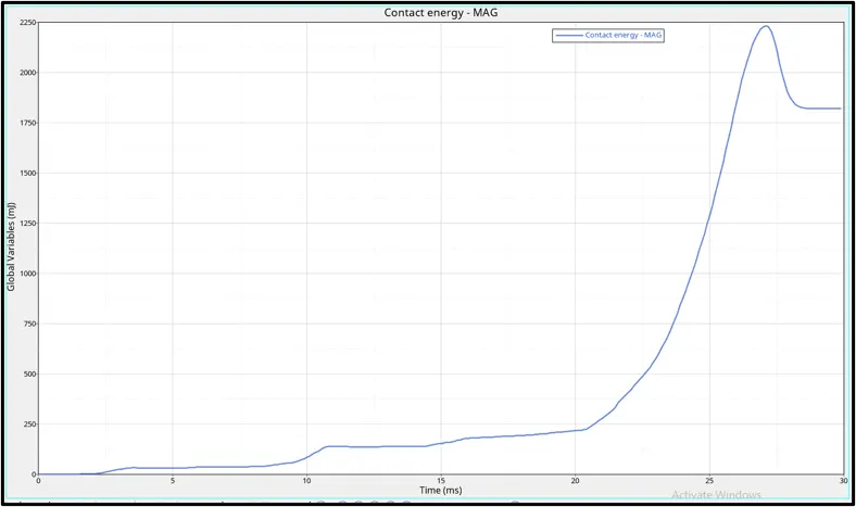
Contact energy is the energy acting opposite to the system to prevent the penetration acting on the system. When the force is applied on the body, the crush tube starts to deform but the penetration happening is low in initial stage. The contact energy will be low. Once the deformation is maximum, the elements will be forced to penetrate nut the opposite force which is contact energy will also increase which helps in the prevention of penetration. Once the defromation ends, the contact energy will become zero and will stay constant thereafter. In this case the contact energy incurred is more when compared to case 1 and case 2. This is due to only one notch at the centre which increases the rate of deformation, which inturn increases the rate of penetration.
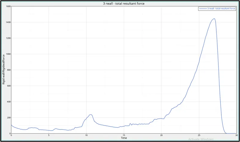
When the force with high velocity is acting on the crush tube, there will be slight change in shape which is called deformation. When the deformation is taking place there will also be a opposite force acting from the rigid wall . There comes time , when the deformation on the body will be very high and the opposite force coming from the rigid wall will also be high . Once the deformation is maximum, the velocity will drop down to zero and in turn the Rigid body force also drops down to zero.
Max von Mises Stress: 7.391E-01 MPa
Max Internal Energy: 41918.9 kgmm2/ms2 at 27.1 ms
Max Contact Energy: 2232.68 kgmm2/ms2 at 27.1 ms
Rigid wall force : 1444.99 KN at 26.8 ms
Case 6 : Create a new notch with nodes only from opposing 2 faces and run.
As explained in case 4 and case 5,create the notch only at the 2 faces of the tube as shown below.
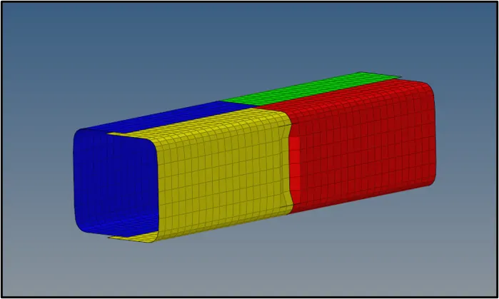
- The notch has been created at 2 opposite sides in the crash tube.
- Run the base simulation.
- From the subpanel below, click on Analysis > Select the save location > click Radioss.
- Simulation will start.
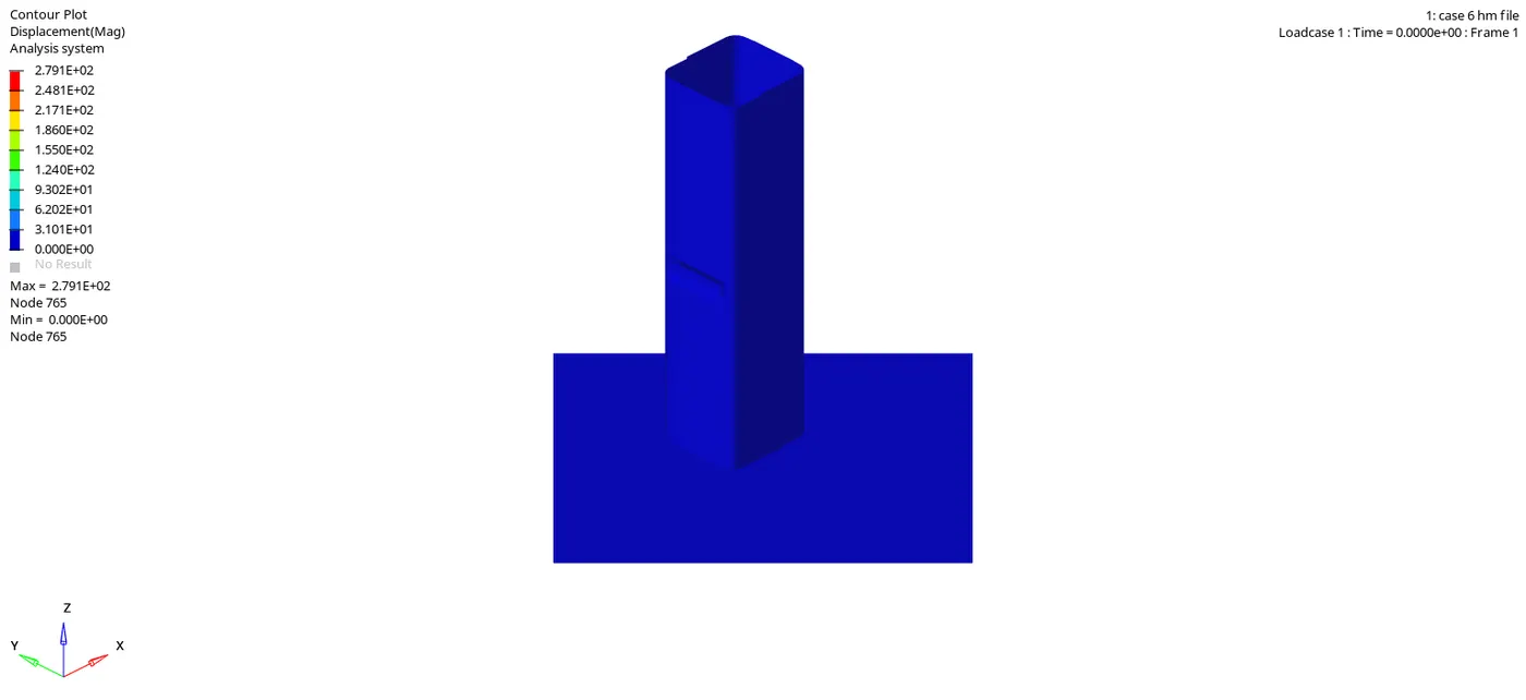
From the above simulation, the maximum stress acting was found to be 2.791E-01.
- At the end of the simulation, do the energy error and mass error checks and determine whether results would be acceptable
- Open the save location file and click on the output file of the simulation to check for the Energy error and Mass error.
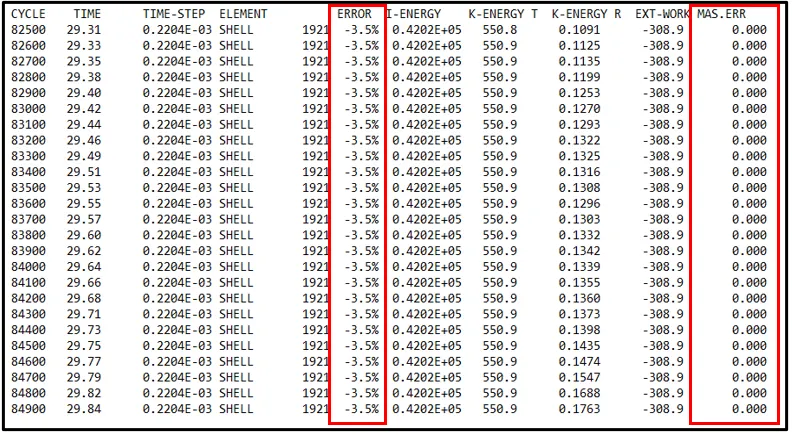
Maximum Energy error was found to be -3.5% and Maximum Mass error was found to be 0.
Plot the graph of rigid wall forces, internal energy, kinetic energy, contact energy of the simulations.
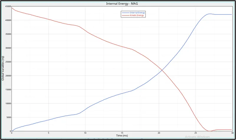
Initially, the kinetic energy will be high when the force is applied on the body. On the first impact, the crush tube starts to deform and the surrounding energy is stored in it. Because of this stored surrounding energy, the internal energy starts to increase. The kinetic energy decreases when the impact happens and the absorbed energy increases which inturn increases the internal energy. During maximum deformation, ther velocity will become zero and the kinetic energy will also dip down to zero. Due to this drop down in kinetic energy there will no energy to absorb for the crush tube which forces the internal energy to be contant thereafter. In this case we have kept notches only at the Opposite faces, hence the force required for the deformation to happen is high comparted to the previous case.Hence the internal energy incurred is more when compared to case 5.
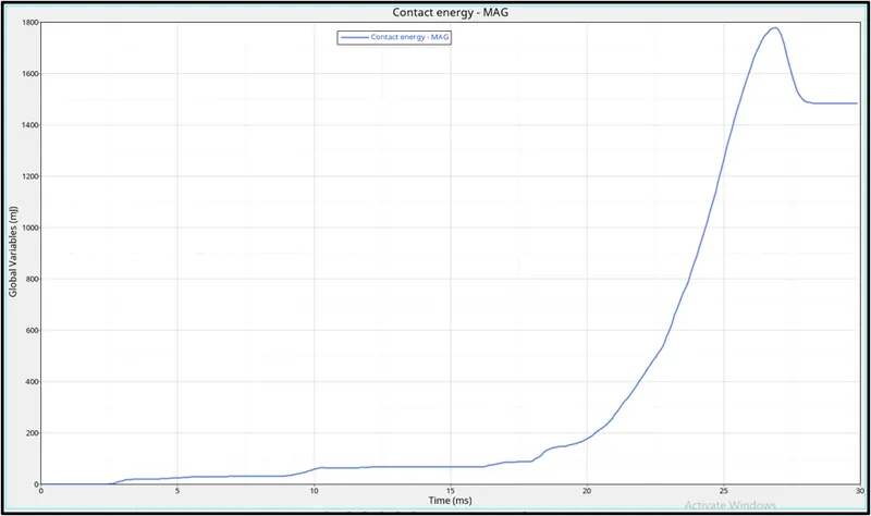
Contact energy is the energy acting opposite to the system to prevent the penetration acting on the system. When the force is applied on the body, the crush tube starts to deform but the penetration happening is low in initial stage. The contact energy will be low . Once the deformation is maximum, the elements will be forced to penetrate nut the opposite force which is contact energy will also increase which helps in the prevention of penetration. Once the deformation ends, the contact energy will become zero and will stay constant thereafter. In this case the contact energy occured is less due to the variation in the notch. Compared to the previous case the deformation is low and hence the amount of penetration is also less.
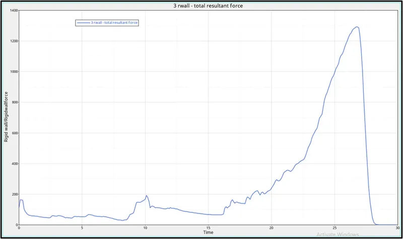
When the force with high velocity is acting on the crush tube, there will be slight change in shape which is called deformation. When the deformation is taking place there will also be a opposite force acting from the rigid wall . There comes time , when the deformation on the body will be very high and the opposite force coming from the rigid wall will also be high at 27ms. Once the deformation is maximum, the velocity will drop down to zero and in turn the Rigid body force also drops down to zero. The graph is similiar to the previous case but there is slight increase in the magnitude because of the number of the notch is 2, hence the force required required to deform the component is high when compared to the case 5.
Max von Mises Stress: 2.791E-01. MPa
Max Internal Energy: 42272.8 kgmm2/ms2 at 26.9 ms
Max Contact Energy: 1778.62 kgmm2/ms2 at 27.0 ms
Rigid wall force : 1292.73 KN at 26.8 ms
Conclusion :
All the required cases has been simulated with recommended data. From the above simulation, case 1 and case 2 are similiar. In case 3 the notch was removed and simualtion was ran, where the stiffness of the material is more and the amount of energy absorbed was comparitively less. In case 4,5 and 6 the notches were reworked which resulted in variation in internal energy.