Week 4- Challenge
Aim:
To develop a midsurface and to mesh the given model and to create 1D elements for the model with the given dimensions and Degree of freedom.
Given Data:
a. Rod element:- with only translational DOF and RBE2 link
Cross-Section: BOX- Dimension a= 12 mm
dimension b=10 mm
Thickness t= 0.75 mm
b. Beam element:- with all DOF and RBE3 link
Cross-Section: I Section- Dimension a= 8 mm
Dimension b= 10 mm
Dimension c= 8.5 mm
Thickness t1= 0.75 mm
Thickness t2= .6 mm
Thickness t3= .6 mm
c. Bar element:- with only x and y DOFs With RBE3 link
Cross-section: CROSS section- Dimension DIM1= 5 mm
Thickness DIM2= 1.2 mm
Dimension DIM3= 10 mm
Thickness DIM4= 1.2mm
d. & e. apply the mass of magnitude 10 with RBE2 link
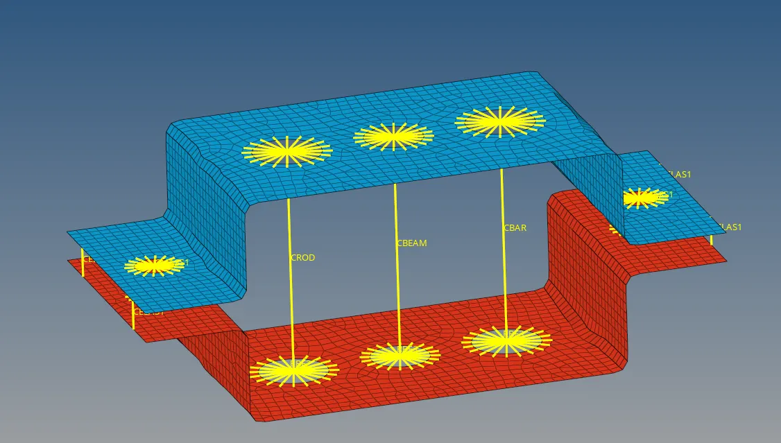
f. Join the two components with Spring elements
Procedure :
Step 1 :
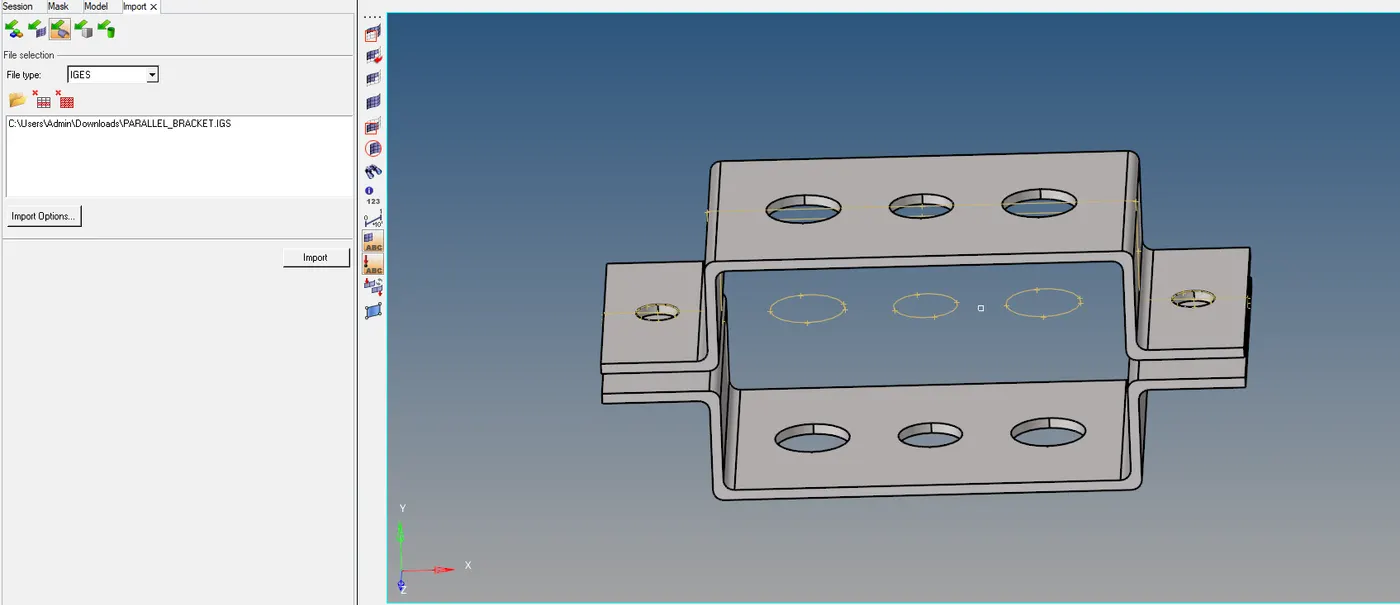
Import the given model into hypermesh using the import command.
Step 2 :
To inspect the given model and to Auto Cleanup :
Use the autocleanup tool to clear the geometrical errors from the model and make it error free.
Cleanup operations include the equivalencing of "red" free edges, fixing of small surfaces (relative to the element size), and detection of features such as beads. It also performs specified surface editing/defeaturing operations like the removal of pinholes (less than specified size), removal of edge fillets, and the addition of a layer of washer elements around holes.The Autocleanup panel performs the geometry cleanup portion of the BatchMesher and is available in interactive mode for ease of use. Since it performs a variety of geometry cleanup tools, the function will not be instantaneous and can take a few minutes depending on the size of the model. The criteria by which the cleanup functions is determined by the BatchMesher parameter and element quality criteria files, both of which can be edited from within this panel using the BatchMesher Parameter Editor.
GEOMETRY > AUTOCLEANUP > SURFACE > AUTOCLEANUP

Step 3:
Meshing the component :
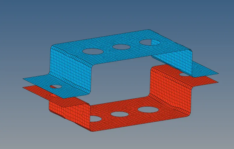
Use the Automesh option to generate a mesh of plate elements using surface geometry or existing shell elements to define the mesh area.
Set the options in the panel in any order that you feel comfortable using. Moving from subpanel to subpanel will not cause you to lose work. When you are finished making all your selections, click mesh to start the meshing process.
- Set the panel mode by selecting the appropriate subpanel.
- Select the meshing method by setting the entity selector to surfs or elems.
- Make the required element criteria settings.
- Set any algorithm options.
- Select the area to be meshed using the entity selector and any extended selection methods.
2D > AUTOMESH > SURFACE > MIXED/QUADS > ENTER ELEMENT SIZE > MESH

Step 4 :
To create 1D elements :
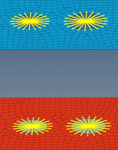
a. To create Rod elements with only translational DOF and RBE2 link :
- To create a rigid link.
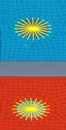
To create the rigid link that is the RBE2 connection click on the Rigids command in the subpanel. Select the required nodes for the which the connections has to be created.
A rigid element is an element created in a space between two nodes of a model where a rigid connection is desired. Rigid elements are element config 5 and are displayed as a line between two nodes with the letter R written at the centroid of the element. Rigid link elements are element config 55 and are displayed as lines between the independent node and the dependent node(s) with RL displayed at the independent node of the element. Rigid link elements can be created with dependent nodes attached to an element as a SET. If a rigid link with a dependent node set is deleted, the associated node set is also deleted. If the dependent node set in any panel is deleted, the connected rigid link element is also deleted. Dependent node sets are automatically created when rigid link elements are created. A node set created in the Sets panel can be connected as a set of dependent nodes to a rigid link element independent node.
1D > RIGIDS > CALCULATE NODES > MULTIPLE NODES > CHECK FOR DOFS > CREATE

- To create a rod element.
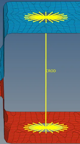
To create the rod element for the rigids link, select the rod command in the subpanel below.
A rod element is an element created in a space between two nodes of a model where rod properties are desired. The two nodes are related to each other based on the properties of the rod element connecting them. Rod elements have property pointers.
1D > ROD > SELECT NODES/LINKS > SELECT PROPERTY > SELECT ELEMENT TYPE (CROD)

b. To create Beam element with all DOF and RBE3 link :
- To create a rbe3 link
Similiar to the rigids, create a RBE3 link by selecting on the RBE3 command in the subpanel below.
RBE3's are interpolation constraint elements, where the motion of a dependent node is defined as the weighted average of the motions of a group of independent nodes. The dependent degrees of freedom and weighting factors can be specified or automatically calculated based on the geometry. RBE3 elements are element config 56 and are displayed as lines between the dependent node and the independent node(s) with RBE3 displayed at the dependent node of the element. RBE3's are typically used to distribute loads applied on the dependent node amongst the selected independent nodes.
1D > RBE3 > SELECT NODES > CREATE

- To create a beam element.
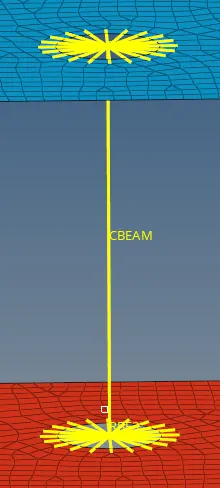
To create the beam element for the rigids link, select the rod command in the subpanel below.
The nodes are related to each other based on the properties of the bar or beam element connecting them. Properties associated with bar elements include vector orientation, offset vectors that end at A and B, or at A, B, and C, and pin flags to tell it what degree of freedom should carry through the beam.
1D > BAR > SELECT NODES > SELECT ORIENTATION > SELECT PROPERTY > SELECT ELEMENT TYPE (CBEAM)

c. To create Bar element with only x and y DOFs with RBE3 link
- To create a rbe3 link
Create a RBE3 link by selecting on the RBE3 command in the subpanel below.

1D > RBE3 > SELECT NODES > CREATE
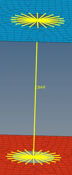
- To create a bar element.
To create the bar element for the rigids link, select the bar command in the subpanel below.
1D > BAR > SELECT NODES > SELECT ORIENTATION > SELECT PROPERTY > SELECT ELEMENT TYPE (CBAR)

d. To apply the mass of magnitude 10 with RBE2 link:
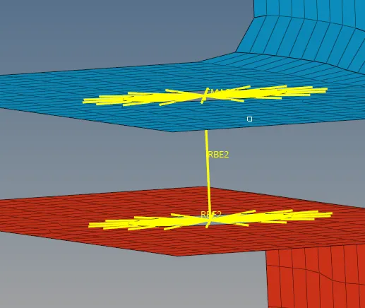
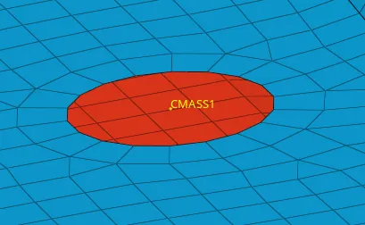
Now, apply mass to the rigids links created at two places. Click on the mass command in the below subpanel.
A mass element rests on a node and is used to represent mass. Mass elements are element config 1 and are displayed as a dot with the letter M written at the centroid of the element.
1D > MASS > SELECT NODES > ENTER MASS VALUE > ELEMENT TYPE (CMASS 1) > CREATE

f. To join the two components with Spring elements :
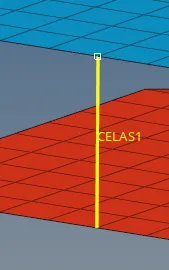
To join the top and bottom bracket, use the spring element command from the subpanel below.
A spring element is an element created in a space between two nodes of a model where a spring connection is desired. In Radioss, three noded or four noded springs can be created.Spring elements store a property and a degree of freedom (DOF).
1D > SPRING > SELECT NODES > CHECK FOR DOFS > CREATE

Step 5 :
To create cross sections for Rod, Beam and Bar :
To create the cross seections, use the Hyperbeam command from the subpanel below and create as per the given dimensions.
The HyperBeam panel is arranged into several subpanels. Each subpanel covers a different type of beam section, except for the more general edit section and section utils (utilities) subpanels. You can move freely between subpanels. Your work on one subpanel will not be lost if you switch to a different subpanel.
1D > HYPERBEAM > STANDARD SECTION > HYPERBEAM > SELECT STANDARD SECTION TYPE > CREATE
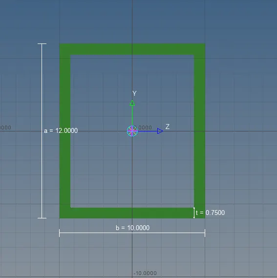
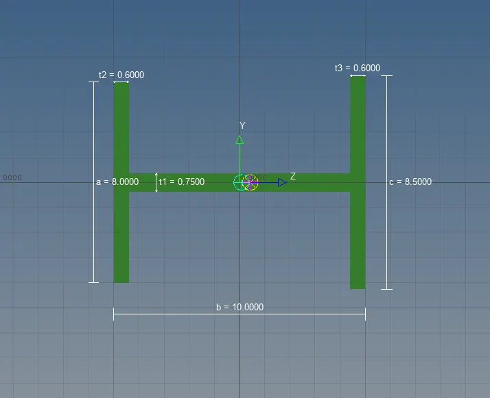
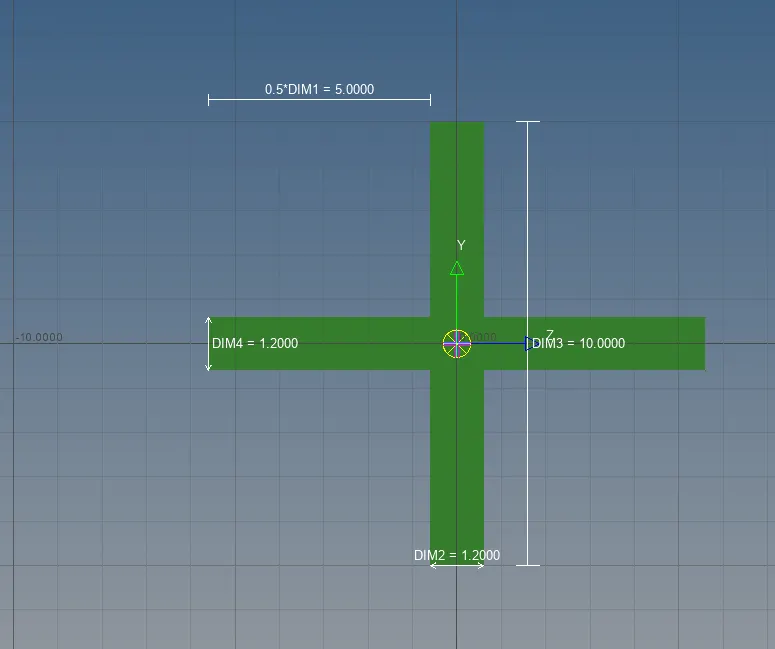
After finishing the cross section, add these cross sections to the individual properties and update these properties to the 1D elements tab.
Next change the view to 1d Element in detail representation.
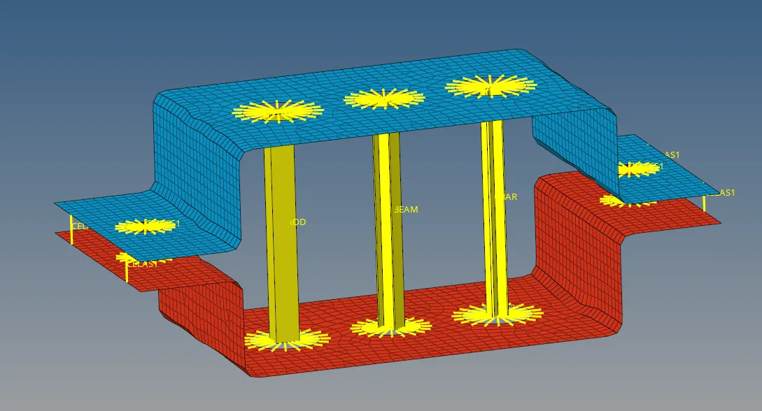
Result :
Thus, we came to know the concept of meshing, to create 1D elements and to create the cross sections for the 1D element.