Assignment 2
1. Check the material properties of the rail component and calculate the speed of sound in steel rail= STEEL
To check the material of the, firtsly the file needs to be imported.
- Import the starter file named, FIRST_RUN_0000.rad into Hypermesh.
- Click on the import solver deck option from the tab above and then click import.

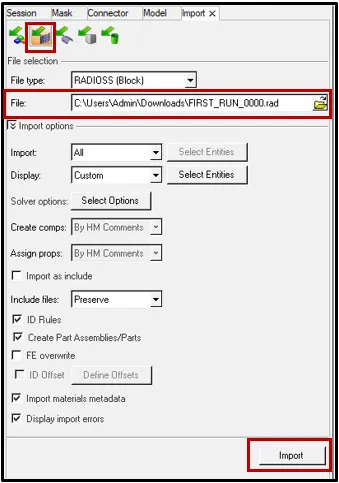
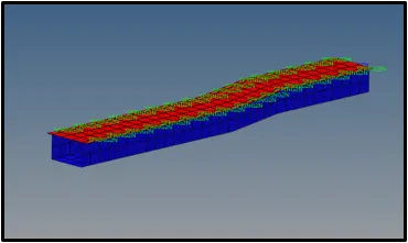
- The required model will be displayed on the hypermesh workbench.
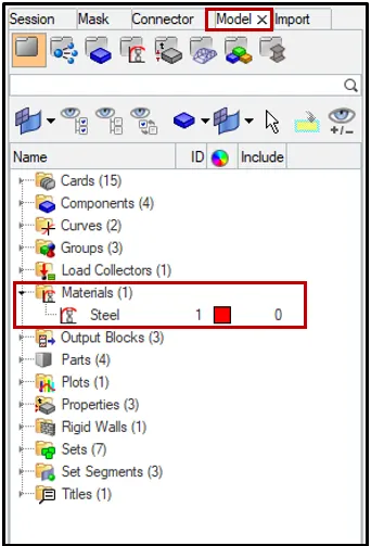
- Now, click on the model tab and click on the material.
- The material of the model can be seen, that is Steel.
 `sqrt(E/rho)`
2. The length of the rail is about 1000 mm.calculate the time takes for a shock wave to travel from one end of the rail to the other.
Speed of the Sound:
c=`sqrt(E/rho)`
where c=Speed of the Sound
E=Young's Modulous
rho=Density
`c=sqrt(210000/0.0078`
c= 5188.74 m/s
3.Time for sound to travel length of rail=______
`Delta t=l/c`
where t=Time
l=Length of the Rail
c=Speed of the Sound in Rail
`Delta t=1000/5188.74`
`Delta t=0.1927ms`
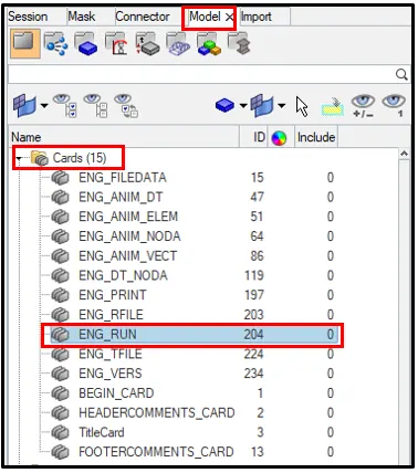
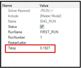
4.Edit the engine file so that the stress wave can be monitored, moving from one end of the rail to the other during impact -this will require a termination time equal to the time it takes for the sound to travel the length of the rail(set on/RUN card)
In the Model tab click on Cards > ENG_RUN > Change the T stop Value to 0.1927 as solved before.
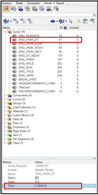
5.Set the frequency of animation output to a time that will give 20 animation steps(/ANIM/DT)
Click on ENG_ANIM_DT from the cards and set the Time Frequency value got from the solved equation as shown below.
To find the time frequency,we know that,
`T underset (fq)`=`frac{bb "Stop Time" underset(st)(T)}{bb "No of File Required (/ANIM/DT)"}`
`T underset (fq)`=`frac(0.1927)(20`
`T underset (fq)`=0.009635
Now, Enter this value in the `T underset (fq)` in ENG_ANIM_DT card.
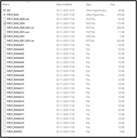
Now, go to subpanel below and click on Analysis and then click Radioss.
Select the input file location and then click radioss.
The simulation will be carried out.

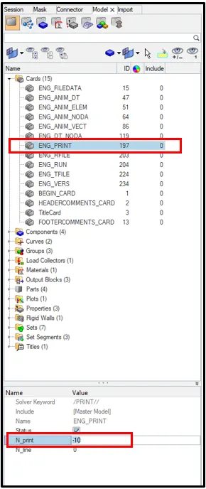
6.Change /print -10.
Click on the ENG_PRINT from the model cards and change the value of N_print to -10.
7. 3d meshing tetra mesh and hex mesh.
Volume mesh or "solid meshing" uses three-dimensional elements to represent fully 3D objects, such as solid parts or sheets of material that have enough thickness and surface variety that solid meshing makes more sense than 2D shell meshing.
Tetra mesh
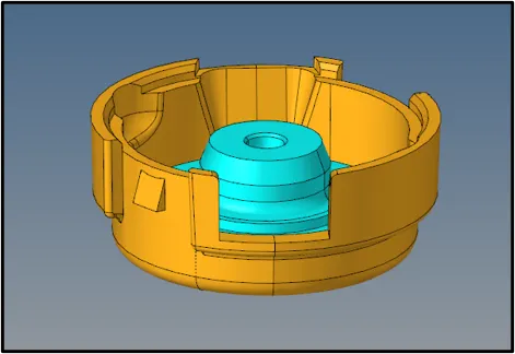
The below model can be meshed using the volume mesh option from the subpanel .
Step 1 :
Import the given model into hypermesh using the import command.
Step 2 :
Volume Meshing
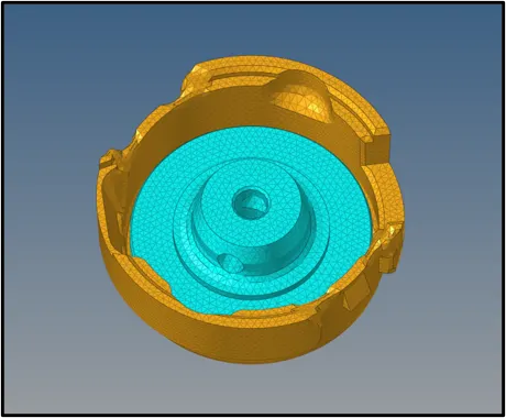
Now, start meshing using the volume mesh .
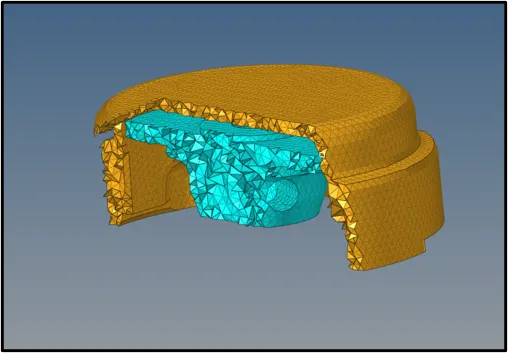
Use the Volume Tetra subpanel to generate a shell mesh and fill the enclosed volume with solid elements.Given a solid entity or a set of surfaces representing a closed volume, this meshing option generates a shell mesh and fills the enclosed volume with solid elements. You can choose to create a shell mesh (2D) using quads, trias, or mixed elements and a solid mesh (3D) using tetrahedral elements only or mixed (tetras and penta) elements. In addition, you can use proximity meshing, which refines the mesh in areas where the features are small and closer together.
Step 3 :
Check for tet collapse:
Tet Collapse are the Tetra elements whose collapse value falls below the value specified are highlighted when the tetra collapse function is selected. These elements remain highlighted until the Check Elems panel is exited.
Once the meshing, check for the Tet collapse for the valur of 0.15. The Tet collapse failure elements can be found out from the Check elements panel.
The total number of elements failing for tet collpase will be shown in status bar.


Hexa Mesh
Step 1 :
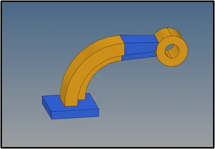
Import the given model into hypermesh using the import command.
Step 2:
- Mesh the base component using 2D meshing.
- Use the Automesh panel to generate a mesh of plate elements using surface geometry or existing shell elements to define the mesh area.
- Set the options in the panel in any order that you feel comfortable using. Moving from subpanel to subpanel will not cause you to lose work. When you are finished making all your selections, click mesh to start the meshing process.
- Set the panel mode by selecting the appropriate subpanel.
- Select the meshing method by setting the entity selector to surfs or elems.
- Make the required element criteria settings.
- Set any algorithm options.
- Select the area to be meshed using the entity selector and any extended selection methods.

Step 3 :
Creating 3D Meshing
- Use the Elem Offset panel to create and modify elements by offsetting from a mesh of plate or shell elements.

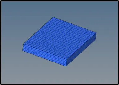
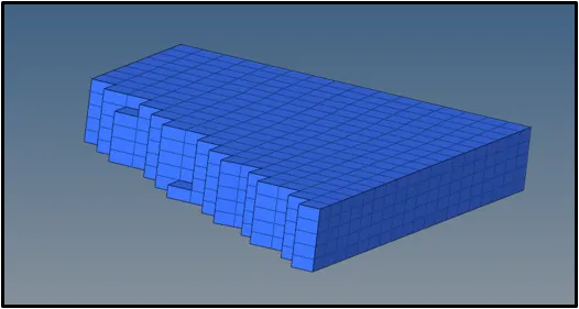
- 3D Mesh the Arm Curve using the Spin panel.
- Use the Spin panel to create a surface and/or mesh or elements by spinning a series of nodes, a line or lines, or a group of elements about a vector to create a circular structure.
- Use the Spin Geoms subpanel to create a surface and/or mesh or elements by spinning a series of nodes, a line, or lines about the normal of a user-defined plane.

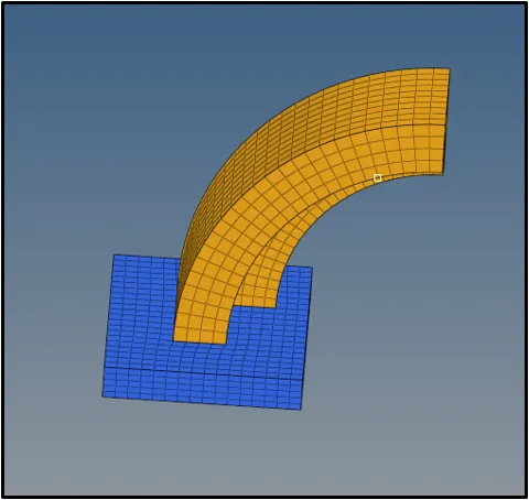
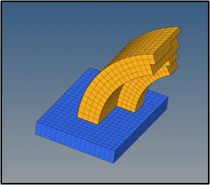
- 3D Mesh the Arm Straight using Linear solid panel.
- Use the Linear Solid panel to create solid elements between two groups of plate elements.
- Select the elements where you want the plot elements to begin.
- Define the from line's alignment by clicking N1 and selecting three alignment nodes on the first set of elements.
- Select the elements where you want the plot elements to end.
- Define the to line's alignment by clicking N1 and selecting three alignment nodes on the second set of elements.
- Specify the number of layers to be created between the two groups of elements.
- Click on Solids to Generate the solid elements.

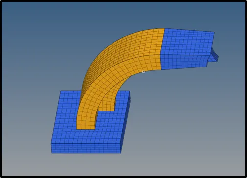
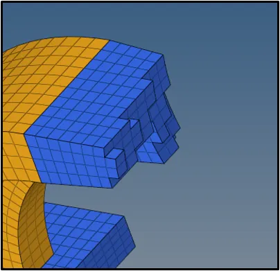
- 3D Mesh the Boss using Solid Map panel
- Firstly,mesh the boss top Surface with 2D Mesh.
- Use the Solid Map panel to create a mesh of solid elements in a solid geometric volume.
- Use the General subpanel to access all of the possible entry controls for maximum flexibility.
- Choose a method for selecting source geometry that defines the source face of the 3D volume.
- Select surfaces that define the source face of the volume/solid.
- Select the elements/mesh that correspond to the source face extruded to create the solid mesh. If the source face type chosen is a surface, the elements to drag selection is optional as the elements associated to the surface are automatically selected.
- Choose a method for selecting the geometry that defines the destination face of the 3D volume.
- Click on Mesh to generate the 3D Meshing

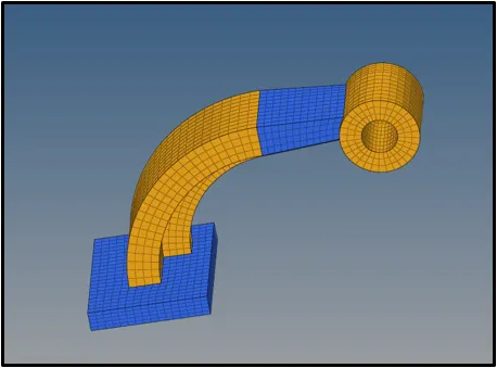
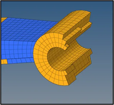
Result:
The starter file was imported and the speed of sound was calculated . The time taken for the sound to travel through rail was also calculated using basdic formulaes.
3D meshing and Hexa Meshing was also done on the given Model and was checked for Tet Collapse.