Week 6- Challenge
WEEK 6
Challenge Name: 2D Meshing of a Car Hood.
Aim:
To fix the Geometric Errors of the given model and to create the 2D meshing with proper mesh flow taking into account all the quality criteria provided.
Given Quality Criteria:
Target Element Length = 5mm
| S.N | Quality Criteria | Value |
| 1 | Aspect Ratio | 5 |
| 2 | Skewness | 45 |
| 3 | Warping | 15 |
| 4 | Taper | 0.5 |
| 5 | Min. Length | 2mm |
| 6 | Max. Length | 8mm |
| 7 | Min angle Quad | 45 |
| 8 | Max angle Quad | 135 |
| 9 | Min angle Tria | 20 |
| 10 | Max angle Tria | 120 |
| 10 | Tria % | 10 |
Steps:
- Import the Model into Hypermesh software.
- Extraction of Mid Surface
- Geometrical Clean up and Topology.
- Meshing
- Reflecting
Procedure:
Step 1 :
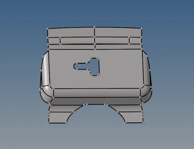
Import the given model into hypermesh using the import command.
IMPORT SOLVER DECK > IMPORT GEOMETRY > SELECT FILE TYTPE > IMPORT
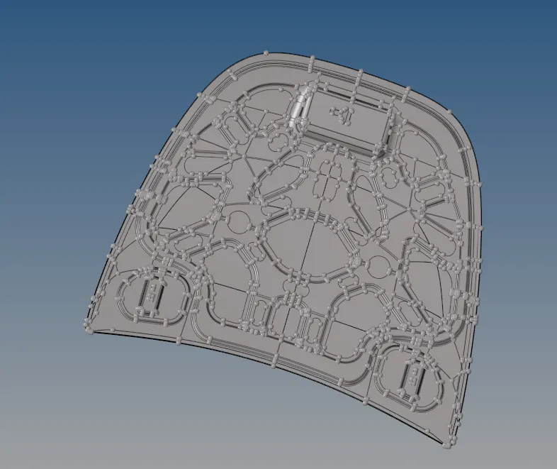
- Model has 4 different components names as below:
Upper Hood
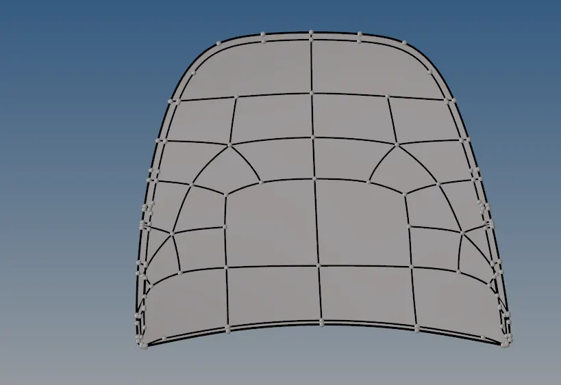
Lower Hood
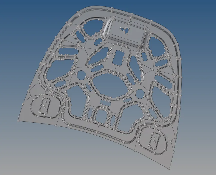
Side Latches
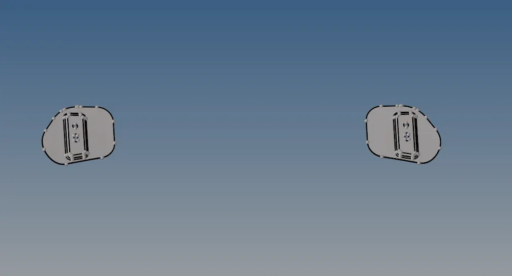
Center Latch
Step 2 :
Extraction of midsurface and Inspect :
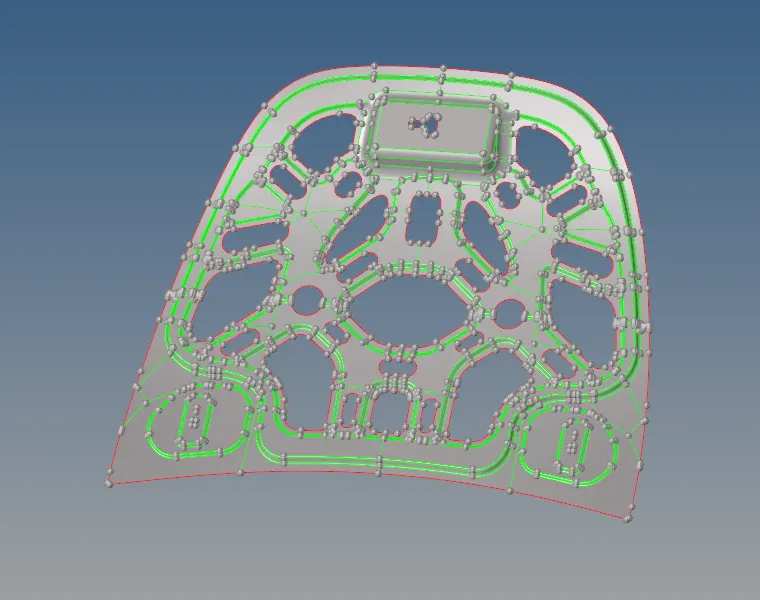
Use the Auto Midsurface tool to extract the midsurfaces for the given model. The Midsurface panel can be used to extract the midsurface of sheet metal stampings, molded plastic parts with ribs, and other parts that have thickness clearly smaller than width and length.
GEOMETRY > MIDSURFACE > AUTO EXTRACTION > SELECT SURFACE > EXTRACT

Step 3 :
Check for geometrical errors :
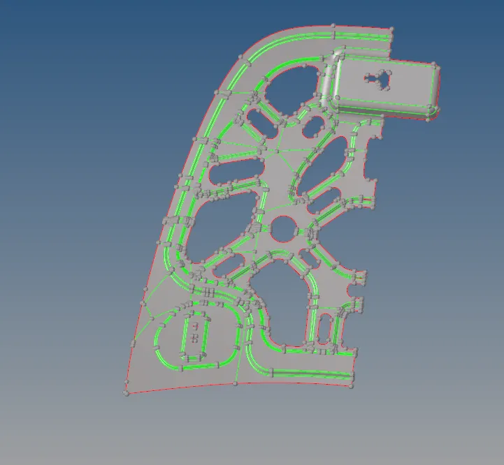
In this model, we can observe that the model in symmetry in either sides. Hence, we can delete one side of the surface. Use the Delete panel to delete data from a model database, preview and delete empty collectors, and preview and delete unused property collectors, material collectors, or curves. You can also delete an entire model database, if you wish to start with a clean database.

Now, check for the construction lines that might fail for quality errors and toggle the lines wherever neccessary.
Cleanup operations include the equivalencing of "red" free edges, fixing of small surfaces (relative to the element size), and detection of features such as beads. It also performs specified surface editing/defeaturing operations like the removal of pinholes (less than specified size), removal of edge fillets, and the addition of a layer of washer elements around holes.
The Quick Edit tools can be utilized with the option to force the immediate re-meshing of surfaces after a topology change (set in the Meshing Options panel accessible from the Preferences menu's, Meshing Options sub-menu; the setting is labeled topology revision on that panel.). Later, unwanted lines can be toggled using the toggle edge command.
Use the lines selector to select line(s).
- Left-click a free edge (red) to make it shared (green), or a shared edge to make it suppressed (blue).
- Right-click a suppressed edge to make it shared, or a shared edge to make it free.
In either case, the edge must meet the criteria for the type of edge you wish to change it to. For example, toggling a free edge to a shared edge requires the presence of a similar edge within the distance you specify in the tolerance field.
GEOMETRY > QUICK EDIT > TOGGLE EDGE > SELECT LINES
Check for unwanted lines and toggle it using the toggle edges option in the subpanel.
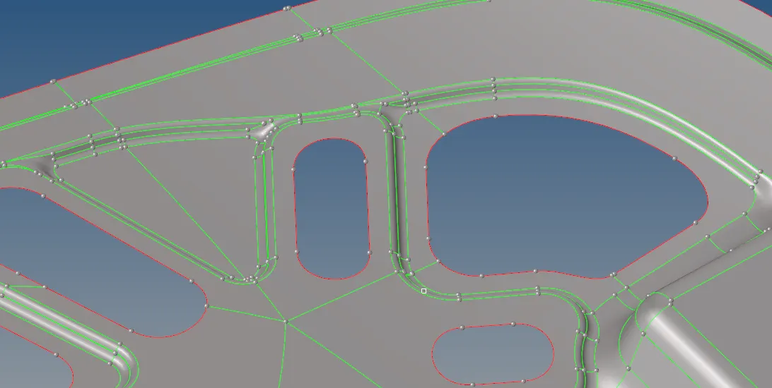 Before toggling
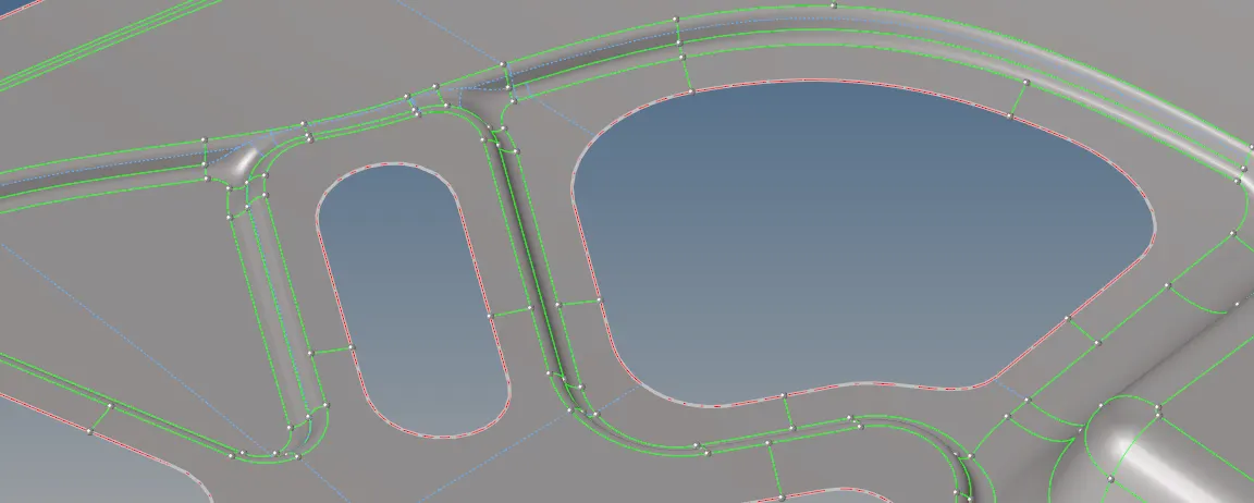 After toggling

Step 4:
Meshing the component :
Use the Automesh option to generate a mesh of plate elements using surface geometry or existing shell elements to define the mesh area.
Set the options in the panel in any order that you feel comfortable using. Moving from subpanel to subpanel will not cause you to lose work. When you are finished making all your selections, click mesh to start the meshing process.
- Set the panel mode by selecting the appropriate subpanel.
- Select the meshing method by setting the entity selector to surfs or elems.
- Make the required element criteria settings.
- Set any algorithm options.
- Select the area to be meshed using the entity selector and any extended selection methods.
2D > AUTOMESH > SURFACE > MIXED/QUADS > ENTER ELEMENT SIZE > MESH
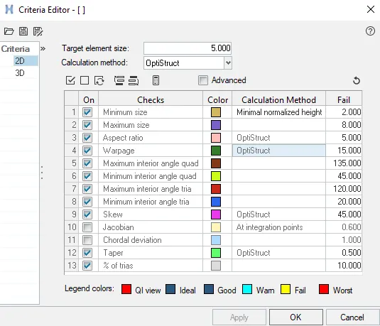 Required element criteria settings
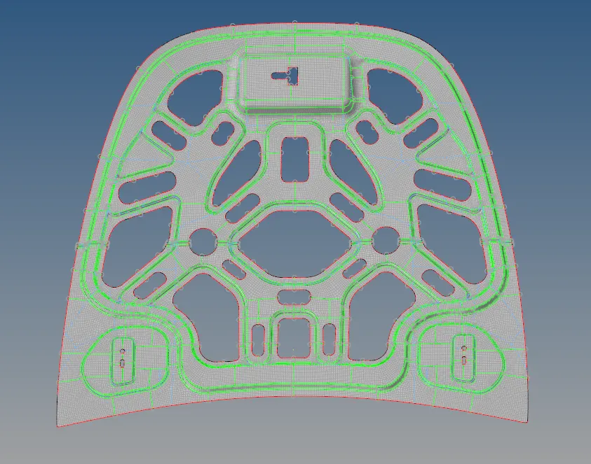
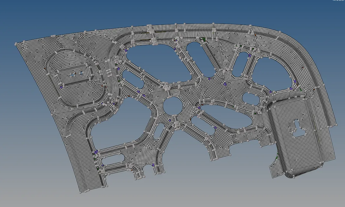 Meshed model
Step 5:
Checking for quality errors :
After meshing, lots of quality criteria occur. Clear the quality criterias using quality cleanup commands from the subpanel.
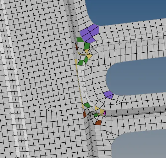
Use the Check Elems panel to verify the basic quality of your elements, as well as the geometric qualities of those elements.Each subpanel displays quality checks of a specific type, depending on dimensionality, time steps, and so forth. Each check is listed on a green command button; clicking the button performs a check and the results are summarized in the status bar.Criteria that you edit will be preserved even if you navigate to a different subpanel and then back again. However, criteria on different subpanels do not relate to each other, so changing the length requirement on the 1-d subpanel does not change the length requirement on the 2-d subpanel.Different checks are supplied to review the quality measurements of different types of elements. For example, if you have created a quad, it is possible that the quad has some degree of warpage. You can use the warpage function to check the element for warpage and to specify the maximum allowable warpage for that element.Another check available is for rigid loops. Use rigid loops to determine if a group of 1D rigid elements forms a loop. After it checks for instances where this has occurred, it highlights the elements that failed the test.
TOOLS > CHECK ELEMENTS > SELECT THE ELEMENT.

Criteria settings are stored and retrieved using a criteria file. You can save the results from the Quality Index (QI) panel to a summary file.

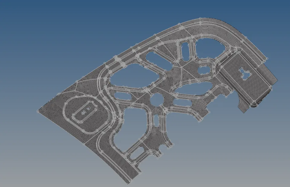 Quality cleared model
Step 6:
Reflecting to the other side :
Use the Reflect panel to reflect portions of a model about a plane, changing the selected portion into a mirror image of itself.
Undo a reflection by clicking reflect again without changing any other settings.Nodes located on the plane of reflection are not equivalenced. This function is available in the Edges panel.Loads, constraints, and systems attached to the reflected structure move to the new location of the parent entity, but they are not reflected.Local coordinate systems can be used to define the plane of reflection by using the vector option and selecting one of the vectors defining the local system.Reflecting surfaces separately from the nodes or elements built on them breaks association with those nodes/elements. Reflecting surfaces back to their original position will not restore these associations, but they can be restored via the Node Edit panel.When reflecting a component, all of the geometry (lines, surfaces, connectors, and points) and elements (nodes) contained in each component are reflected with the component, and associations are maintained.
TOOLS > RELECT > SURFACES/ ELEMENTS > SELECT AXIS > SELECT ELEMENTS/ SURFACES > DUPLICATE > CURRENT COMPONENT > REFLECT
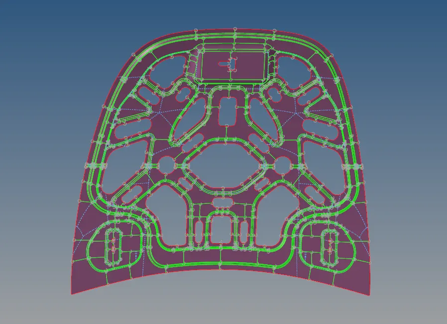
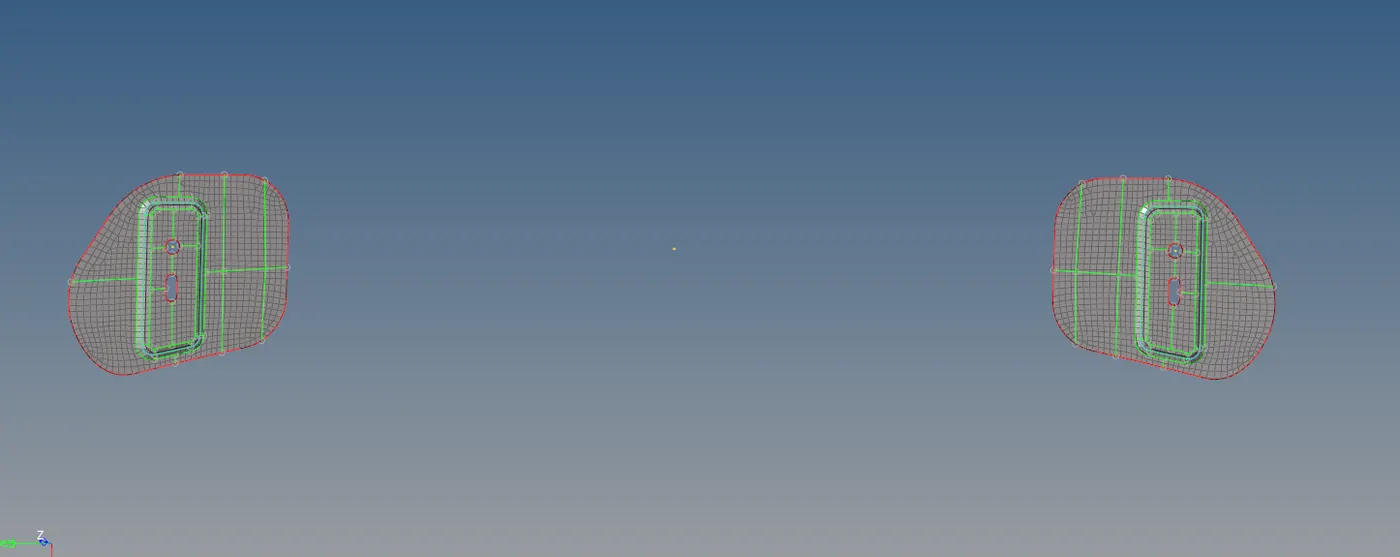
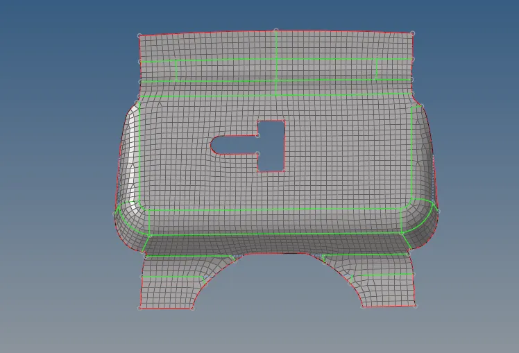
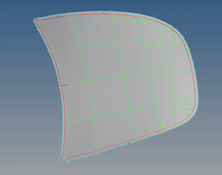
- The different meshed components are shown below.
Result :
Thus 2D mesh was created for the given hood component of a car according to the desired element quality criteria using Hypermesh.