Project 1
PROJECT 1 : PREPROCESSING OF IP SUBSTRATE
Aim:
To check for the geometrical errors and to extract the mid urace of the given component and to complete the 2D meshing for the component considering the given quality criteria.
Abstract:
What is FEA?
Finite element analysis (FEA) is a computerized method for predicting how a product reacts to real-world forces, vibration, heat, fluid flow, and other physical effects. Finite element analysis shows whether a product will break, wear out, or work the way it was designed.
Advantages of FEA :
- Enhanced design and early evaluation of critical design parameters.
- Virtual prototyping capability, meaning fewer physical prototypes are required and which are aligned to rapid prototyping.
- Efficient and less expensive design cycles.
- Increased productivity, and profit.
- De-risked design process.
- Reports can be produced as part of quality control and audit processes.
- Maximise performance through material selection and cost-efficiency.
- Reduced R&D and development costs.
- Certification or verification- The simulation data output is only as good as the input data. We have the engineering experience, expertise, and calibre to identify any potential anomalies. We will cross-check and carry out calculations to ensure the data output is correct.
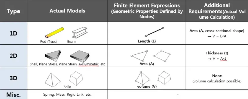
Types of Finite Elements:
- 1D Element
- 2D Element
- 3D Element
Instrumental Panels in Cars :
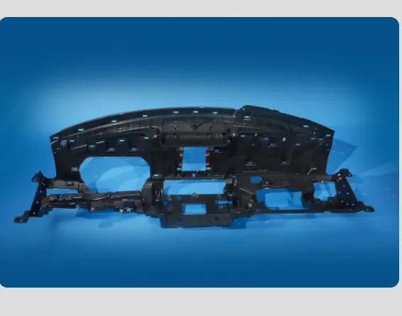
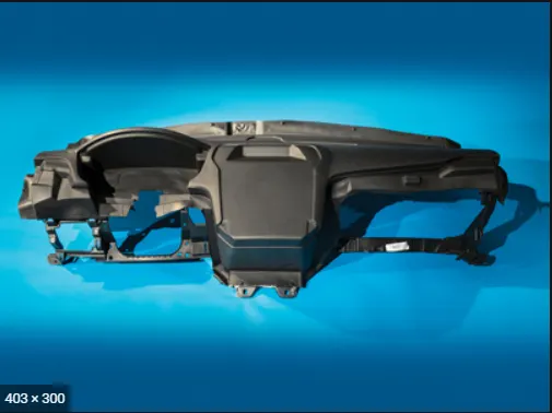
Instrument panels are often made of acrylonitrile-butadiene-styrene (ABS), ABS/polycarbonate alloys, polycarbonates, polypropylene, modified polyphenylene ether (PPE) and SMA (styrene-maleic anhydride) resins. These plastics allow for complex designs in items such as airbag housings, center stacks for instrument panels, and large, integrated instrument panel pieces.
Given Quality Criteria:
|
Sl No |
Quality Criteria |
Value |
|
1 |
Target Lenghth |
4 |
|
2 |
Minimum Length |
2 |
|
3 |
maximum Length |
6 |
|
4 |
Aspect Ratio |
3 |
|
5 |
Warpage |
15 |
|
6 |
Skewness |
45 |
|
7 |
Jacobian |
0.7 |
|
8 |
Minimum Quad Angle |
45 |
|
9 |
Maximum Quad Angle |
135 |
|
10 |
Minimum Tria Angle |
30 |
|
11 |
Maximum Tria Angle |
120 |
|
12 |
Tria Percentage |
15 |
Procedure :
- Importing the .IGS file of the IP substrate into ANSA.
- Geometry Clean up and Topology.
- Extraction of Mid Surface.
- Assigning the new Property ID .
- Defeaturing
- Meshing of the component.
STEP 1:
Importing the .IGS file of the IP substrate into ANSA.
- Import the IP substrate .IGS into ANSA as shown in fig 1.1
- Change the Mode to Topo and Entity
- Set the proper orientation as shown.
- Change the perimeter length to 1 as shown in fig 1.2.
MESH > PERIMETER > LENGTH
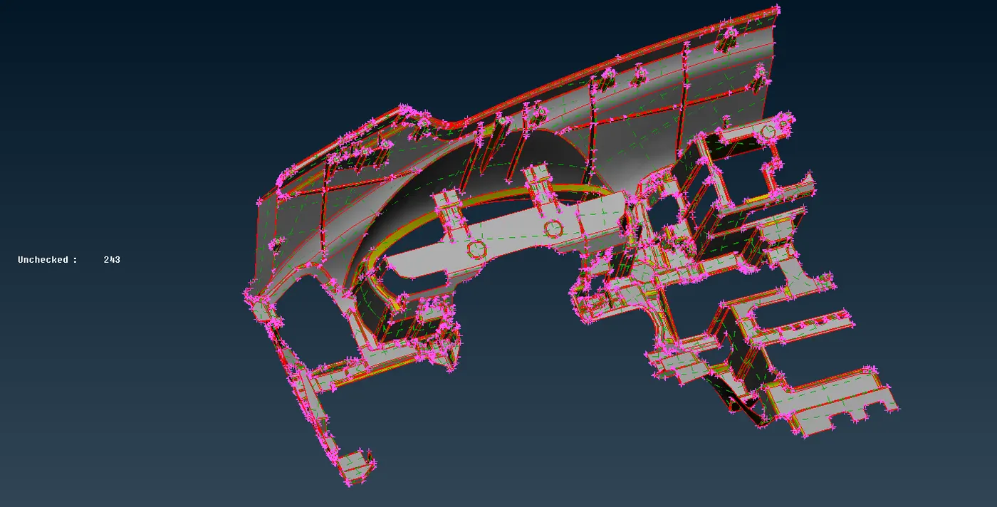 fig 1.1
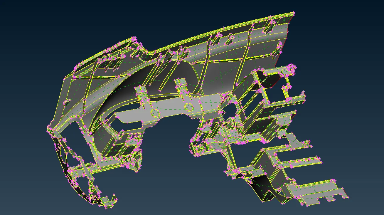 fig 1.2
STEP 2:
Geometry Clean up and Topology:
- Check for the geometry errors in the checks manager as shown in fig 2.1.
CHECKS > GEOMETRY > EXECUTE
- Eliminate all the Triple Cons and Cracks and make the component a error free model as shown in fig 2.2.
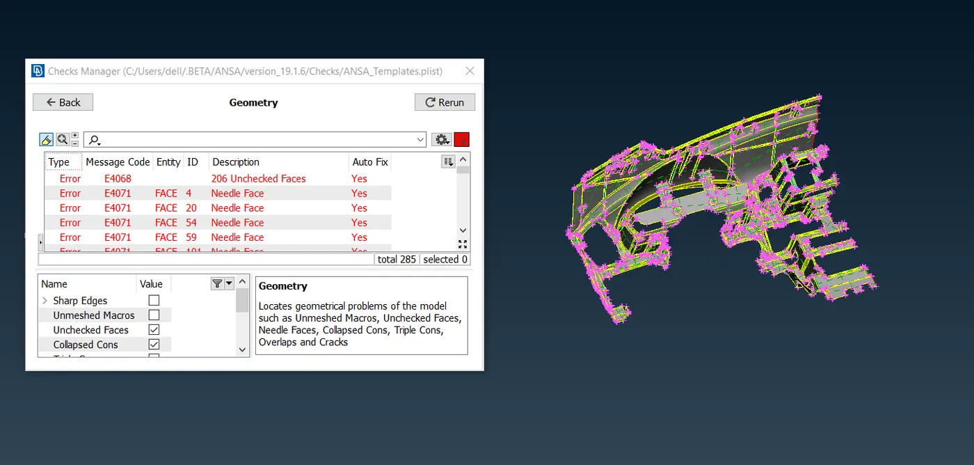 fig 2.1
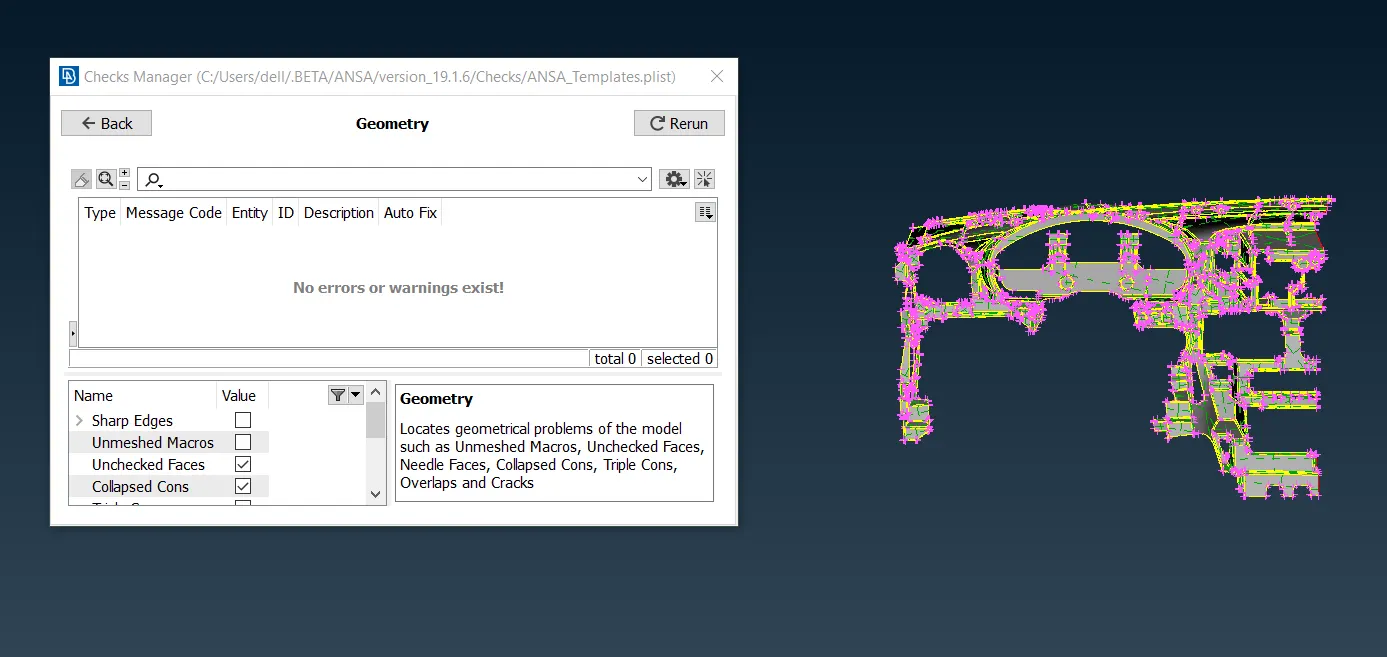 fig 2.2.
Step 3:
Extraction of Mid Surface
- Mid surface for the given component has to be taken manually as it is a plastic component and will be having varying thickness.
- Manual mid surface is taken by using Offset or Middle commands.
- In Offset command, the required faces for which the mid surface has to be captured must be selected and then enter the the offset value (thickness/2). Negative and positive signs indiactes the direction in which the value need to be offseted.
TOPO MODE > FACES > OFFSET
- In Middle command, two faces for te which the mid surface to be captured has to be selected and onc onfirmation the mid surface will be automatically generated.
TOPO MODE > FACES > MIDDLE
- In the given model, the main body has a thickness of 0.6mm and thus the mid surface can be taken by using the Offset command as shown in the fig 3.1 and 3.2.
- Mid surface of all the ribs are takrn by using Middle command as shown in fig 3.3.
- Mid surface of all the circular features or the fillets can be taken by using Curve Middle command.
TOPO MODE > CURVES > MIDDLE
- To cross check the mid surface by comparing with the parent geometry, enable PID Region and using INOT command hide the parent object. Thus, the midsurface of the component will be created.
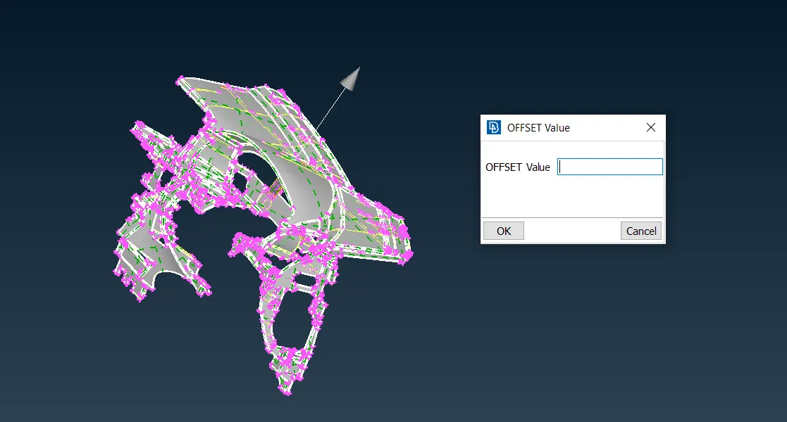 fig 3.1
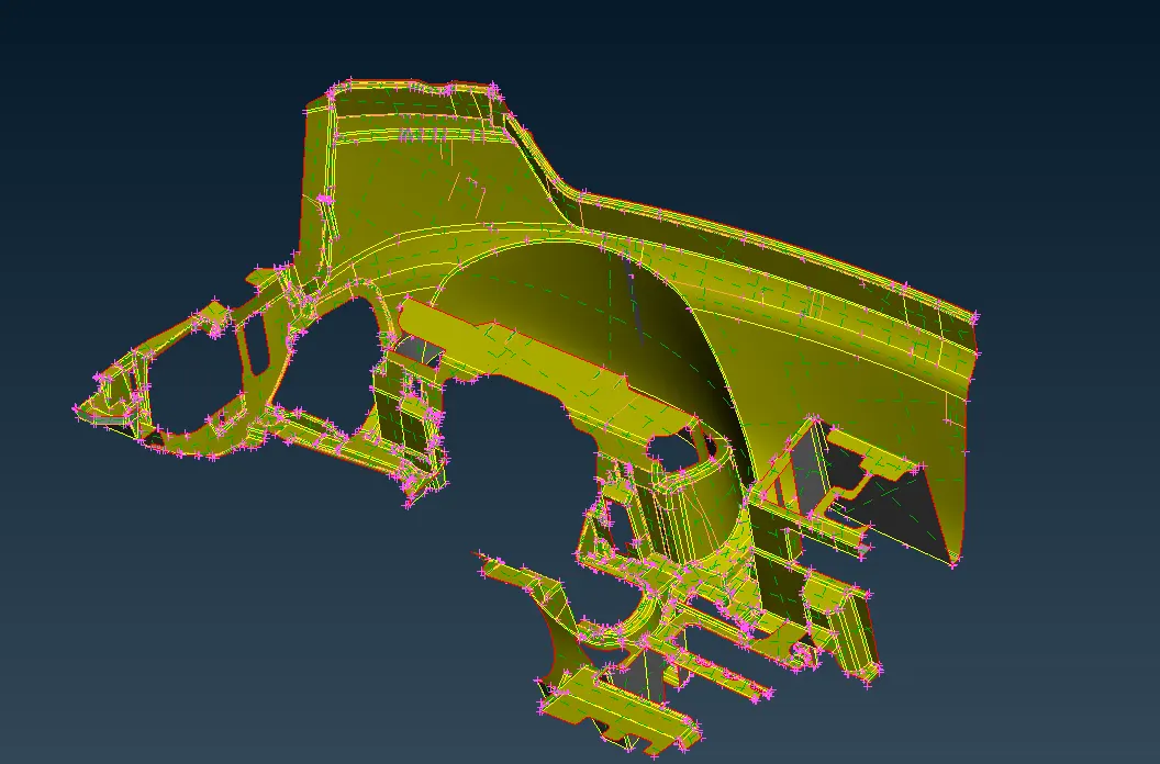 fig 3.2
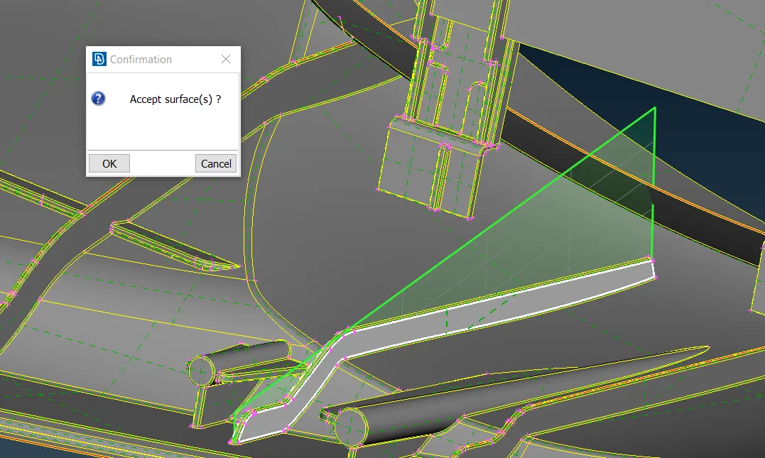 fig 3.3
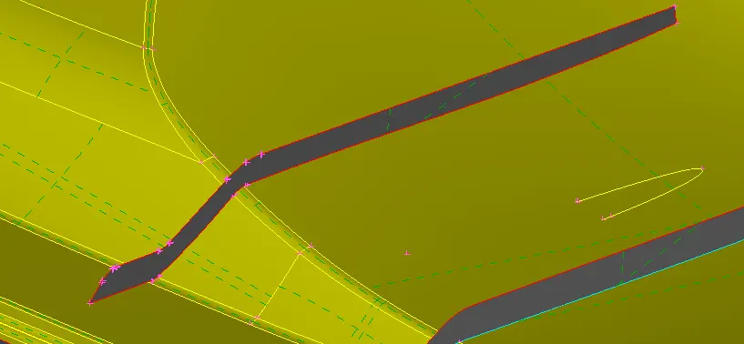 fig 3.4
- The ribs must be extended to the base surface using Extend command.
TOPO MODE > FACES > EXTEND
- Select the edge of the rib which is to be extended.
- On Center Mouse click, select the faces on which the ribs has to be extended.
- On Confirmation, the ribs will have been extended till the base surface as shown in fig 3.7 .
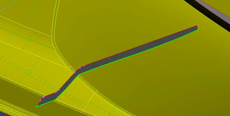 fig 3.5
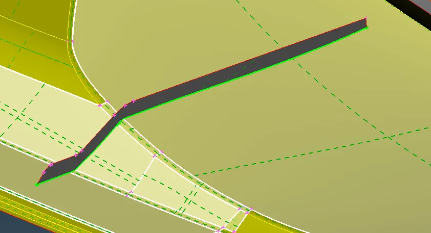 fig 3.6
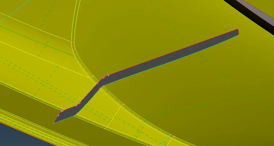 fig 3.7
- Fig 3.8 shows the overall mid surface of the component.
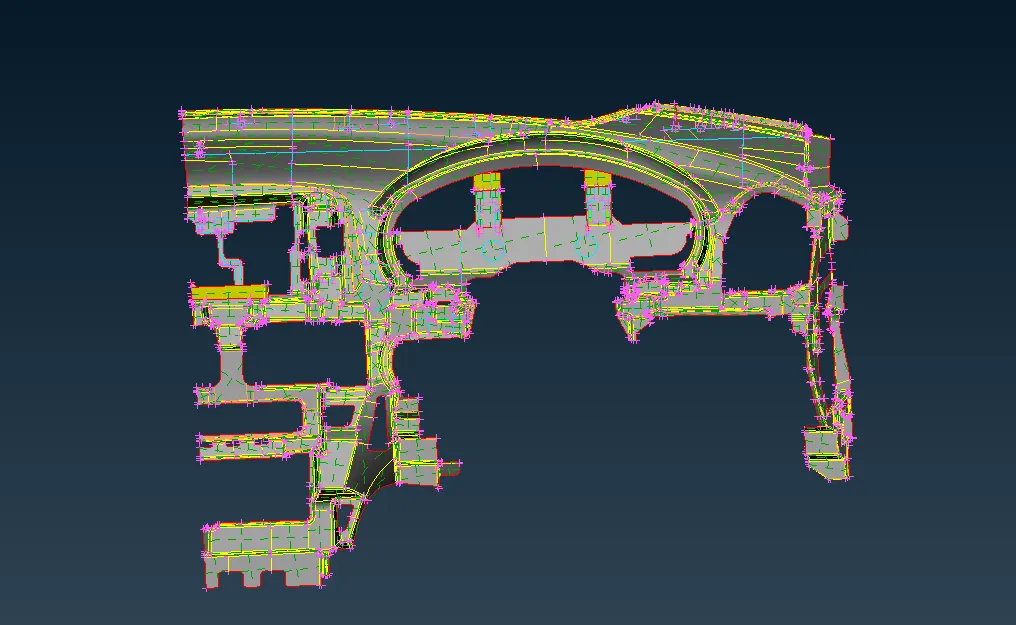 fig 3.8
Step 4:
Assigning New Property ID
- After the completion of extracting the mid surface, new property ID has to be assigned.
- Select the faces or the features for which the new PID has to be assinged and on confirmation the property tab will popup as shown in fig 4.1.
TOPO MODE > FACES > SET PID
- On Right Click, click on New > PSHELL, new property card will popup as shown in fig 4.2.
- Enter the required data and click OK .The new PID is created and thickness is assigned to the selected faces.
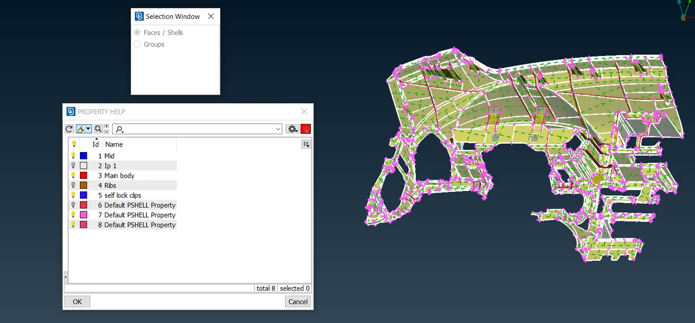 fig 4.1
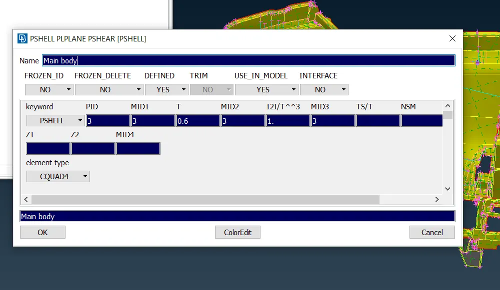 fig 4.2
Step 5 :
Defeaturing of the Component
- In some areas, the distance between the two cons or nodes are less than the minimum length and hence needed to be defeatured. These unwanted cons, edges or fillets can be eliminated using the Cut command.
TOPO MODE > FACES > CUT
- In Fillet areas defeature can be done using the Dach command as shown in fig 5.1, 5.2 and 5.3.
TOPO MODE > FACES > DACH
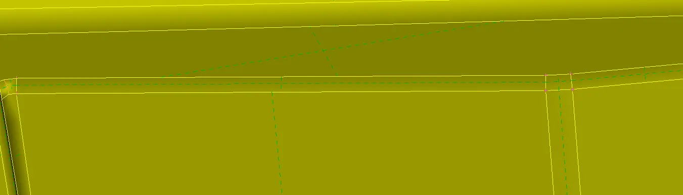 fig 5.1
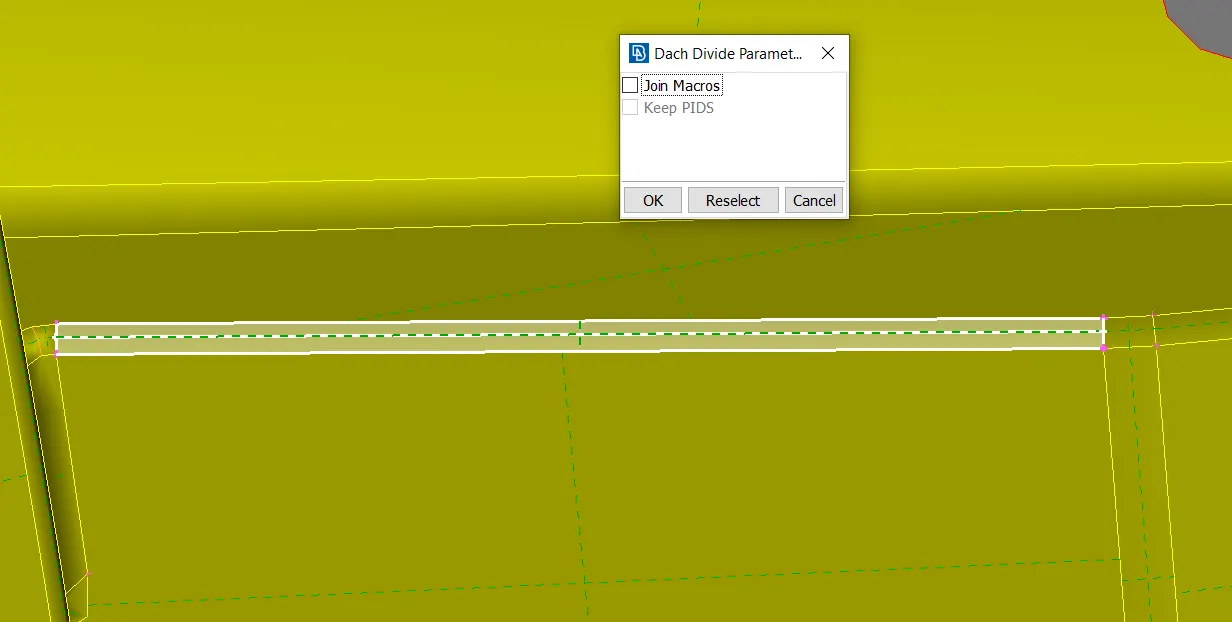 fig 5.2
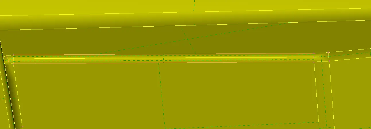 fig 5.3
Step 6 :
Meshing of the Component
- Go to Mesh mode from Topo Mode.
- Enter the required data of mesh parameters and quality criteria as shown in fig 6.1
UTILITIES > MESH PARAMETERS
UTILITIES > QUALITY CRITERIA
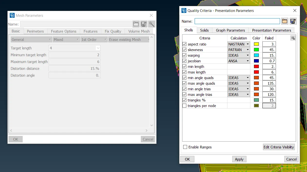 fig 6.1
- Change the value of permieter length to given target length.
MESH MODE > PERIMETER > LENGTH
- Now, mesh the given component.
MESH MODE > MESH GENERATION > BEST
- To improve the mesh flow or to modify the mesh flow use the Reconstruct command.
MESH MODE > SHELL MESH > RECONSTRUCT
- To smoothen the mesh flow use the Smooth command.
MESH MODE > SHELL MESH > SMOOTH
- To move the trias to the upward direction use Split command and to move the trias to the right or left use Swap command.
MESH MODE > ELEMENTS > SPLIT
MESH MODE > ELEMENTS > SWAP
- To move the trias to downwards use Paste command.
MESH MODE > GRIDS > PASTE
- Overall Component Meshing is shown in fig 6.2 and 6.3 .
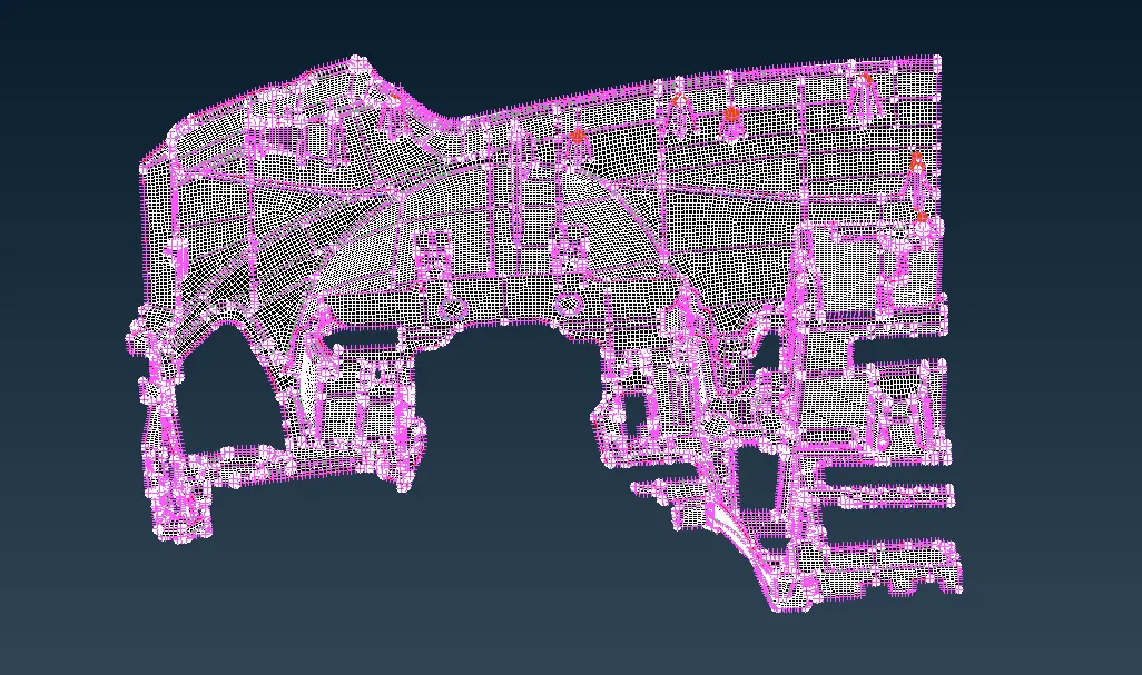 fig 6.2
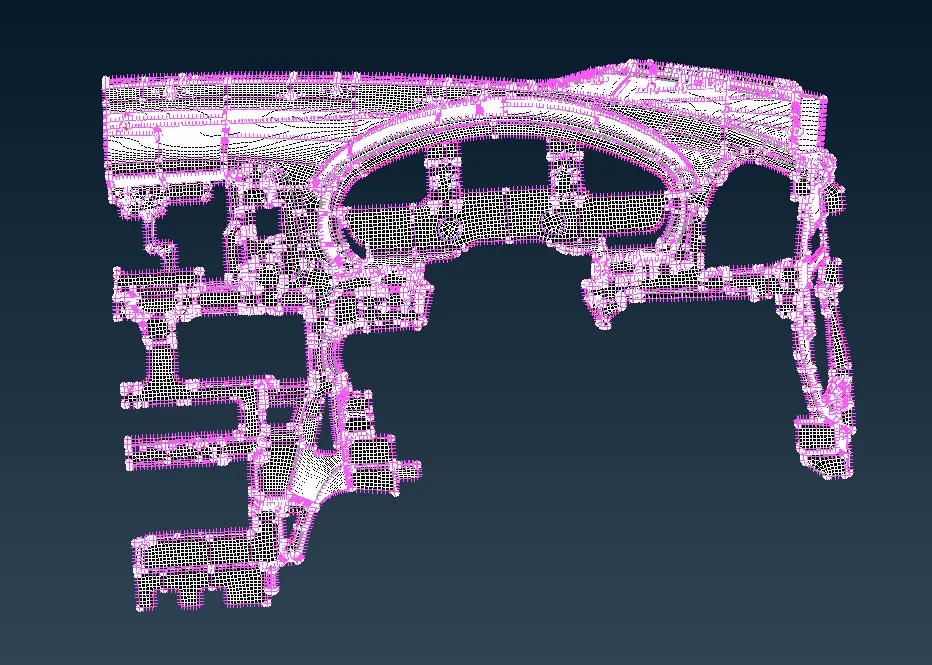 fig 6.3
- Finally, select the option Draw shell as solid in the presentation parameters as shown in fig 7.1 and 7.2 .
UTILITIES > QUALITY PARAMETERS > PRESENTATION PARAMETERS > DRAW SHELL AS SOLID
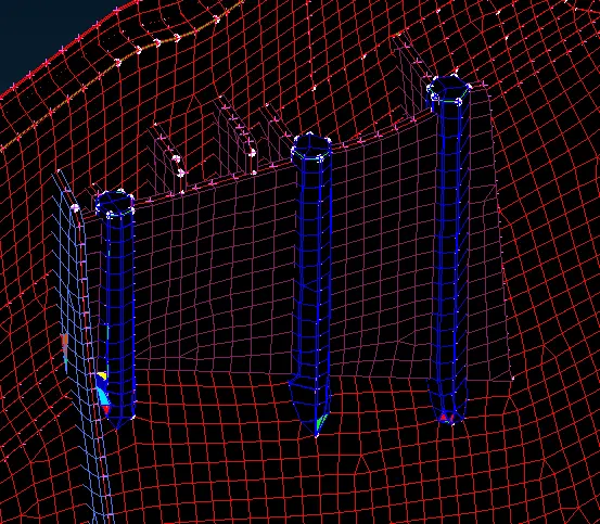 fig 7.1
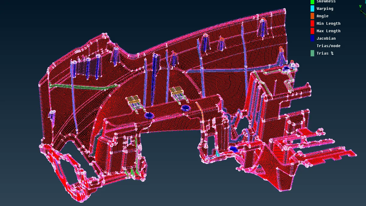 fig 7.2
Learning Outcomes:
- To fix Hepmetrical Errors and Geometric Cleanup of the component.
- To create and extract the mid surface of the given plastic Component.
- Defeaturing unwated cons, edges and fillets to create a better mesh flow.
- Meshing of the component considering all the given quality criteria.
- Removing opposite trias and rotating quads.
Conclusion:
- The given component is error free i.e the geometry is cleaned up.
- The midsurface is extracted for the the entire component.
- Thickness is appled for each and every feature and new property Id is allocated.
- Meshing is carried out for the entire component by sacrificing the qaulity criterias ar certain areas to retain it.
Google drive link :
https://drive.google.com/file/d/1EuZSlRiX-lAGrbfe-SjM0dCqPVRQlb87/view?usp=sharing