Assignment 1
Aim:
To check for the geometrical errors and to extract the midsurface of the given component and to complete the 2D meshing for the component considering the given quality criteria and to assign the thickness for the same.
Given Quality criteria :
- Target Element Length = 4mm
- Min. Length = 2mm
- Max. Length = 6mm
Approach for meshing :
- Spend sufficient time studying geometry.
- Check for symmetry.
- Geometry cleanup if necessary.
- Identify feasible splitting ways.
- Start meshing from critical areas.
- Split mesh strategy should be followed.
- Follow thumb rules during mesh.
- After meshing each area check connectivity between two meshes.
Procedure:
Step 1 :
Import the given model into hypermesh using the import command:
- Click on the import command on the tool bar.
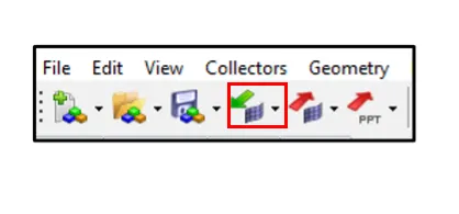
- Select the appropiate file type from the drop down menu (i.e STEP, IGES or HYPERMESH).
- Browse the file which is required to import.
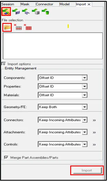
- Click import from the bottom and the required model will be displayed on the Hypermesh workbench.
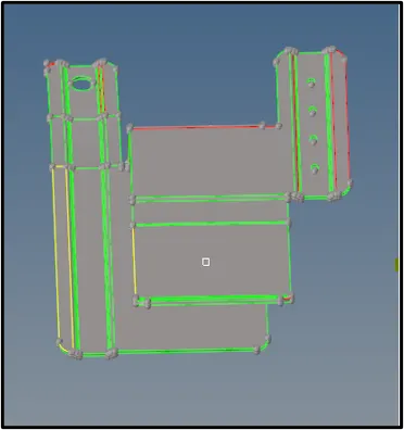 Model 1
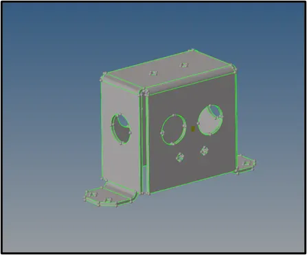 Model 2
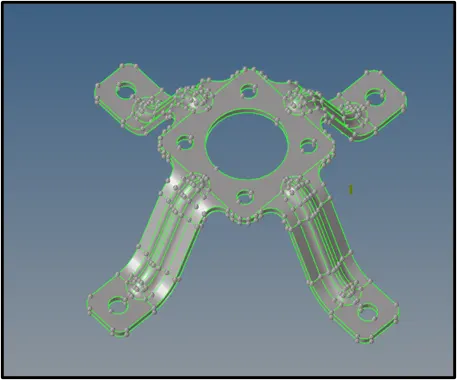 Model 3
Step 2:
Geometrical Cleanup and Topology of Parent model:
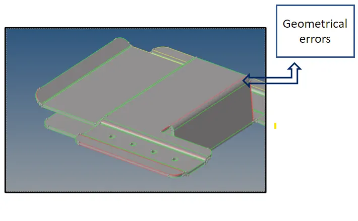
- Check for geomertrical errors in the parent model.
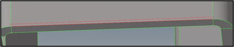
- Check for missing surfaces and free edges and fix it using the neccessary tools.
- Use the Quick Edit panel to split surfaces and washers, change the category (shared, free, and so on) of edges, create or delete surfaces and points, project points, and trim fillets.
- Check for the surfaces that might fail for minimum length and defeature if required using the defeature tool.
- Use the Edge Fillets subpanel to identify and remove edge fillets. Similar to surface fillets, edge fillets create smooth curves at the intersection of relatively perpendicular free edges. You can identify them based on the radius of the fillet arc, and then remove them.

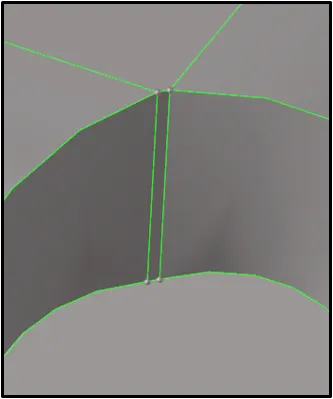
- Use the replace point option, to move points from their current locations to the locations of other points, effectively combining them.

Step 3 :
Extraction of midsurface :
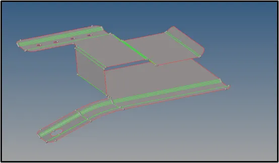
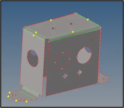
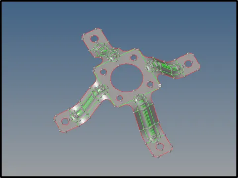
Midsurface meshing is opted for components where the geometry thickness is small when compared with the span length of the components, so if you see most of the automotive structures are of sheet metal and plastics, where the length of the component is large when compared to the thickness, hence for this reason we opt for mid surface extraction and assign the thickness of the component to the elements through properties on components method.
Use the Auto Midsurface tool to extract the midsurfaces for the given model. The Midsurface panel can be used to extract the midsurface of sheet metal stampings, molded plastic parts with ribs, and other parts that have thickness clearly smaller than width and length.
 Model 1
 Model 2
 Model 3
Step 4 :
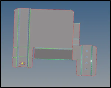
Geometrical Cleanup and Topology of Midsurface :
- Check for geomertrical errors in the midsurface.
- Check for missing surfaces and free edges and fix it using the neccessary tools.
- Use the Quick Edit panel to split surfaces and washers, change the category (shared, free, and so on) of edges, create or delete surfaces and points, project points, and trim fillets.
- Check for the surfaces that might fail for minimum length and defeature if required using the defeature tool.
- Use the Edge Fillets subpanel to identify and remove edge fillets. Similar to surface fillets, edge fillets create smooth curves at the intersection of relatively perpendicular free edges. You can identify them based on the radius of the fillet arc, and then remove them.
- Use the line toggle option to toggle lines wherever required.
- Use the replace point option, to move points from their current locations to the locations of other points, effectively combining them.
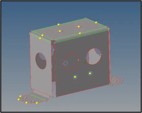 Model 2
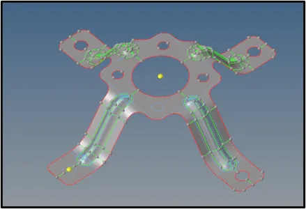 Model 3
Step 5 :
Meshing the component :
Meshing is an integral part of the engineering simulation process where complex geometries are divided into simple elements that can be used as discrete local approximations of the larger domain. The mesh influences the accuracy, convergence and speed of the simulation.
- Use the Automesh option to generate a mesh of plate elements using surface geometry or existing shell elements to define the mesh area.
- Set the options in the panel in any order that you feel comfortable using. Moving from subpanel to subpanel will not cause you to lose work. When you are finished making all your selections, click mesh to start the meshing process.
- Set the panel mode by selecting the appropriate subpanel.
- Select the meshing method by setting the entity selector to surfs or elems.
- Make the required element criteria settings.
- Set any algorithm options.
- Select the area to be meshed using the entity selector and any extended selection methods.
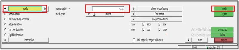
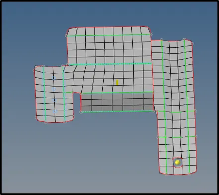 Model 1
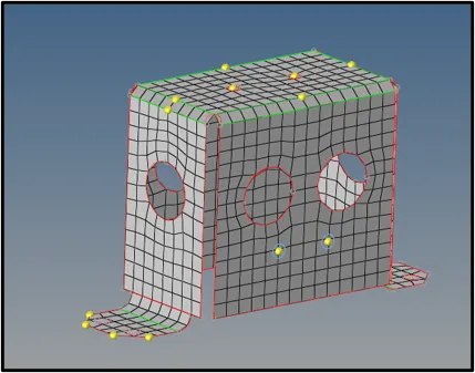 Model 2
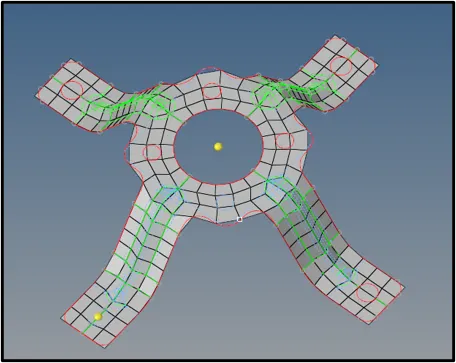 Model 3
Step 6:
Check for quality errors :
Use the Check Elems panel to verify the basic quality of your elements, as well as the geometric qualities of those elements.Each subpanel displays quality checks of a specific type, depending on dimensionality, time steps, and so forth. Each check is listed on a green command button; clicking the button performs a check and the results are summarized in the status bar.Criteria that you edit will be preserved even if you navigate to a different subpanel and then back again. However, criteria on different subpanels do not relate to each other, so changing the length requirement on the 1-d subpanel does not change the length requirement on the 2-d subpanel.Different checks are supplied to review the quality measurements of different types of elements. For example, if you have created a quad, it is possible that the quad has some degree of warpage. You can use the warpage function to check the element for warpage and to specify the maximum allowable warpage for that element.Another check available is for rigid loops. Use rigid loops to determine if a group of 1D rigid elements forms a loop. After it checks for instances where this has occurred, it highlights the elements that failed the test.
Criteria settings are stored and retrieved using a criteria file. You can save the results from the Quality Index (QI) panel to a summary file.

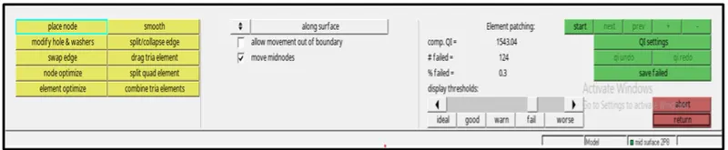
Step 7:
Check for Free edges :
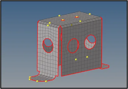
Free edges are defined as a pair of nodes identifying an element edge that are not shared with another element. Free edges are normally found around the outer perimeter of a part or around openings within the part. Free edges found in your model are displayed as red plot elements in their own component called ^edges.

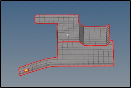 Model 1
 Model 2
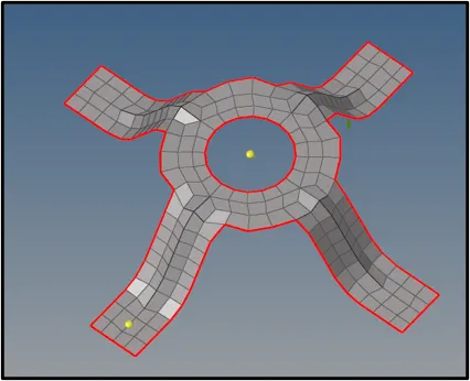 Model 3
Step 8:
Check for Normals :
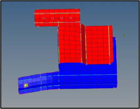
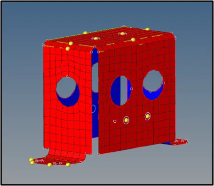
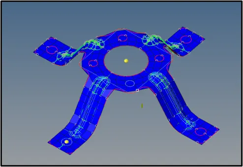
Use the Normals panel to display and reverse the normals of elements or surfaces. The orientation of element normals can also be adjusted. The normal of an element is determined by following the order of nodes of the element using the right-hand rule.For the Abaqus solver interface this panel can be used to adjust or reverse the stacking direction of continuum shells.Normals can be reviewed showing a vector or by colors. A vector shows in positive normal direction, while the color mode shows the positive side of a shell or surface in red and the negative side in blue.
Use the Elements subpanel to display and reverse the normals of elements. Select elements indirectly by components or directly by elements, or elect to have all of the displayed 2D elements selected automatically. Click display to review the current normal orientation of the selected elements. Optionally, click reverse to flip the normals to the opposite side (reverse the normals).You can also use the Elements subpanel to adjust element normals. Select elements to adjust, then select an orientation method which determines how element normals are adjusted. When you are finished, click adjust. Optionally, select display adjusted only to only display the elements which have been adjusted in this operation. All elements selected for adjusting must be in a continuous mesh for this operation.On review, normals are displayed with vectors by default. Alternatively, you can choose to display normals in color mode by switching the toggle from vector display normals to color display normals. Normals pointing in the wrong direction can be spotted easier in bigger meshes when using the color display mode. Red indicates the positive normal direction and blue indicates the opposite side of the element.In vector mode, specify the size of normals in the size field. If this value is zero, the normal is sized based on the smallest side of the element. If a value other than zero is specified for size, the normal is drawn based on the length specified in model units.

 Model 1
 Model 2
 Model 3
Step 9:
Assigning Thickness to elements :
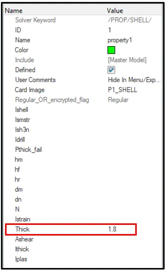
- After meshing, thickness needs to be assigned to the elements by creating new property.
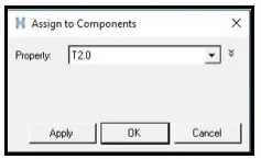
- Now assign the property to the required component.
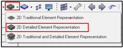
- Now, change the representation to 2D Detailed element representation.
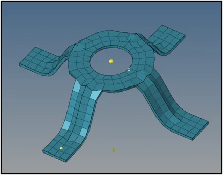 Model 1
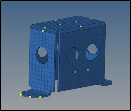 Model 2
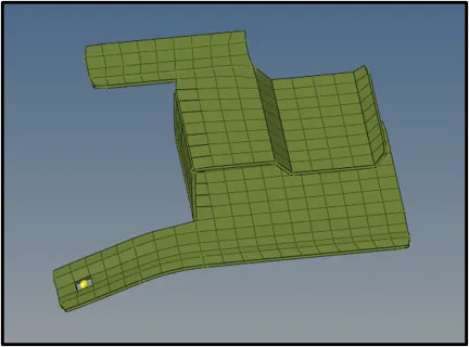 Model 3
Result:
For the above model, Midsurface was extracted and Meshing was done taking into account all the quality criterias and also assigning thickness to the elements.
Conclusion:
From the above Model we can conclude that before meshing, the model must be studied well that is all the geometrical errors must be cleared and then the midsurface must be extracted. During meshing, all the meshing rules must be followed, clearing all the given qaulity criterias.