Week 8-Challenge
MODEL 1 :
Aim :-
To check for the geometrical errors and mesh with the given element Quality criteria using tetra elements.
Given Quality Criteria :
Min. Lenght - 2mm
Target Lenght - 5mm
Max. Length - 7mm
Tet collapse - 0.15
Procedure:-
- Import .IGS file into ANSA
- Geometry check up and topology.
- Surface meshing
- Tetra meshing.
- Check for quality criteria.
Step 1 :
Import the given model into hypermesh using the import command.
IMPORT SOLVER DECK > IMPORT GEOMETRY > SELECT FILE TYTPE > IMPORT
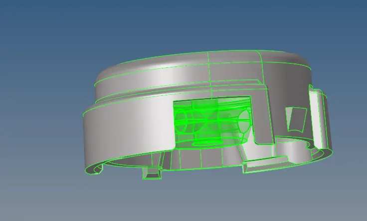
Step 2 :
Check for geometrical errors :
Now, check for the construction lines that might fail for quality errors and toggle the lines wherever neccessary.
Cleanup operations include the equivalencing of "red" free edges, fixing of small surfaces (relative to the element size), and detection of features such as beads. It also performs specified surface editing/defeaturing operations like the removal of pinholes (less than specified size), removal of edge fillets, and the addition of a layer of washer elements around holes.
The Quick Edit tools can be utilized with the option to force the immediate re-meshing of surfaces after a topology change (set in the Meshing Options panel accessible from the Preferences menu's, Meshing Options sub-menu; the setting is labeled topology revision on that panel.). Later, unwanted lines can be toggled using the toggle edge command.
Use the lines selector to select line(s).
- Left-click a free edge (red) to make it shared (green), or a shared edge to make it suppressed (blue).
- Right-click a suppressed edge to make it shared, or a shared edge to make it free.
In either case, the edge must meet the criteria for the type of edge you wish to change it to. For example, toggling a free edge to a shared edge requires the presence of a similar edge within the distance you specify in the tolerance field.
GEOMETRY > QUICK EDIT > TOGGLE EDGE > SELECT LINES
Check for unwanted lines and toggle it using the toggle edges option in the subpanel.
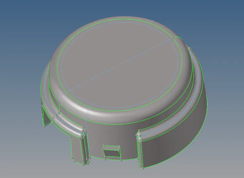 Blue lines in the figure indicates the toggled lines

Step 3 :
Surface Meshing :
Use the Automesh option to generate a surface mesh of plate elements using surface geometry or existing shell elements to define the mesh area. Enter the required quality criterias.
Set the options in the panel in any order that you feel comfortable using. Moving from subpanel to subpanel will not cause you to lose work. When you are finished making all your selections, click mesh to start the meshing process.
- Set the panel mode by selecting the appropriate subpanel.
- Select the meshing method by setting the entity selector to surfs or elems.
- Make the required element criteria settings.
- Set any algorithm options.
- Select the area to be meshed using the entity selector and any extended selection methods.
2D > AUTOMESH > SURFACE > TRIAS > ENTER ELEMENT SIZE > MESH
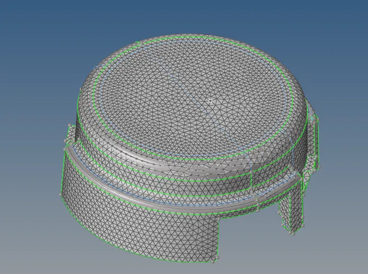

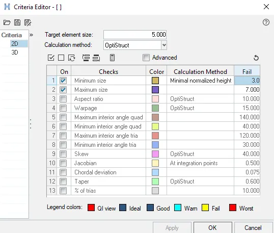
Step 4 :
Tetra Meshing :
For this component tetra meshing has to be performed as the midsurface had not been taken. Use the Tetramesh panel to fill an enclosed volume with first or second order tetrahedral elements.
A region is considered enclosed if it is entirely bounded by a shell mesh (tria and/or quad elements). Other element configurations generated in this panel are hexahedral, wedge, and pyramids. These elements are typically generated when you need boundary layer type meshes on certain areas of the volume surface.
3D > TETRAMESH > SELECT ELEMENTS > MESH
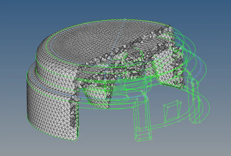

Use the Tetra Remesh subpanel to regenerate the mesh for a single volume of tetrahedral elements.The Free boundary faces option affects those faces of tetra elements which are on the outside of the volume, meaning the tetra faces which have only one tetra attached. Those faces are called free boundary faces.
3D > TETRA REMESH > SELECT ELEMENTS > REMESH

Step 5 :
Check for quality criteria.
Check for the tetcolapse error from the check elements tab in the subpanel below.
Tetra elements whose collapse value falls below the value specified are highlighted when the tetra collapse function is selected. These elements remain highlighted until the Check Elems panel is exited.Tetra collapse calculation: At each of the four nodes of the tetra, the distance from the node to the opposite side of the element is divided by the square root of the area of the opposite side. The minimum value found is normalized by dividing it by 1.24, and then reported. As the tetra collapses, this value approaches 0.0. For a perfect tetra, this value is 1.0.
CHECK ELEMENTS > 3D > CHECK FOR TETCOLLAPSE > SAVE FAILED > MASK > ELEMENTS > RETRIEVE > MASK > REVERSE.

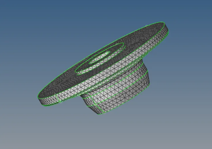
Clear the tecollapses by remeshing first and still if the tetcollapse does not clear, use the translate node option from the subpanel below. We can also try increasing the distance between the two nodes.
MODEL 2 :
We can mesh this model by using the quick tetra option. Same procedure needs to be followed as above but the for quick tetra meshing, surface meshing is not required as tetra meshing can done directly.
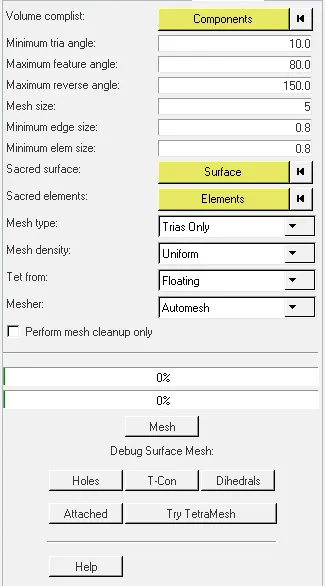
The Quick TetraMesh macro quickly creates a tetramesh of an enclosed volume defined by geometry and/or elements.Its main objective is to quickly and automatically create a tetramesh that meets the minimum interior angle and minimum element size. During the process of quick tetramesh, the mesh may deviate from the underlying geometry in order to maintain good quality elements. To alleviate this, you can select Sacred elements so that the tetmeshing function closely follows the original geometry.
VIEW > BROWSER > HYPERMESH > UTILITY > GEO/MESH > QUICK TETRAMESH > SELECT COMPONENTS > ENTER MESH SIZE > SELECT MESH TYPE AS TRIAS ONLY > MESH
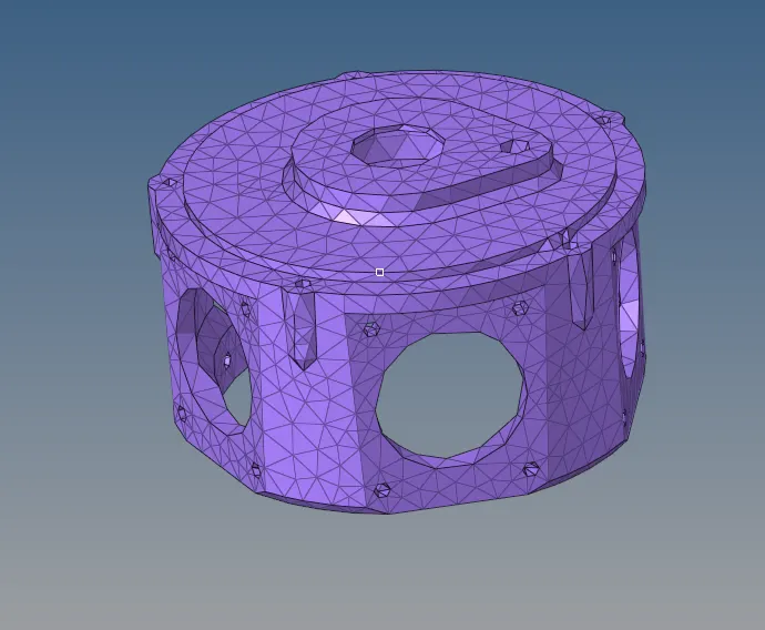
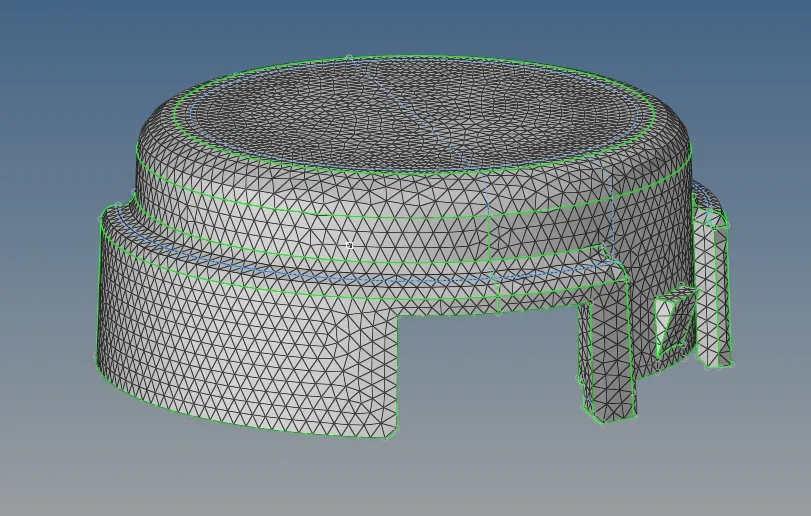
Check for the tetcollapse errors and perform the same operation as above to clear the tetcollapse.
Model 3 :
The blow model can be meshed using the volume mesh option from the subpanel . most of the time volume mesh gets realised only on solids.
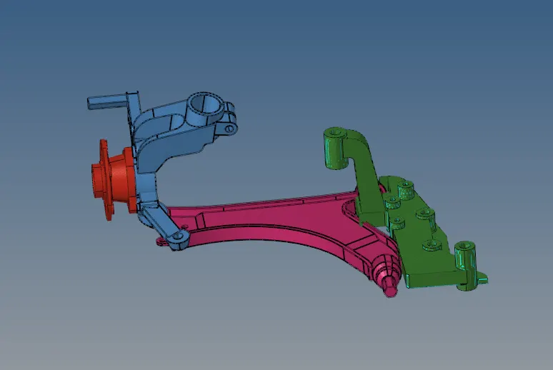
For the below component, we can observe that many fillets that fail for minimum length are present and hence these fillets needs to be removed. Geometry cleanup needs to be done fornthe below component in surfaces where tetcollapse occur.
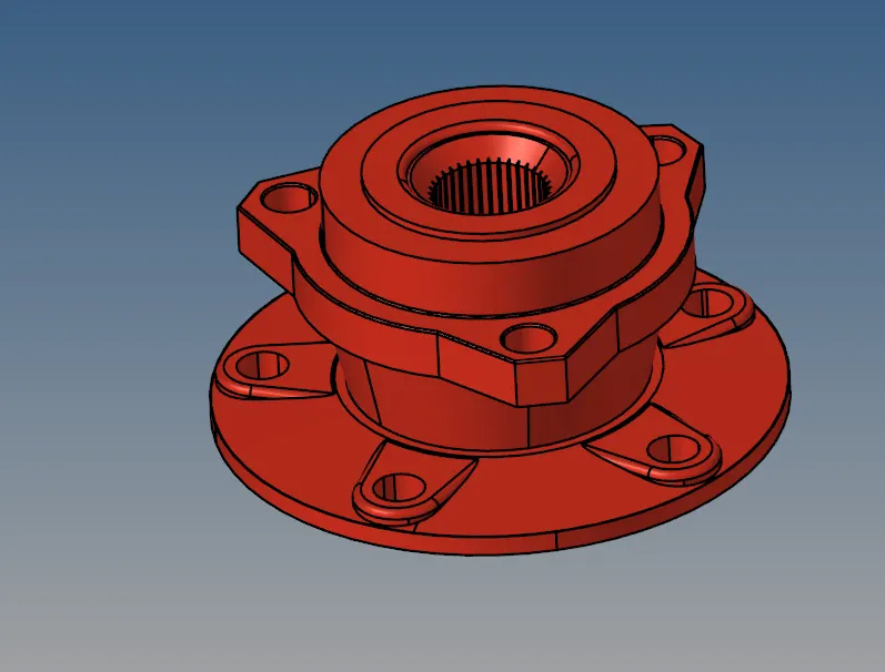 Before geometry cleanup
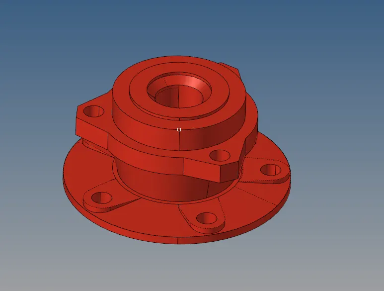 After geometry cleanup
Now, start meshing using the volume mesh or the tetra mesh.
Use the Volume Tetra subpanel to generate a shell mesh and fill the enclosed volume with solid elements.Given a solid entity or a set of surfaces representing a closed volume, this meshing option generates a shell mesh and fills the enclosed volume with solid elements. You can choose to create a shell mesh (2D) using quads, trias, or mixed elements and a solid mesh (3D) using tetrahedral elements only or mixed (tetras and penta) elements. In addition, you can use proximity meshing, which refines the mesh in areas where the features are small and closer together.
3D > TETRAMESH > VOLUME TETRA > SELECT SOLIDS > ENTER ELEMENT SIZE > MESH

Repeat the same procedures for the other components in the model.
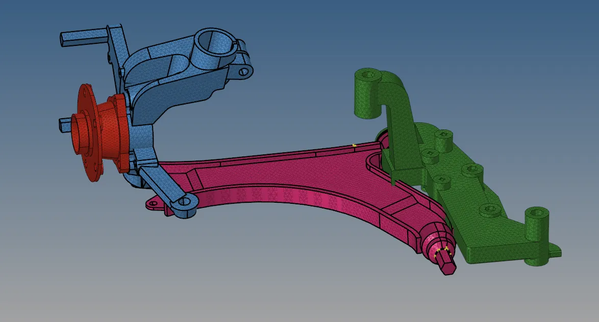 Final Meshed model
Result :
Hence, the tetra meshing is done for all the above components.