Assignment 3
1.Using the crash beam file from the previous assignment, change the run time to 55 ms.
• Import the given file into hyperworks.
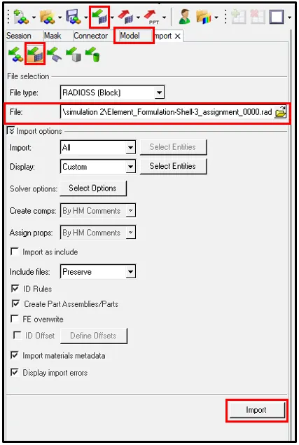
•The model will be imported.
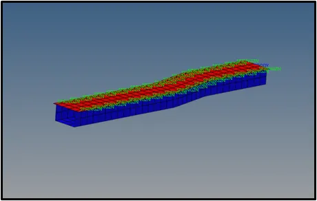
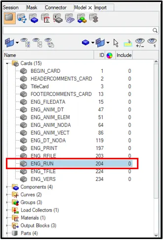
• Now, go to Model Browser > Cards> ENG_RUN
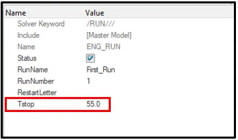
• Change the value of `T underset text(stop)` to 55 as mentioned in the questioned.
2. Change the number of animation steps during simulation to a minimum of 25 and maximum of 60.
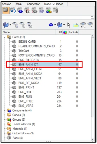
• Click on Model Browser>Cards>ENG_ANIM_DT
• The number of animation files required can be taken as 40.
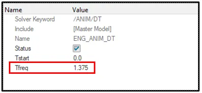
`T underset (fq)`=`frac{bb "Stop Time" underset(st)(T)}{bb "No of File Required (/ANIM/DT)"}`
`T underset (fq)`=`frac(55)(40)`
`T underset (fq)`=1.375
3. Run the base simulation without any modification to element properties.
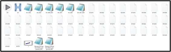
• From the subpanel below, click on Analysis > Select the save location > click Radioss.
• Simulation will start.
4. At the end of the simulation, do the energy error and mass error checks and determine whether results would be acceptable.
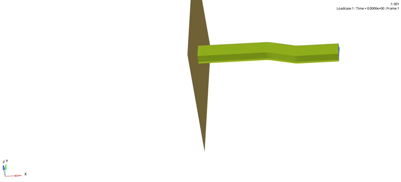
Open the save location file and click on the output file of the simulation to check for the Energy error and Mass error.
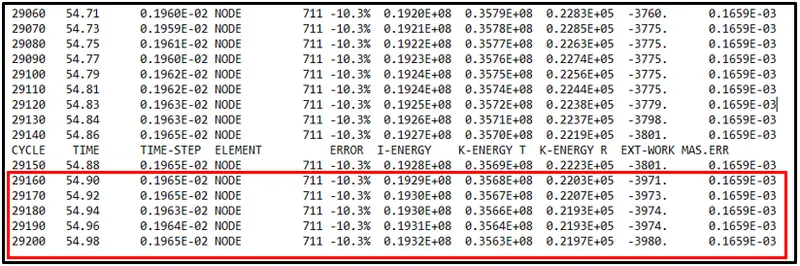
Maximum Energy error was found to be -10.3% and Maximum Mass error was found to be 0.1659E-03.
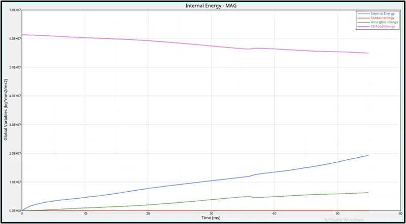
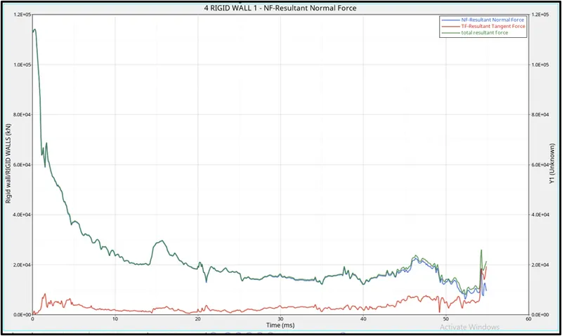
5. If acceptable, Plot rigid wall forces, internal energy, hourglass energy, contact energy, total energy of the simulations.
Graph for Internal Energy,Contact Energy,Total Energy and Hourglass Energy :
Rigid wall Forces graph :
6. Change all the shell elements properties to recommended properties, save this as separate, rad files and run the simulation.
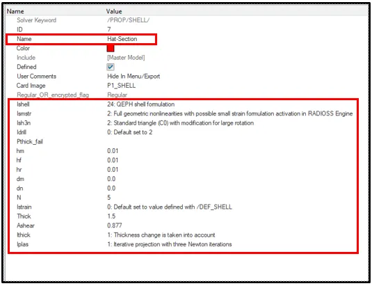
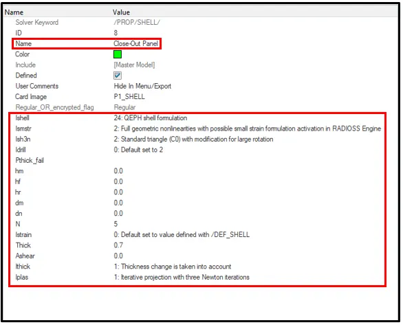
Recommended properties:
| Parameters | Comment | |
|
Ishell =24 |
QEPH 4 nodes shells are best combination of cost and accuracy. | |
|
Ismstr=2 |
Full geometric nonlinearities (default)with possible small strain formulation activation in RADIOSS Engine. | |
|
Ish3n=2 |
Standard 3 noded shell (C0)with modification for large rotation(default) |
|
| N=5 | Number of integration points set to 5 for accuracy bending. | |
|
Ithick=1 |
Thickness change is taken into account for accuracy. |
|
|
Iplas=1 |
Iterative plasticity for good accuracy. |
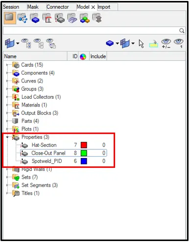
- Assign the above values for the propwerties .
Model Browser >Properties> Select Properties
7. Follow steps 5 and 6.
Now, simulate the model again by repeating steps as above.
- From the subpanel below, click on Analysis > Select the save location > click Radioss.
- Simulation will start.
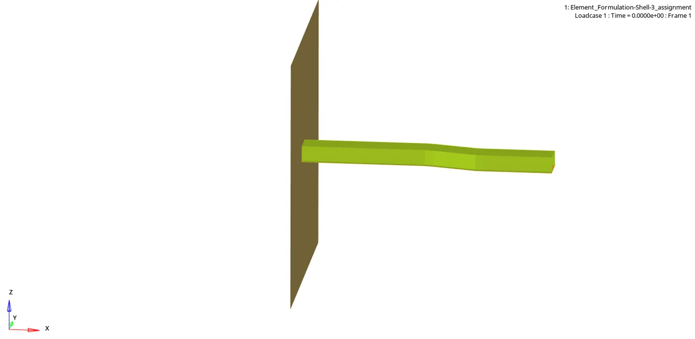
- Open the save location file and click on the output file of the simulation to check for the Energy error and Mass error.
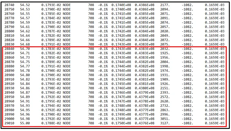
- Maximum Energy error was found to be -0.1% and Maximum Mass error was found to be 0.1659E-03.
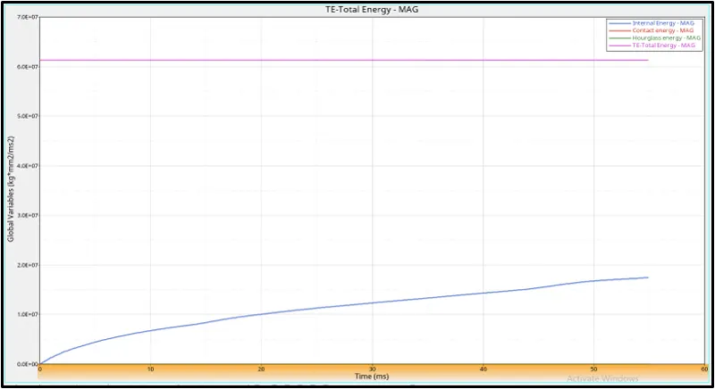
Graph for Internal Energy,Contact Energy,Total Energy and Hourglass Energy :
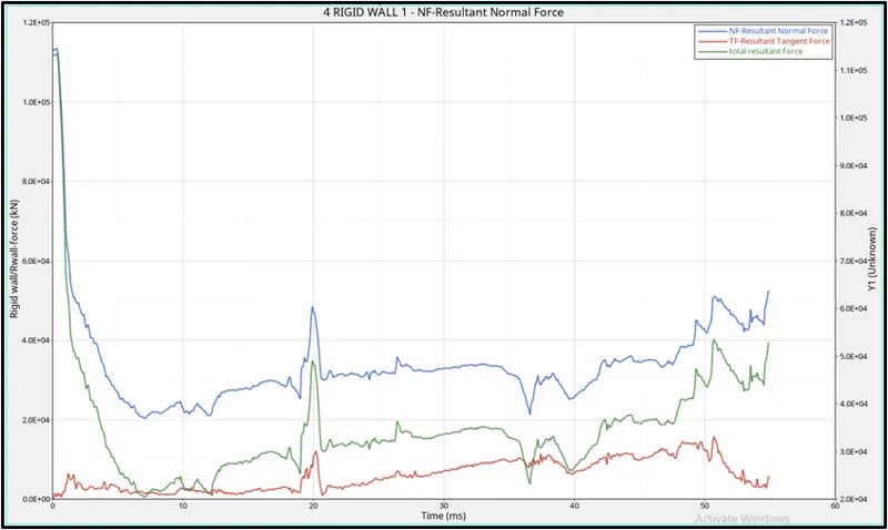
Rigid wall Forces graph :
8. Create a brief report comparing all the results from steps 5 and 6 for both simulations.
- The energy error for the base simulation was found to be -10.3% whereas for the integrated shell element simulation it was found to be -.01% which is a very small error.
- From the graph, we can see that the total energy for the base simulation gradually decreases as there is increase in time, whereas for the integrated shell element simulation the total energy remains constant.
- From the graph, we can see that the hourglass energy for the base simulation increases with the increase in time and for the integrated shell element simulation the hourglass energy remains constantly at zero.
- From the graph, we can see that the contact energy for the base simulation keeps varying throughout, whereas for the integrated shell element simulation the contact energy remains constantly at zero.
- From the graph, we can see that the internal energy for the base simulation and as well as for the integrated shell element simulation, keeps increasing gradually with increase in time.
9. Comment whether there is any change in the results and why there is any change in the result.
The major difference between both simulation is the difference in energy error or the hourglass error. Hourglass error is caused when the under-integrated shell element, displacements and forces may exit for each node of the element, like the sum of all these forces and displacements give null strain and stress on the integration point of the element. This problem exist only for under-integrated element.
Finally, we can conclude that the integrated shell element simulation produces better results when compared to the base simulation because the QEPH shell reduces hourglass error and the cost of ithe process is reasonable,