2D Meshing using HyperMesh
Aim: To carry out geometry cleanup of the models and 2D meshing by extraction of the mid surface.
Objective: Cleaning up the geometry and extracting mid surface. Meshing is done with a target length of 5mm with Quality criteria (min 3.5mm and max 7mm).
Procedure: Given three models are loaded on HyperMesh software with the Radioss interface and worked on them individually. The working procedure is as follows:
Geometry Cleanup:
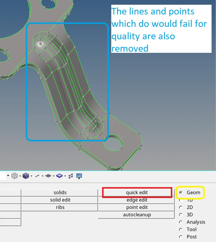
Using the Quick Edit option (red box in the image below) from the Geom module (yellow box in the image below) the given model is cleaned up. The unnecessary lines and points (blue box in the image below) which do not affect the geometry features are removed. The lines and points (blue box) which do would fail for quality are also removed, but care is taken that defeaturing is not affecting the geometry.
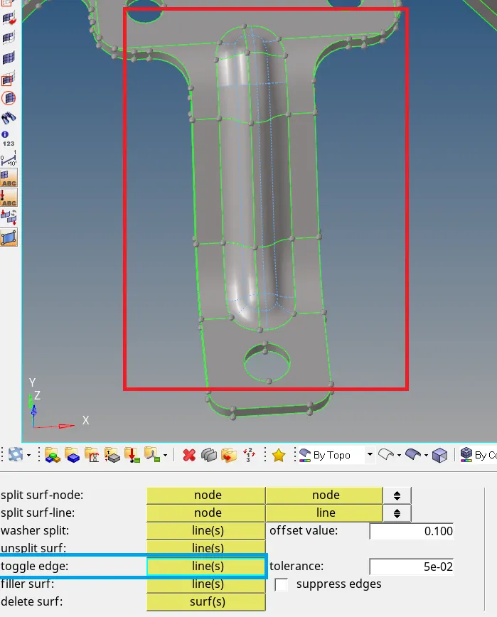
In the Quick Edit, the toggle edge option (blue box in the image below) is used to remove the lines (red box).
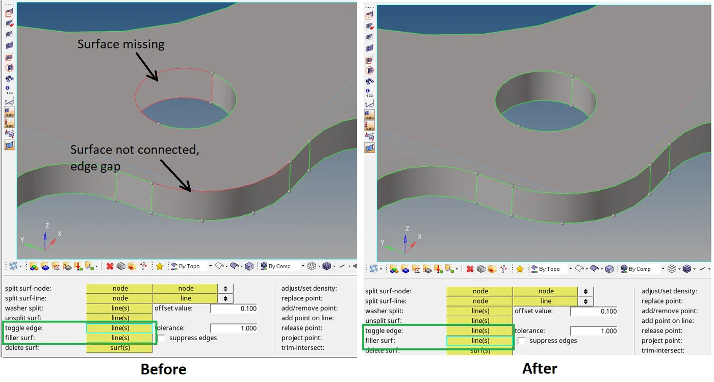
In the topo view if there are red lines representing the edges then it means the geometry is not closed. This could happen because of two reasons:
1. The edges of the two adjacent surfaces are not connected to each other and create a gap or,
2. The surface/ face would be missing. (see the image below)
The gap due to edges can be filled up by toggling the edges using toggle edge and the missing surface can be generated using filler surf (green box in the image below).
Mid-Surface:
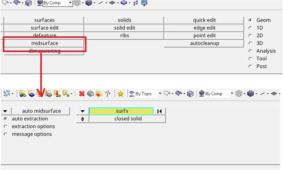
After completing the geometry cleanup, in the same module (Geom) the midsurafce option is used to extract the mid surface of the geometry.
Using auto extraction the mid surface is extracted by selecting the entire geometry as shown in the image below:
But the auto extraction was not able to capture the features properly and ended up giving and distorted mid surface from the original geometry as shown in the image below:
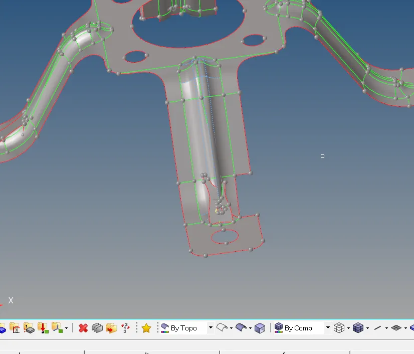
So the mid surface was rejected and the new mid surface was extracted manually.
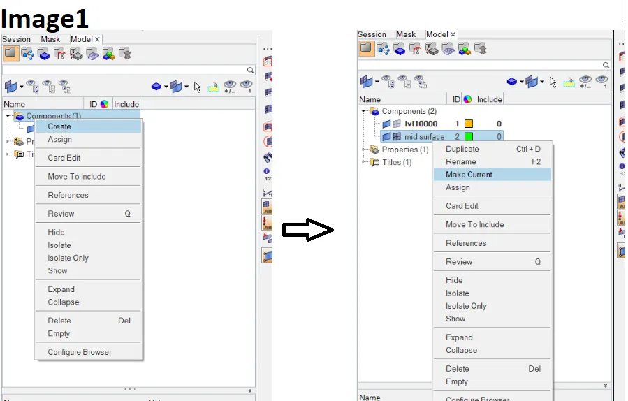
1. A new component is created and named as the mid surface in the model tab. The new component is assigned as current (see Image1 below).
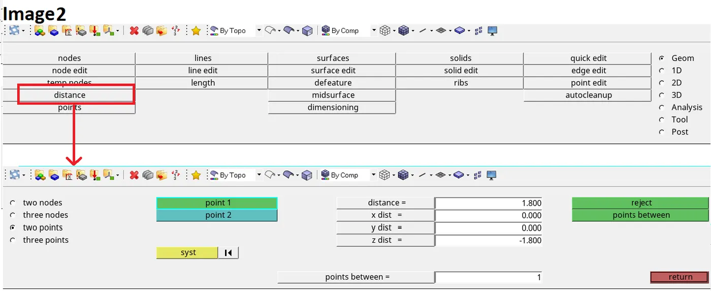
2.To offset the surface to the midplane of the geometry, the thickness was measured using the two points option in the distance tool of the Geom module and found out to be 1.8mm (see Image2 below).
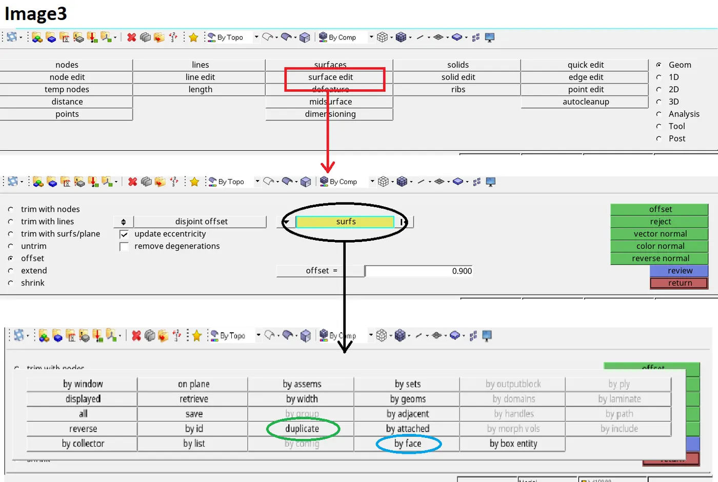
3.Using the offset option from the surface edit tool in the same module (Geom). The surface from one side was selected using surfs by face (see the blue circle in Image3 below).
4.After the selection of the surface to be offset, by clicking on surfs the window pops up and the duplicate (green circle) of the selected surface is created (see Image3 below).
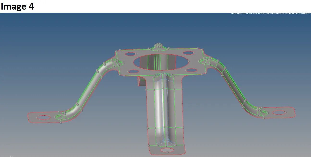
5.Then the offset value is given i.e., half of the thickness value (0.9mm) in the negative direction, and the surface is offset (see Image4 below).
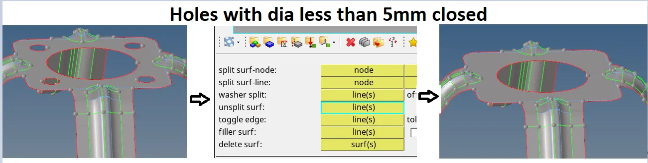
If the mid surface has some points, lines, and other features that need defeaturing is done. The holes dia less than 5mm can be ignored, therefore those holes are closed using unsplit surf from the quick edit option Geom module. The edge fillets can also be removed using the defeature option.
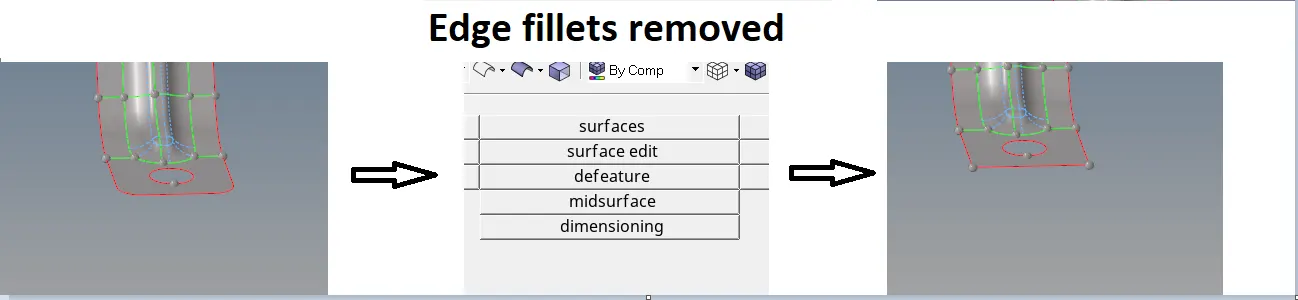
The edge fillets can also be removed using defeature option.
Meshing:
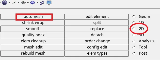
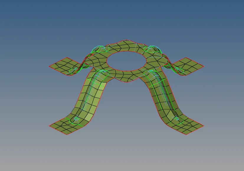
After the mid surface is extracted the meshing is done using automesh in the 2D module.
The element size is 5 as the given target length is 5.

Complete meshed model.
Quality Criteria:
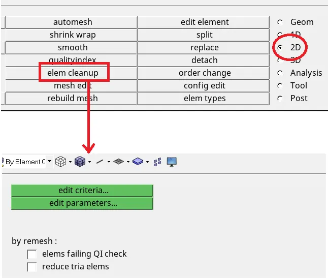
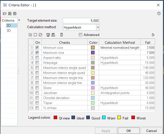
The given quality criteria (element size min 3.5 and max 7) were assigned as follows.
2D--> elem cleanup-->edit criteria...
After clicking the edit criteria a window pops up shown below and the given criteria values are entered and applied.
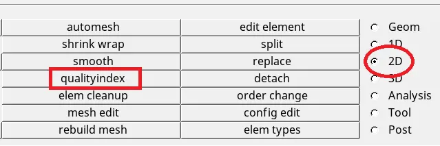
Now the elements which have failed for given quality is checked as follows.
2D-->qualityindex
Elements which have failed are shown in the image below:
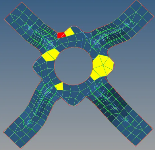
Following tools can be used to clean up the failed elements as follows:
2D-->qualityindex-->cleanup tools
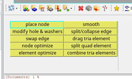
Using the above options the mesh quality can be improved by splitting elements, moving nodes and eliminating trias, and forming them into quad elements.
The tria can be moved through the mesh using the drag option.
Elements flow and optimization can be improved using node optimize and element optimize.
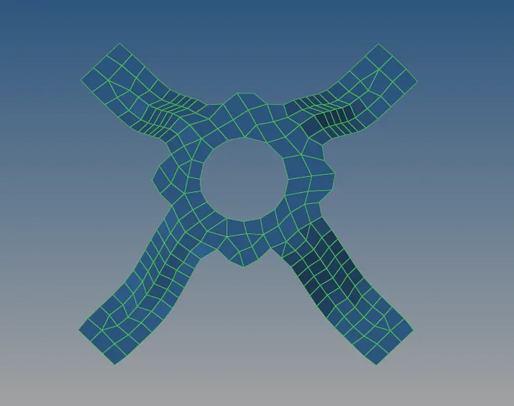
After resolving the quality issues, the mesh looks as follows:
There is a possibility that duplicate elements can be formed while remeshing, these can be identified and removed as follows:
Tool-->check elems-->duplicates
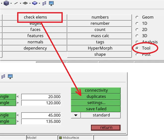
There were no duplicate elements found in the model.
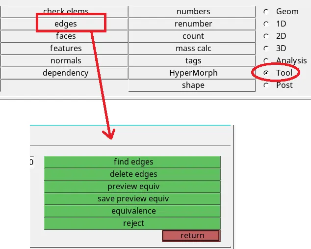
There is also a possibility that the elements maybe not be connected when 2 surfaces are meshed separately and nodes may not be aligned. To check that the following steps are followed.
Tool-->edges-->select elements-->find edges
-->delete edges (if no edges are marked in red color at the junction of two surfaces)
-->preview equiv-->equivalence-->delete edges (if red color lines are found)
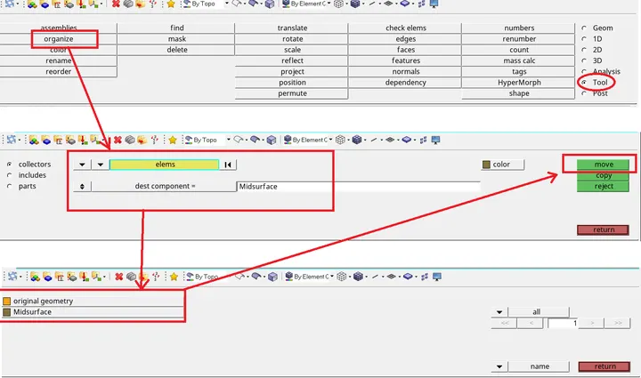
Once all quality checks are done the mesh has to be translated to the original geometry. It is done as follows:
Tool-->organize-->select elements-->dest component=-->original geometry-->move
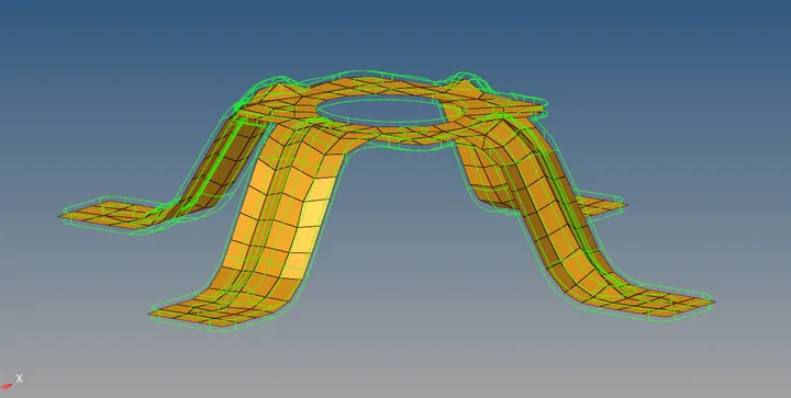
The mesh is translated to original geometry as seen in the image below:
To assign proper thickness, by creating a generic property right click on the Prop_Id in the card of the original geometry. By clicking on Create/Edit, the Edit Properties window pops up as shown in the image below:
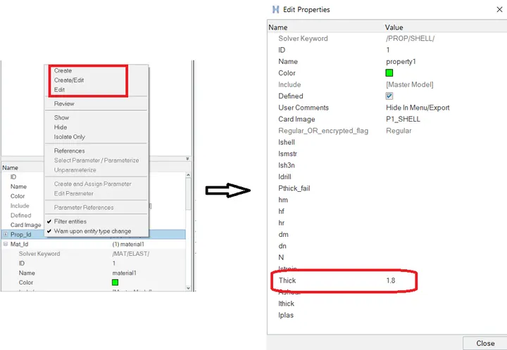
The thickness of the component is assigned as 1.8 as measured before.
This ends the process of mid surfacing and meshing and is ready for the solver.
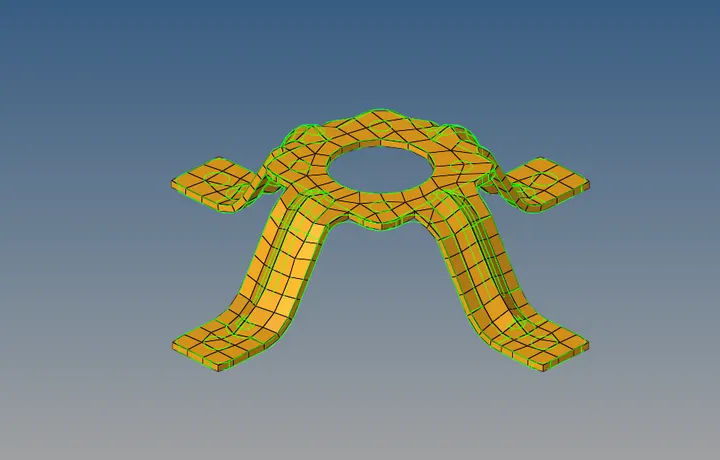
The component when viewed in 2D Detailed Element Representation is as follows:
Similarly, the other two components were processed.