Creation of 1D Connectors using Hypermesh
Creation of different types of 1D connectors on a truss model using Hypermesh
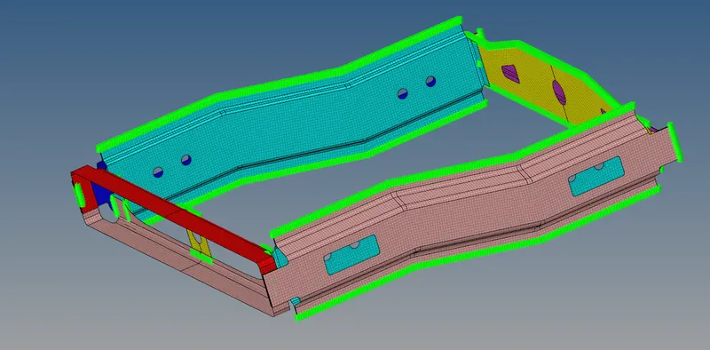
The given model was opened in Hypermesh and the model is as follows:
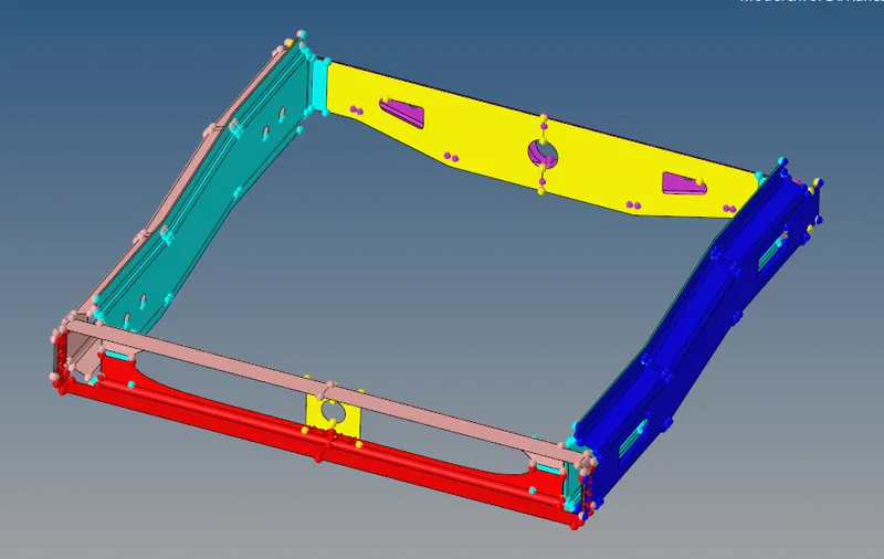
The model mesh using the 2D mesh auto mesh tool with the element target length of 5mm.
The meshed model looks as follows:
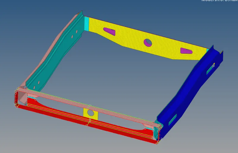
The rails and trusses have no connection between them, using 1D connectors the rails and trusses were connected.
The connections realized were as follows:
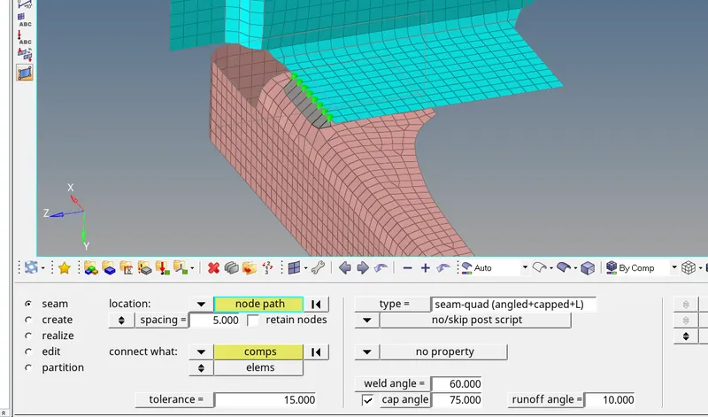
1. Right_Rail_2 & Front_truss_1:- Seam-Quad(angled+capped+L)
- In the connectors menu, the seam tool was used in which type of seam was selected as Seam-Quad(angled+capped+L).
- The nodes on one of the surfaces are selected.
- The spacing of 5 was kept as the mesh length was also 5.
- The comps selected here are the components between which the connection is to be realized.
The image below shows the realized connection for said type of connection.
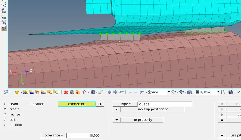
2. Left_Rail_2 & Front_truss_1:- Quad elements
In the same tool i.e. seam type of connection is changed to quads and the connection is realized as done in 1st case.
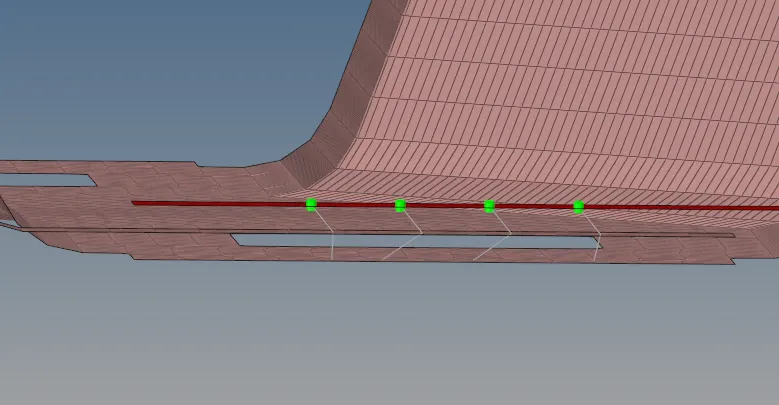
3. Front_truss_2, Front_truss_1 & Right_Rail_1:- Spot weld with 3 Layers and 5 mm Diameter
The spot weld tool is available under the spot tool in the connectors menu. The procedure followed here is also the same as done previously. The type of spot is changed to weld. The number of layers required is 3 so the num layers is set to total3
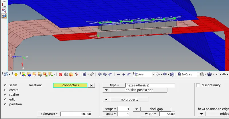
4. Front_truss_2, Front_truss_1 & Left_Rail_1:- Hexa (Adhesive)
The Hexa (Adhesive) is available under the seam and the procedure is the same for realizing the connection.
5. Rear_truss_2 & Right_Rail_2:- Bolt Connector
The bolt tool is available under the connectors menu. The procedure is similar to what was done in previous connections, selecting nodes and the components. The mesh doesn't have any holes so the setting is changed to create hole if none. Refer to the image below.
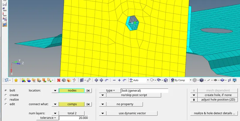
It is seen that the mesh flow is disturbed, so the area is remeshed again to have better mesh flow. The below image shows remesh of the components.
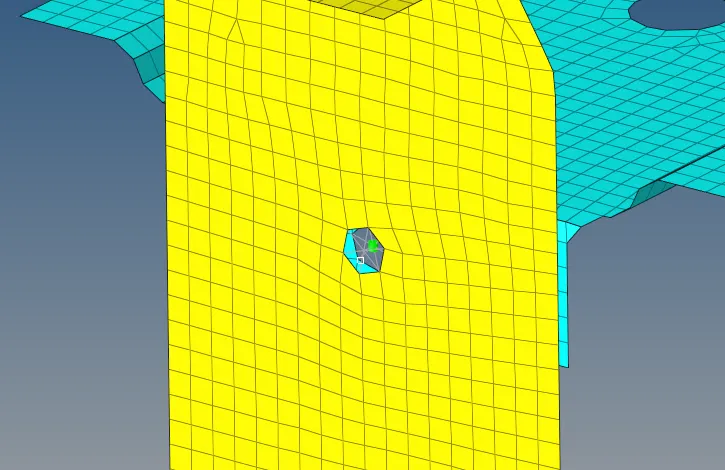
6. Rear_truss_2 & Left_Rail_2:- Bolt Connector
The connection is the same as what was done in the previous connection.
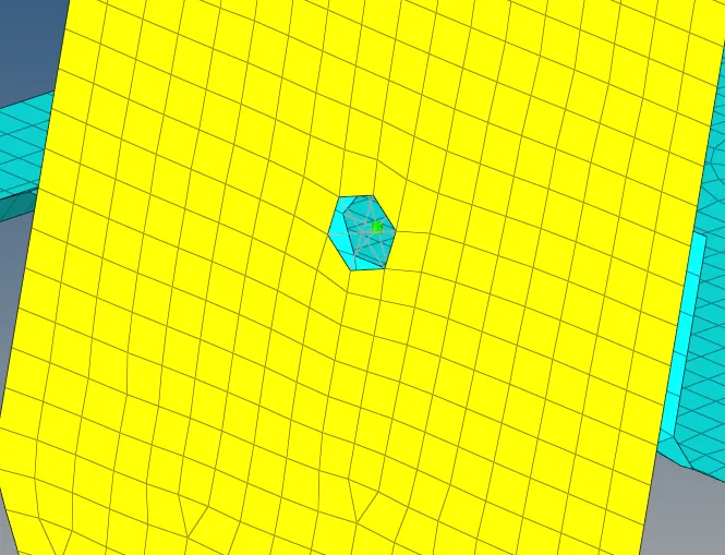
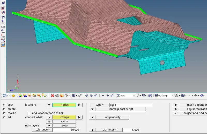
7. Right_Rail_1 & Right_Rail_2:- Spot-weld with Rigid Elements
This type of connection is done using rigids from the types of connection in the spot menu. The process of realizing the connection is the same as done in spot weld. Nodes from both components are chosen.
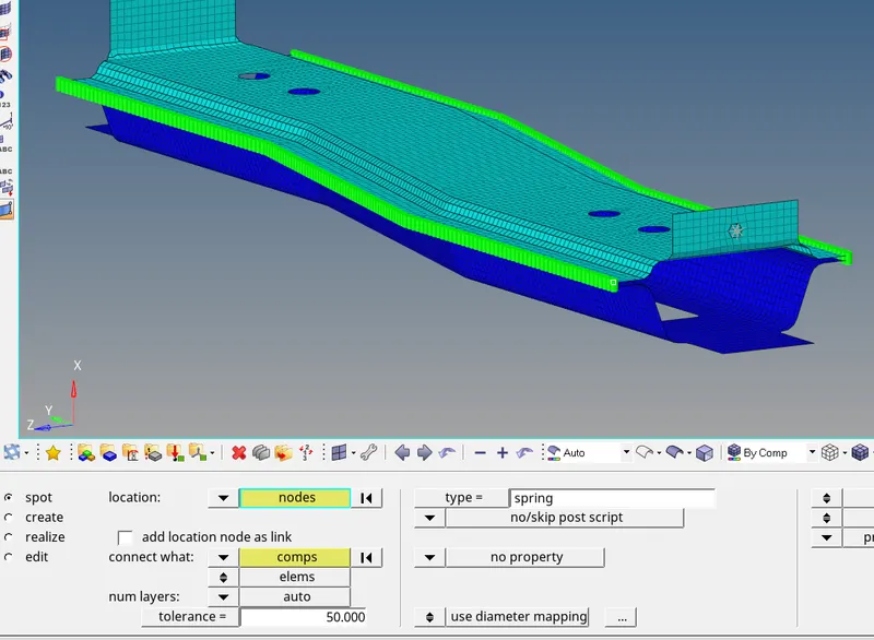
8. Left_Rail_1 & Left_Rail_2:- Spot-weld with Spring Elements
Just changing the type to spring by following the process followed in the previous connection Spot-weld with Spring Elements can be realized.
Rest all the components left to be joined are connected using spot weld. The image below shows the model with all connections are realized.