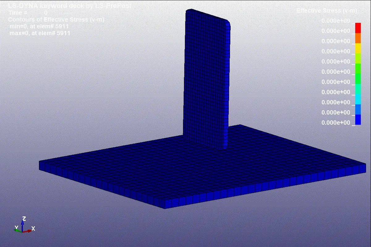
Simple Drop test of Mobile using LS DYNA
Aim: To perform a simple drop test of mobile using the given FE model using LS-Dyna solver.
Objective: To set up the material card, initial velocity to the mobile, and run the simulation to perform a simple drop test using LS-Dyna solver.
Procedure:
The given FE model is loaded in LS-PrePost software and the model looks as follows:
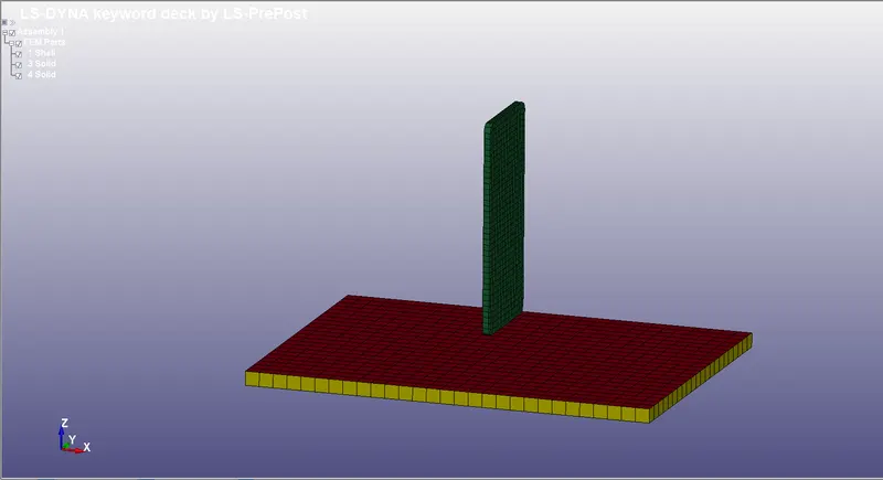
It is observed that FEM parts have shell parts and solid parts. The shell elements belong to the rigid wall which also has solid elements so the shell element is deleted and the 2 solids are renamed to avoid confusion between the mobile and the rigid wall.
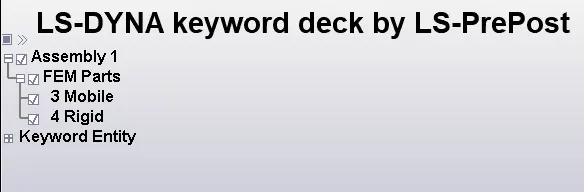
Now the keyword entities are created to have the desired simulation in the following steps:
- Creating Material cards for mobile and setting up the rigid wall.
- Assigning initial velocity to the mobile.
- Establishing surface contact between mobile and the rigid wall
- Defining section card
- Defining Control card
- Desire output cards using DATABASE card
Creating Material cards for mobile and setting up the rigid wall
The material cards for both the mobile and the rigid wall are defined using the MAT card. The material card for mobile is as follows:
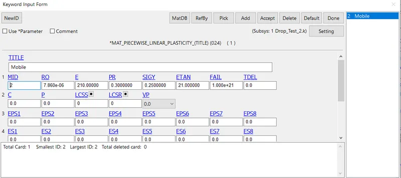
Material card for the rigid wall is as follows:
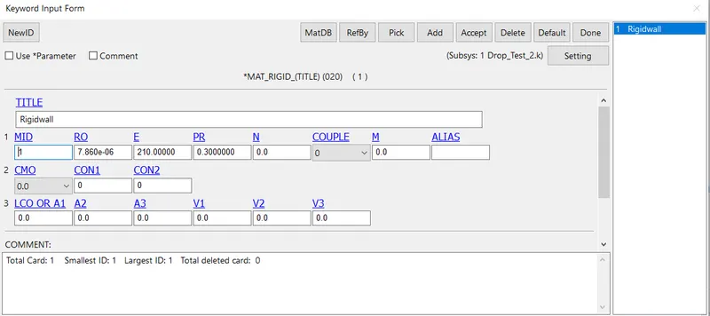
The unit system used here is kg mm ms.
Assigning initial velocity to the mobile
The initial velocity considered here is 10m/s. To maintain the consistent system of units the velocity is converted to kg mm ms system. The value of initial velocity remains unchanged in this case.
The mobile has to travel in the negative z-direction so -10 in VZ is assign in the initial velocity card. Under keyword INITIAL the velocity card is available. The card is shown below.
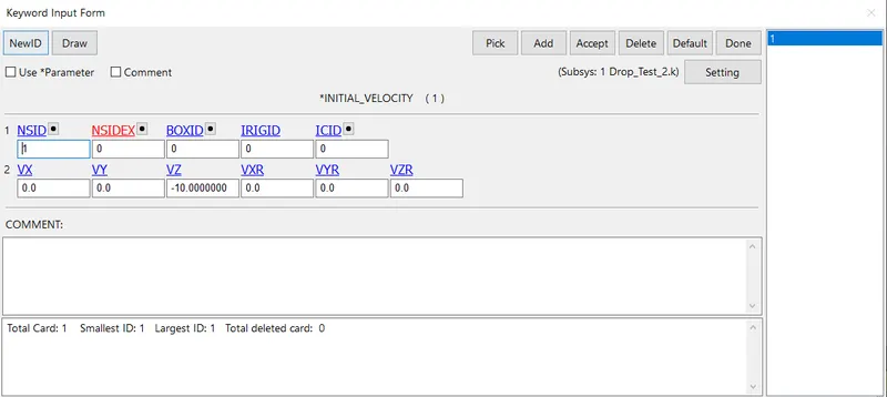
It is seen that NSID (Node Set ID) is assigned with 1. The node-set is created before assigning the initial velocity. This can be created using the keyword SET and selecting NODE_LIST. The set card is as follows:
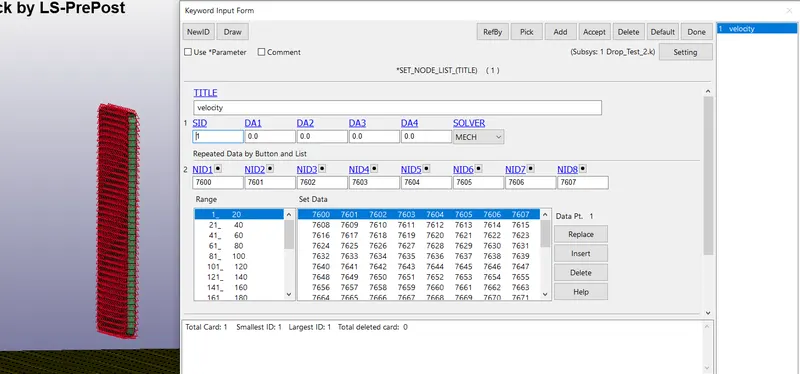
The red color in the image above represents the nodes selected for the particular node-set.
Establishing surface contact between mobile and the rigid wall
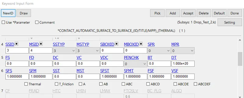
The mobile will experience impact only after coming in contact with the rigid wall. The surfaces of both the mobile and the rigid wall should have a contact interface. This contact is established using the keyword CONTACT_AUTOMATIC_SURFACE_TO_SURFACE. The slave set id (SSID) would be the mobile and the rigid wall which always happens to be the master set id (MSID) are assigned with respective part id number as shown below:
Defining section card
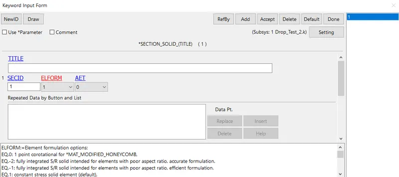
The element formulation, integration rule, nodal thicknesses, and cross-sectional properties are defined in the SECTION card. The model has only elements so the section card for solids is created and the card is as follows:
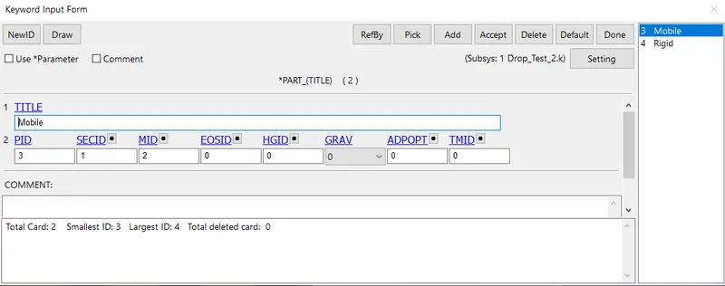
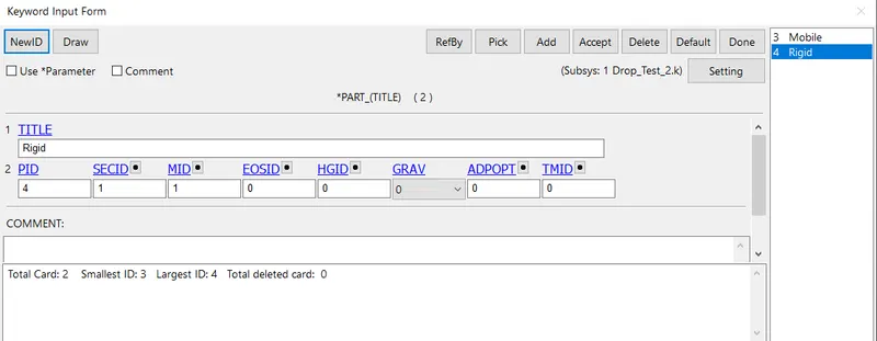
The section and the material cards are assigned to the part by inputting the MAT id and SECTION id in the prat card as follows:
Defining Control card
The control card is used for assigning the run time of the simulation. The keyword CONTROL_TERMINATION is as follows:
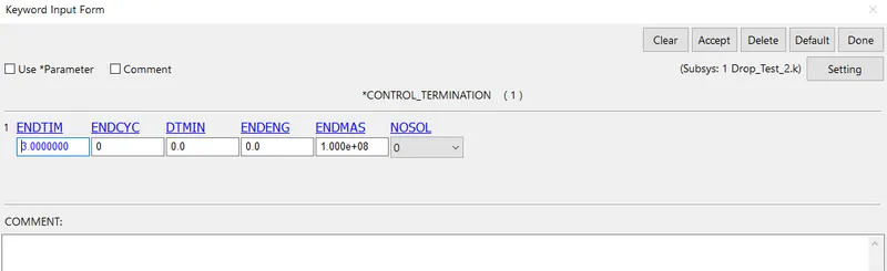
The run time for the simulation is set to 3ms.
Desire output cards using DATABASE card
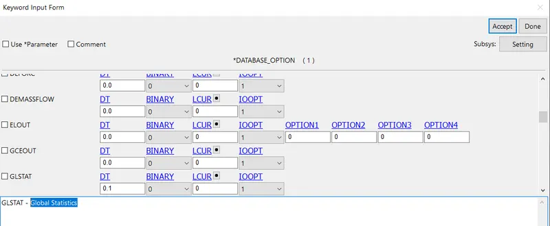
The DATABASE card has necessary to obtain output files containing results information. The Global Statistics at the time interval between outputs (DT=0.1) is collected in the output file. This is activated using the DATABASE_ASCII_OPTION card. The card is as follows:
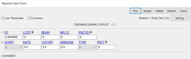
For animation file to generate DATABASE_BINARY_D3PLOT is used. The animation file is printed at the time interval between outputs (DT=0.05). The card is as follows:
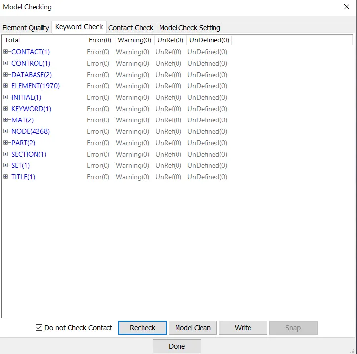
The model is checked using the CHECK MODEL option in keyword manager. The model had no errors and can be seen in the image below:
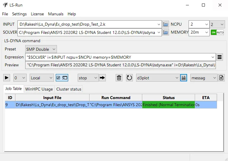
After the model check, the model is ready for simulation. The file is saved in .k format. and opened in LS Run and run for simulation.
The simulation results are as follows:
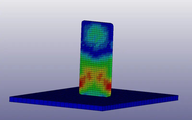
Animation