Modelling Spotwelds
Spot weld simulation using LS DYNA
Aim: To compare spot welds in the form of beam elements and solid elements.
Objective:
- To create a spot weld connection between two plates in the form of beam elements.
- To create a spot weld connection between two plates in the form of solid elements.
- Comparing axial and shear force between solid and beam elements under the same simulation condition.
Procedure
The model is loaded in LS PrePost and the model looks as follows:
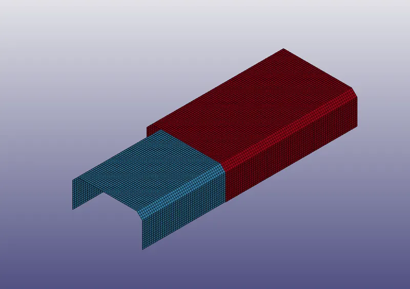
The model has two plates overlapping each other but a gap separation. The plates are connected using beam elements or solid elements and these elements are given spotweld material properties.
Spotweld_BEAM
The plates are connected with each other using beam elements using the Element Editing option in Element Tools. The Elem Type is set to beam and N1 and N2 nodes are selected from upper and lower plate respectively. Refer to the image below:
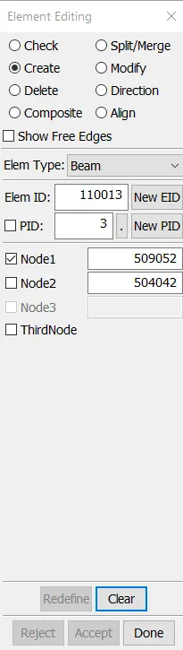
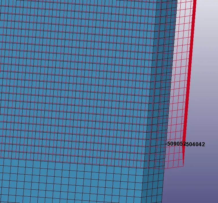
The beam element is created at 7 different places as shown below:
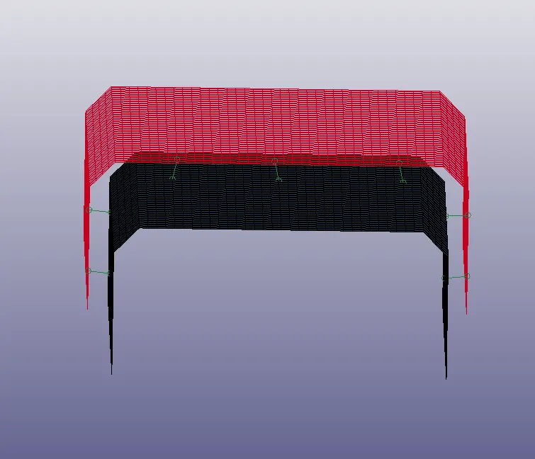
After the connections are created, the material modeling is done.
The MAT Keywords are created for the model. The plates are assigned MAT_PIECEWISE_LINEAR_PLASTICITY card and the beam is assigned MAT_SPOTWELD card. They are as follows:
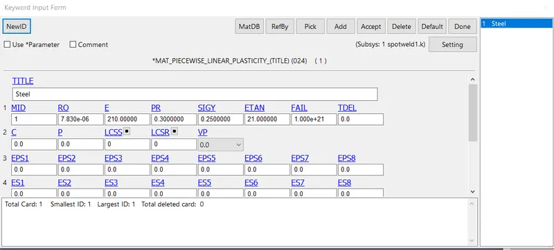
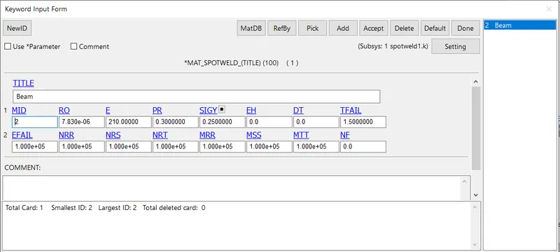
The TFAIL input is given as 1.5 as the simulation is for 3ms and as per the requirement, the spot weld failure must occur at half time of the simulation.
Section keywords for the shell elements and beam elements are created. The shell and beam are given a thickness of 1.5 mm and the cards are as follows:
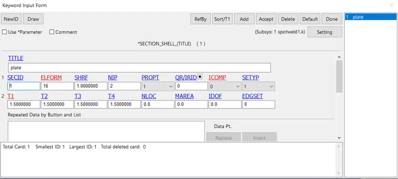
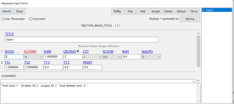
The SECID and the MID are assigned to respective parts in the PART keyword.
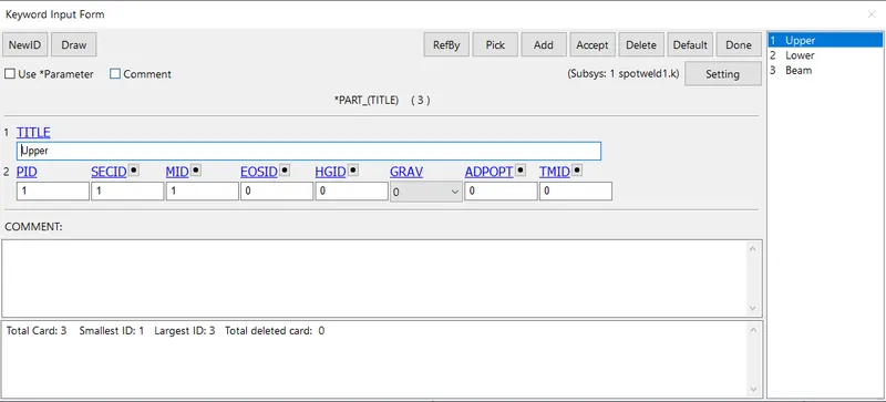
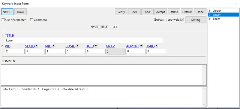
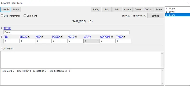
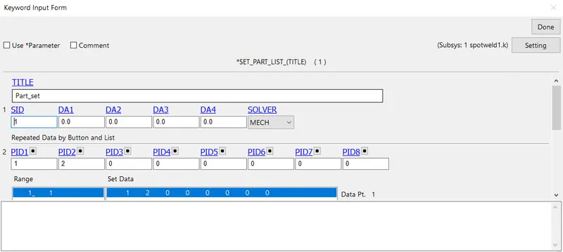
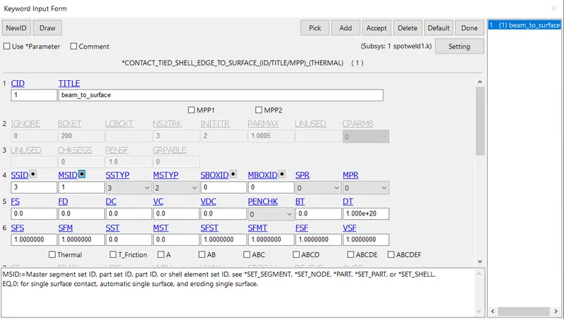
CONTACT card is created to establish contact between the plates and the beams. Using the CONTACT_TIED_SHELL_EDGE_TO_SURFACE keyword the contact is established. The simulation is to study spot weld so the beams are assigned slave and the plates are assigned, master. The master id for more than one PID is not possible to overcome this a set of parts is created and the set ID is given as input to the Master set.
PART LIST card:
The CONTACT_TIED_SHELL_EDGE_TO_SURFACE card is as follows:
The boundary conditions are assigned to the plates by constraining the lower plate and the upper plate in motion. Using Boundary Spc and Boundary Prescribed Motion the containing of the lower plate and the motion in the upper plate is achieved respectively.
Boundary Spc
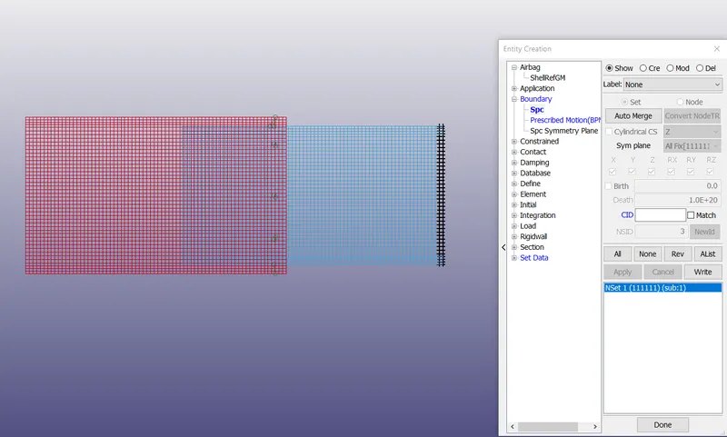
The NSet1 highlighted in blue color in the image above reads NSet1 (111111) means the set of nodes are constrained in all DoF. The black highlighted in the lower plates shows the set of nodes that are constrained.
Boundary Prescribed Motion
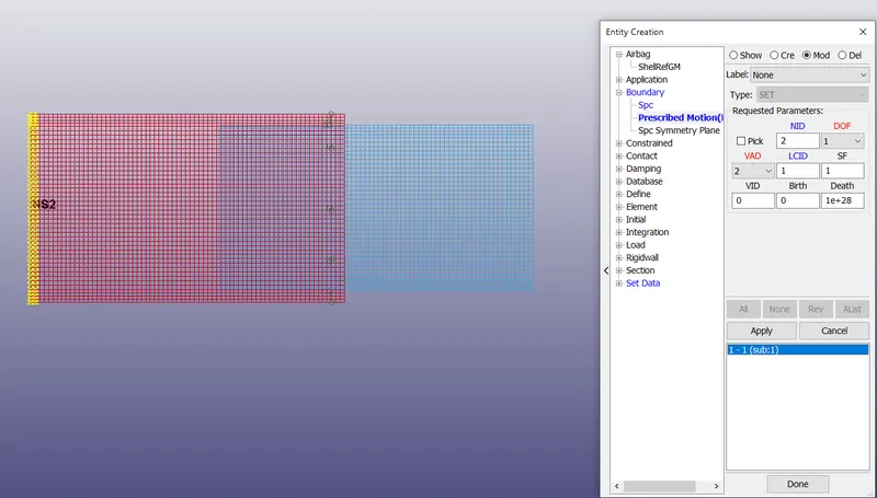
The yellow highlights in the upper plate show nodes that are assigned displacement.
The DOF is set to 1 which is the applicable degrees-of-freedom is x-translational DOF.
VAD is set to 2 which is motion is in the form of displacement(rigid bodies and nodes).
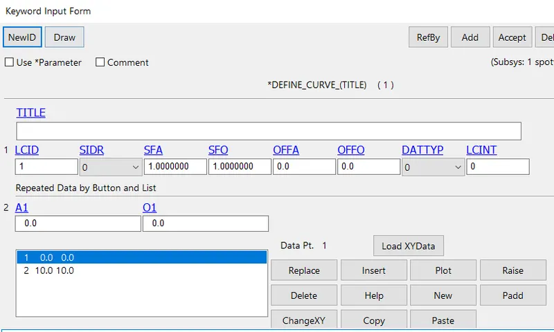
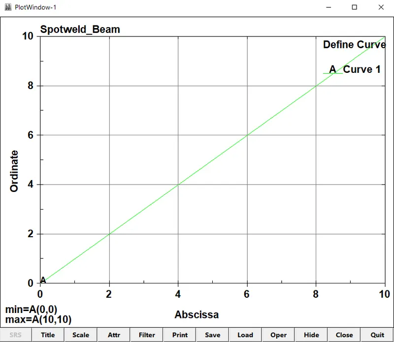
LCID (Load curve ID) is a defined curve.
The defined curve is created using the DEFINE_CURVE card and is as follows:
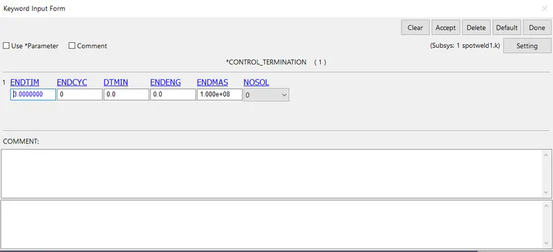
The Control card is created to set the simulation run time. The run time of 3ms is inputted in the CONTROL_TERMINATION keyword and is as follows:
For desired outputs from the simulation can be obtained using the keyword DATABASE_ASCII_option.
The GLSTAT for Global Statistics, MATSUM for Material Energies, SWFORC for Spotweld Nodal Constraint Reaction Forces are activated with DT set at 0.1.
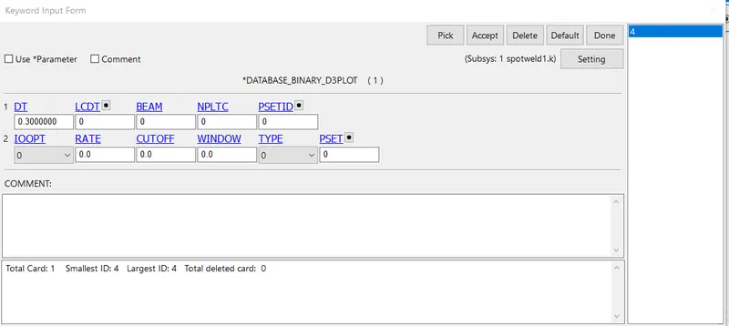
For the animation of the simulation, DATABASE_BINARY_D3PLOT is created with DT set at 0.3.
The model is checked after setting up all the keyword cards before running the simulation using Model Check.
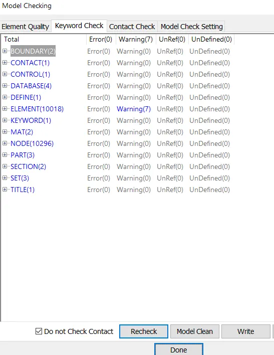
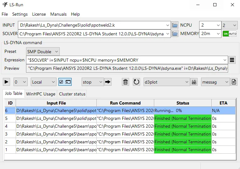
The model is error-free and is ready for simulation. The model is saved in .k file format and run in LS RUN.
Spotweld_SOLID
The modeling of spotweld in the form of solid elements is the same as what was done in beam elements instead of creating beam elements solid elements are created and the rest of the procedure is the same.
Creation of Solid Elements:
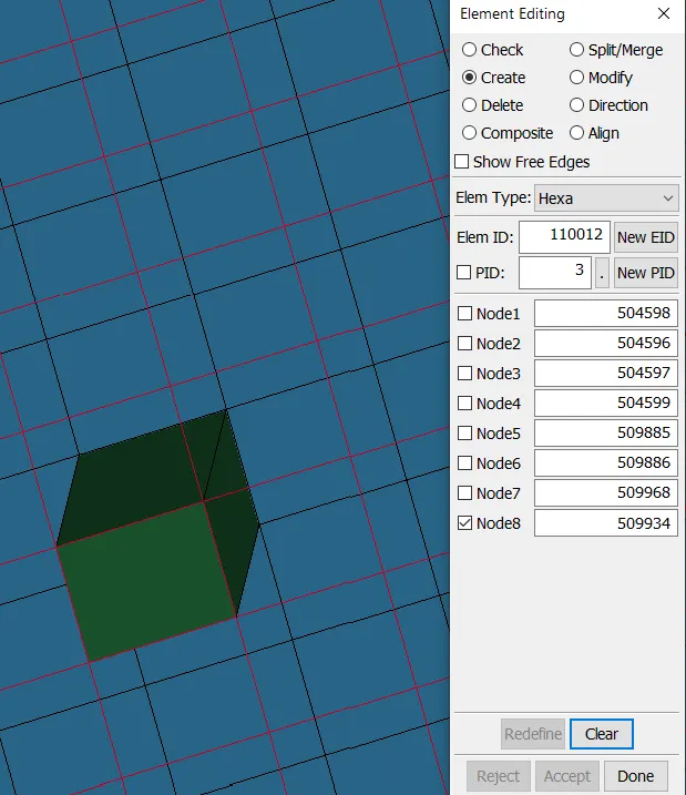
The solid elements are created at the same location where the beam elements are created involving the same nodes. Using the Element Editing option in Element Tools. The Elem Type is set to Hexa and N1-N4 nodes from the upper plate and N5-N8 nodes from the lower plated are selected. The order of selection has to be maintained. Refer to the image below:
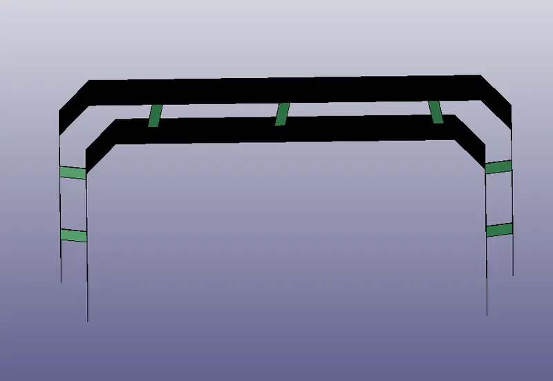
The Hexa element is created at 7 different places as shown below:
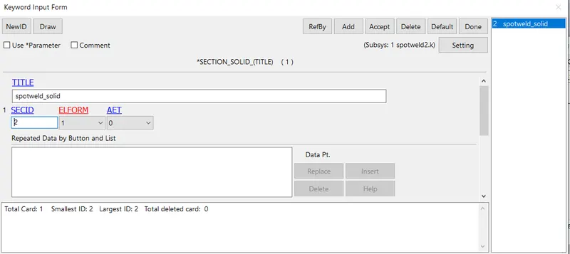
The Solid elements are assigned solid section cards.
The simulation is run with the rest of the cards modeled with the same values as done in beam elements.
Simulation Results:
- Animation
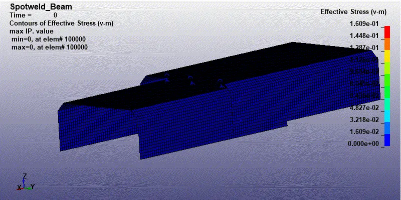
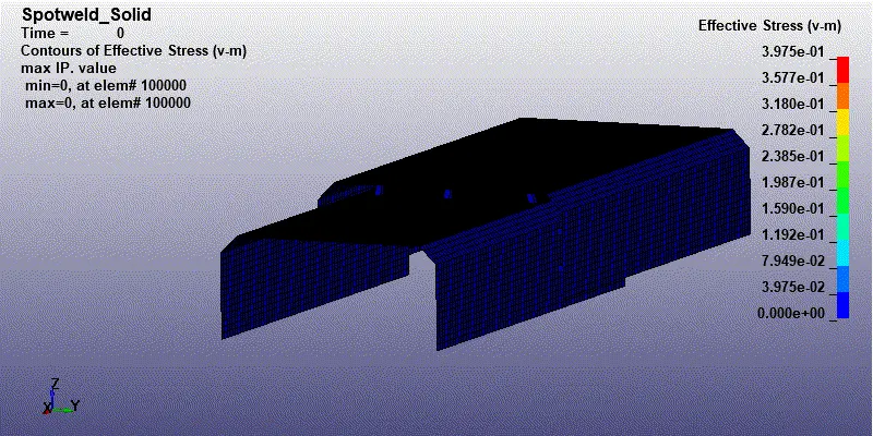
It's quite evident from the animations above that both beam elements and solid elements fail after 1.5ms following the TFAIL value. The von mioses stress in both the simulation vary as both have different element formulation. The max von mioses values for beam and solid are 0.16MPa and 0.39MPa. The solid has more stress than the beam. - Axial Forces:
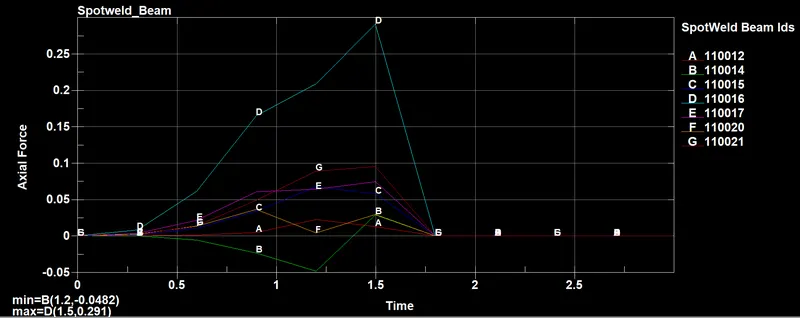
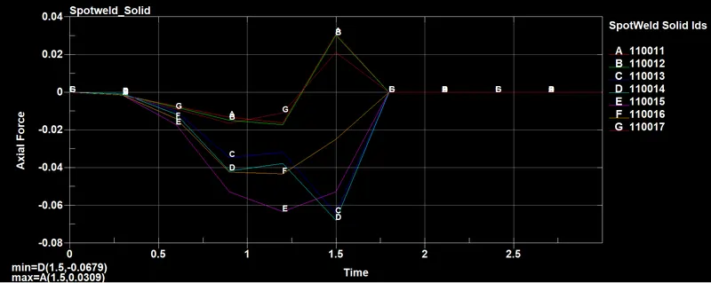
The axial forces at each spot weld vary in both cases some have are negative because the axial force is in the negative direction. In both cases, the max axial force experienced in each spotweld is at time 1.5ms. Since the TFAIL is set at 1.5ms. The axial forces in the beams are higher than in solids. The beam elements experience the force of 50-250N while solids experience 30-60N. - Shear Force
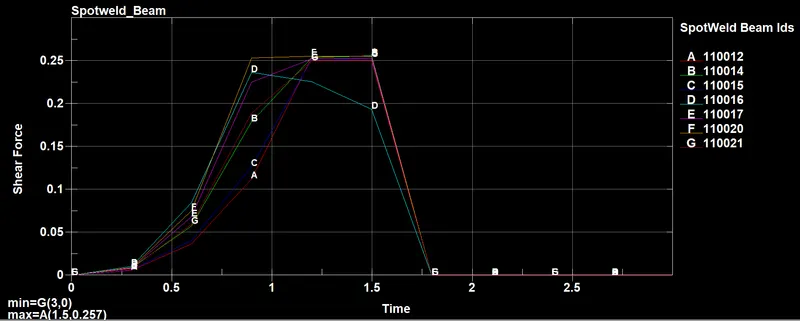
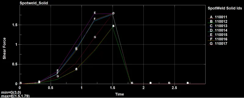
The shear forces at each spot weld vary in both cases some have are negative because the shear force is in the negative direction. In both cases, the max shear force experienced in each spotweld is at time 1.5ms. Since the TFAIL is set at 1.5ms. The shear forces in the beams are lower than in solids. The beam elements experience a force of about 250N while solids experience 1000+N. - Energy Plots
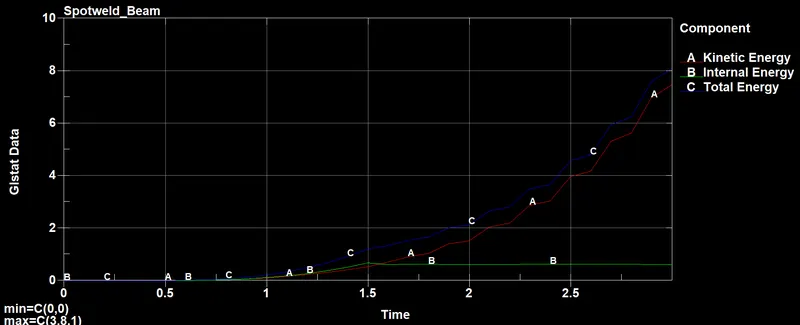
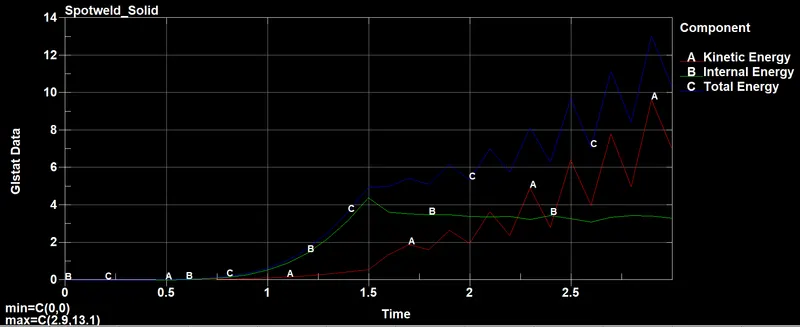
The energy plots are different in both cases because of the type of element formulation used and element type. The solid elements have higher energy values than the beam. The internal energy remains constant post 1.5ms as the elements have failed at 1.5ms. The kinetic energy increases exponentially after 1.5ms, i.e., after the failure of elements.
Conclusion:
- The spot welds fail in both the cases at 1.5ms as the MAT_SPOTWELD card was assigned with a TFAIL value of 1.5. The failure of welds is completely determined by the TFAIL.
- The axial forces are higher in beam elements than in solids, while shear forces are high in solids than beam elements.
- The total energy is high in solids than beams.
With the above points, it can be concluded that solids show more acceptable behavior of a spotweld compared to beams.