Meshing of Door Inner Panel using Hypermesh
Plastic Component 2D Meshing (Side Door Trim) using HyperMesh
The given component was loaded in HyperMesh and the model looks as follows:
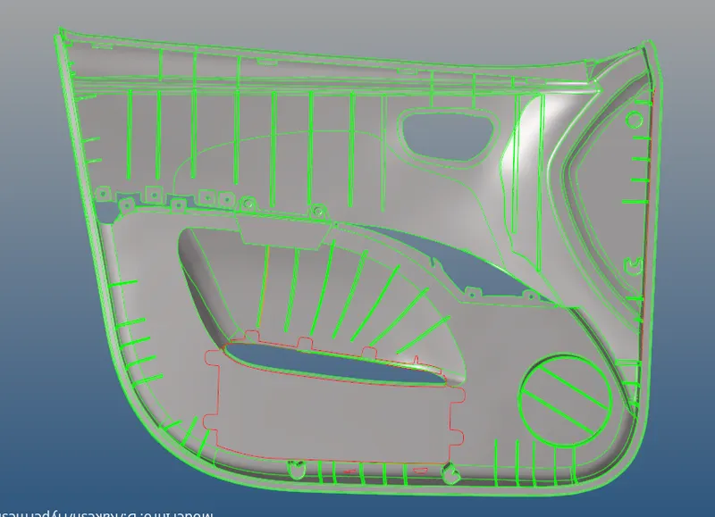
The given model has many geometrical errors like missing faces, free edges. The geometry was cleared before extracting mid-surface.
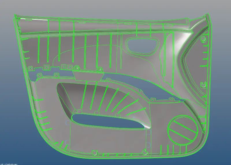
Using Geom tools like quick edit, surface edit the geometrical errors were cleared. The model after clearing errors looks as follows:
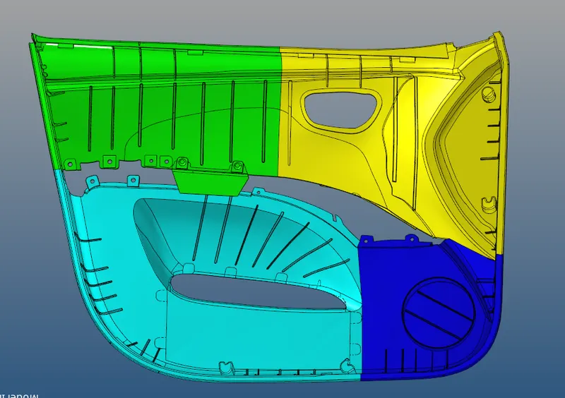
Working on the entire model at one time was tedious, so the given model was divided into 4 components using the surface edit tool. The model after dividing into 4 parts looks as follows:
The mid-surfacing was done using the offset tool as it has varying thickness throughout the geometry. Extraction of the mid surface using auto tools is not possible as all features are not captured properly. Each mid-surface extracted for different thicknesses were assigned their own property cards. The features which had the same or similar thickness were assigned common property card.
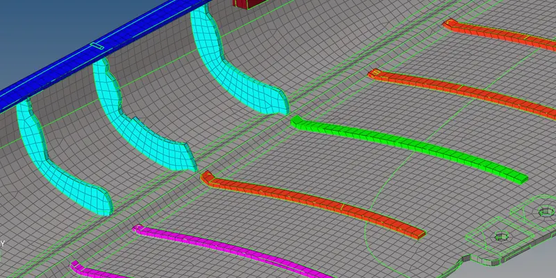
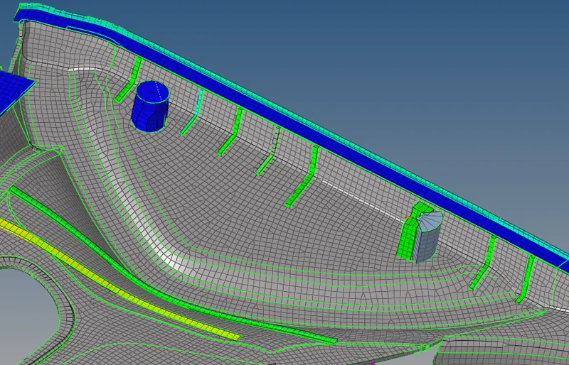
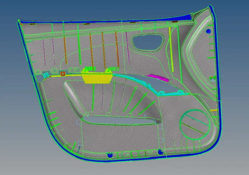
The image below shows components with different properties assigned to ribs, base, and other components:
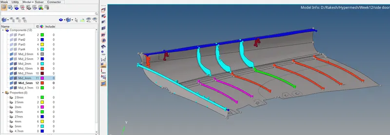
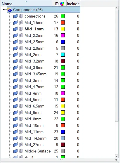
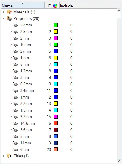
The name of the components was given as per the thickness of a particular component. The images below show the component names and the properties respectively.
The ribs have varying thickness throughout the length, the approach of capturing mid surface of the ribs is as follows:
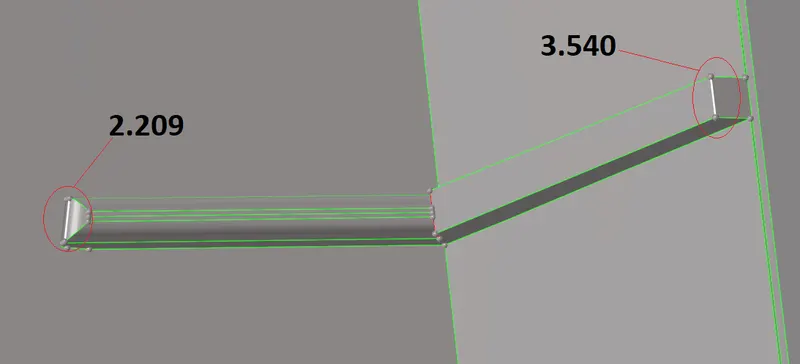
The length of each end of the ribs is checked and the mid surface is given the thickness by averaging both the dimensions. In the given case below the average length would be 2.87mm, so the thickness assigned here would be 2.80mm.
To create a mid surface the midline tool from lines is used as follows:
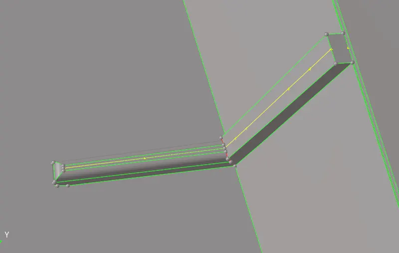
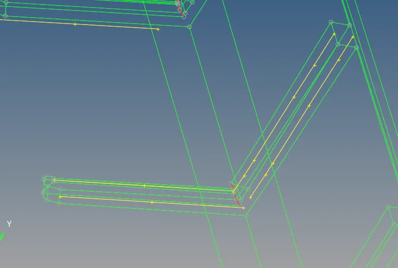
The yellow lines represent the lines created. These lines are converted into surfaces and then extended to the base surface as seen below:
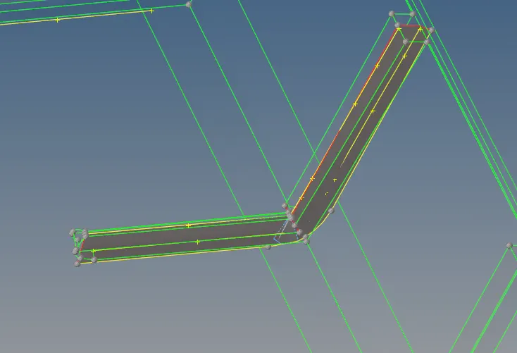
Similarly, for all components with varying thicknesses, the above-described approach was used.
Locators:
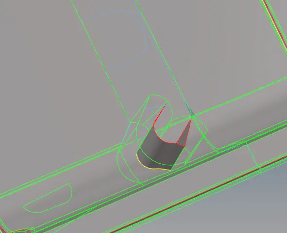
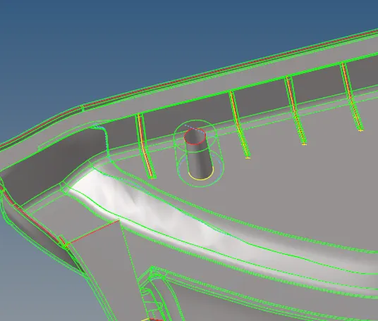
After the mid-surfacing of the entire model, the geometry cleanup was done at certain areas where the mesh flow or elements would fail. The geometry cleanup was done using quick edit tools. The washer split was also created at the holes to have better mesh flow at the holes.
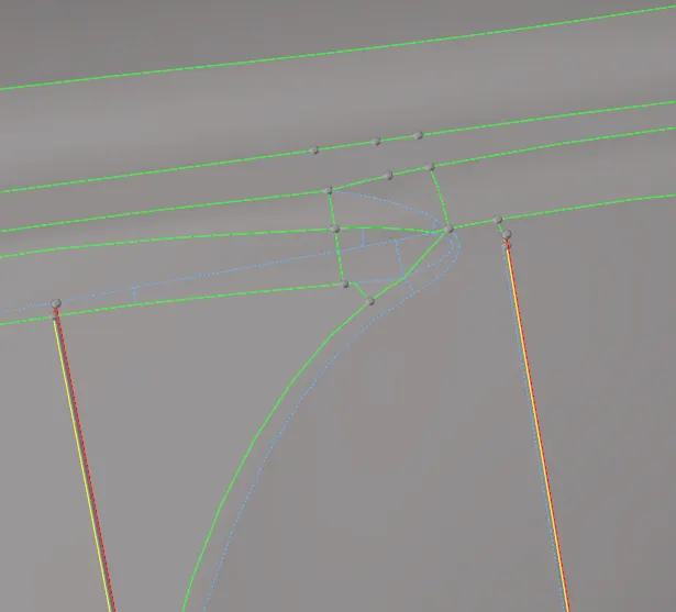
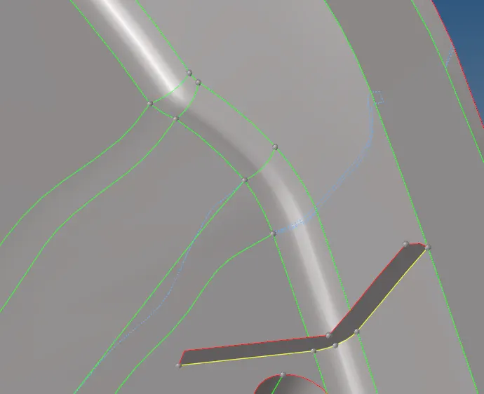
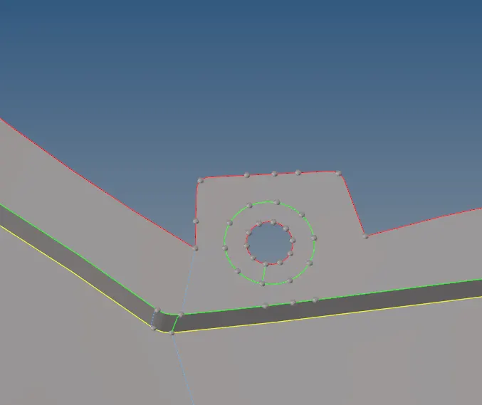
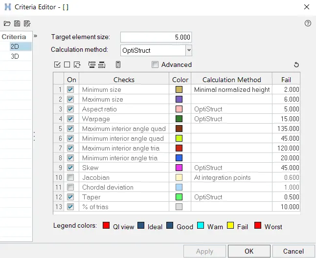
After geometry cleanup, the model was meshed using the automesh tool. Before meshing the quality criteria is set as follows:
The meshing of the components was done individually. For automesh the flow of mesh is not acceptable in certain areas as seen in the image below.
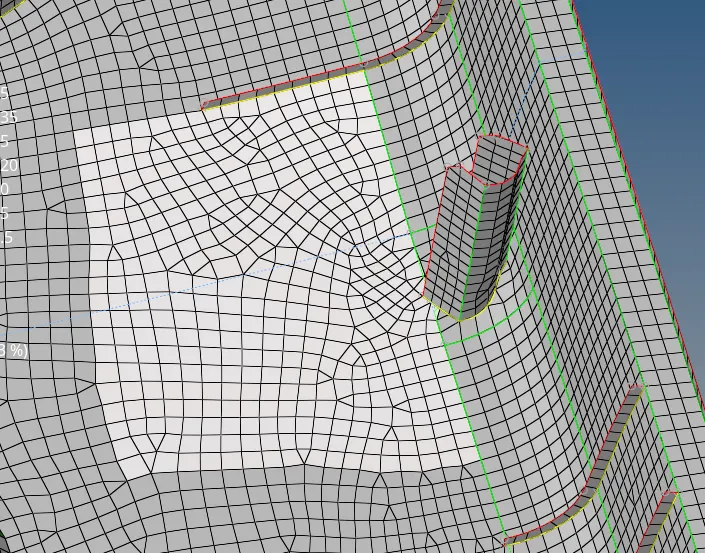
The mesh flow was improved remeshing the areas. Even if the flow is not good enough using the edit element, element rebuild options the mesh flow is improved.
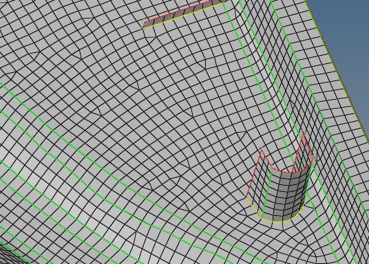
The model is now checked for quality criteria and the elements which failed were remeshed and the mesh quality was optimized.
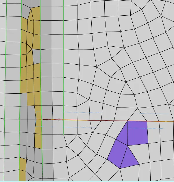
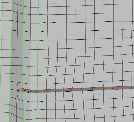
The FE model after clearing all the failed elements and improving the mesh flow looks as follows:
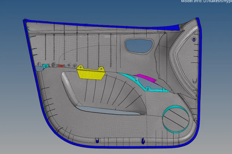
The following component below is not connected to the main model. The model is to be connected using bolts or rivets to the main body.
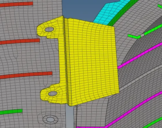
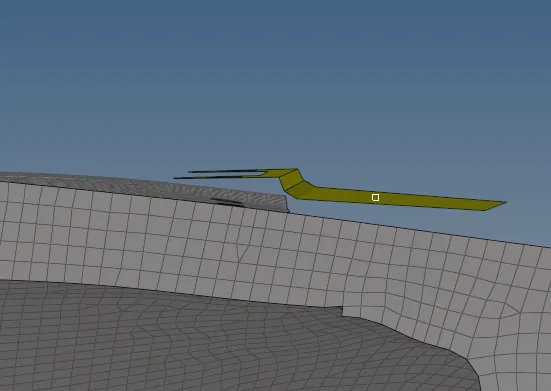
The clarity on the connection to formed is not given so the component is connected using just RBE2 rigids.
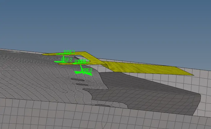
The FE model is as follows:
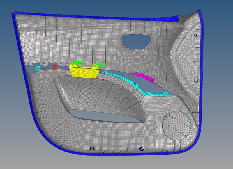
2D Detailed element representation