Extraction of Mid-Surface and Meshing of Sheet Metal Component using ANSA
When the given model was viewed in ANSA software following points were observed:
- The model was imported and geometry consists of a number of errors.
- Hard to visually find the numbers of part present in the model itself.
- Hard to understand the actual shape of some features as it was imported from another workbench (software).

Steps
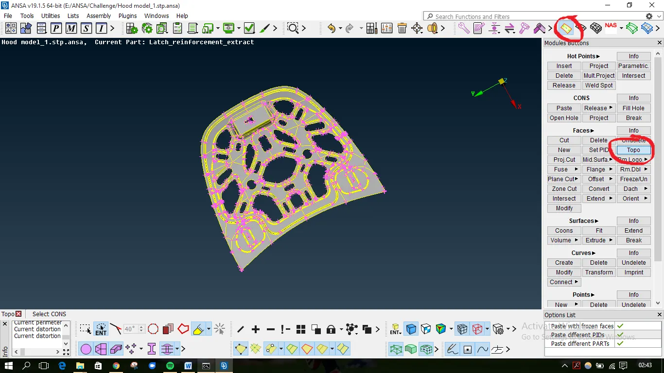
1) After importing model topo(Topology) was performed using the option in Topo module in Face section. The topo just eliminates the unnecessary geometrical distortion in the model.
2) The second important thing is to identify how many parts are in the assembly/model. By checking the properties of geometry we can get the idea about the number of parts in the assembly. By hiding and extracting them in isolated views the parts/geometries that are hidden between to parts is separated.
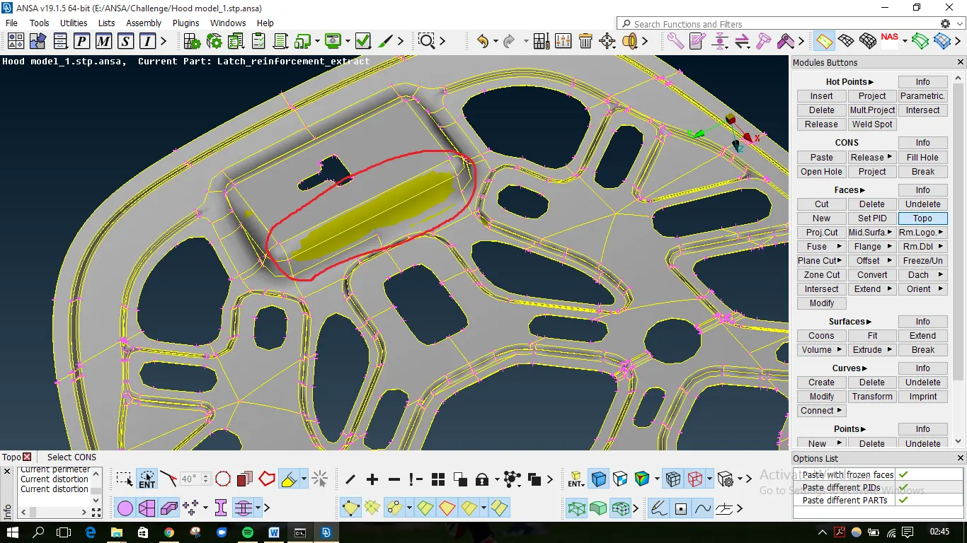
here as you can see the latch is in-between the outer and inner body its hard to identify by just seeing it in some complex geometry.
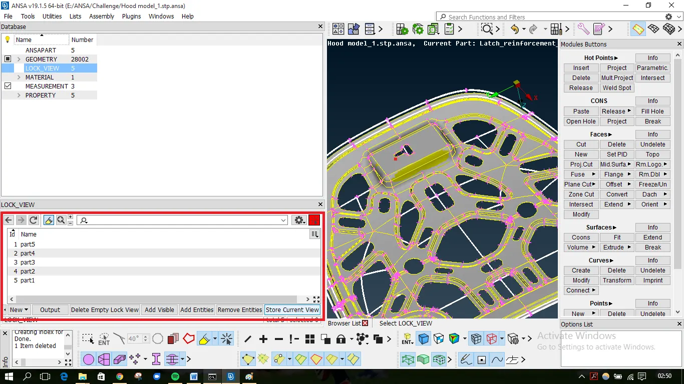
The extracted parts in different views were saved in the lock views. It can be managed accordingly by accessing the lock view in the database. For easy understanding, the parts were renamed as follows
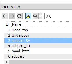
The subpart_RH and subpart_LH were similar so they were stored in new lock view under the name subpart
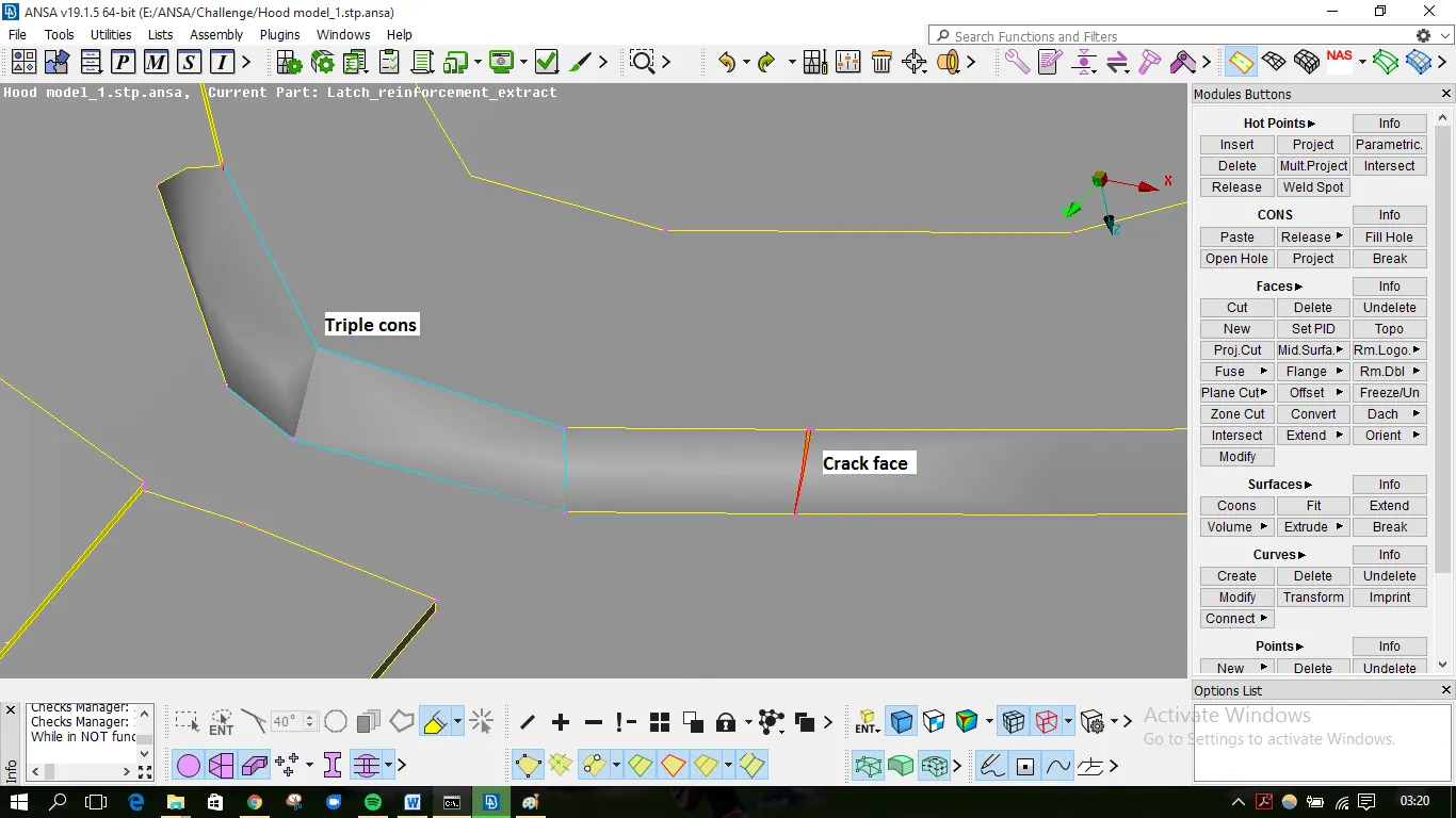
3) The lock views created for each part were worked on separately. The parts were 1st checked for geometrical errors like crack and triple cons.
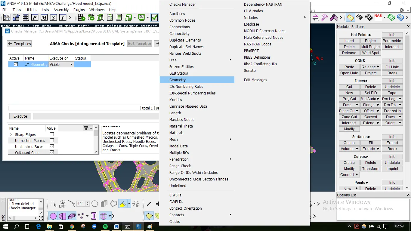
The geometry check was run and errors were highlighted.

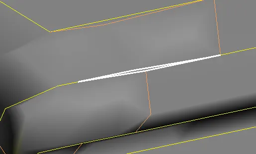
4) The particular error is located by right-clicking on the error and choosing "show only" option. After that, the neighbouring elements were called. For triple cons, release the con and perform topo. For crack surfaces, a new face is generated and for needle faces the either of the two geometrical lines is removed. Most of the errors can be fixed using auto-fix option.
Needle Faces
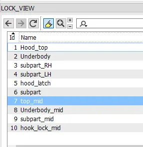
5)Extraction of mid surface: The mid surface was extracted by Manual mid surfacing(Offset) method. Before offseting the thickness was measured for each part and accordingly the offset was done. Mid surfaces were stored in new lock views as follows
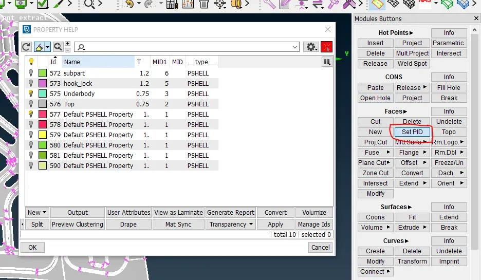
6) Next thing after creating mid surface was the main operation that is meshing. But before that, the PID has to be set up for each the mid surface with a thickness of the respective part. The PIDs were given same name was that of the part name mentioned in lock view to avoid confusions and colours were also chosen.
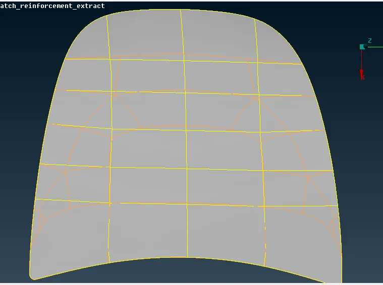
7)Before getting into the mesh module the mid surface was performed with Topo and check geometry was run to make sure the model to error-free. And to have better mesh flow some geometrical changes were done. The orange lines show construction lines while they were eliminated and new cut lines were created shown in yellow lines. The care was taken the geometry was not compromised in the process.
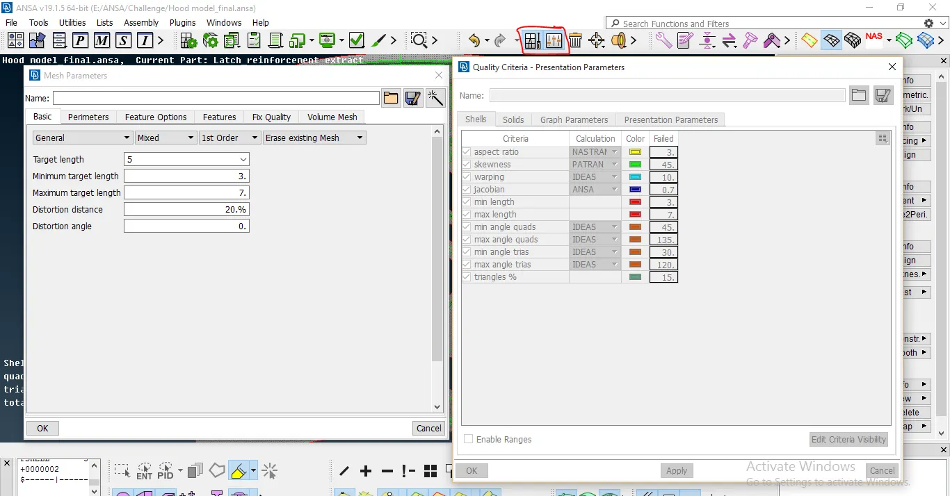
8)The mesh criteria and quality criteria were defined as given in the challenge.
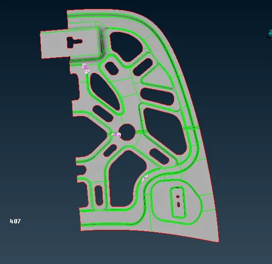
9) For symmetrical parts i.e., Top and Underbody only half of the geometry was used for meshing and other halves were deleted.
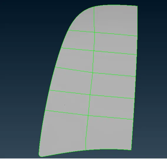
10) The distance between the 2 adjacent nodes was set to 5 using the length parameters option. This would allow the mesh elements to achieve the Targeted length as per the criteria.
11) For meshing the geometry BEST mesh option was used. For editing the or restructuring the mesh and its flow these options were used; Reconstruct, smooth, Split, swap, num+/-, Init, slide, Mark/Unmark, move, MV point some time Erase to repair and make mesh flow more smoothly.
Errors During Meshing and Solutions.
1) The mesh was performed with any changes being made to the predefined lines(construction lines), the flow of mesh was bad.
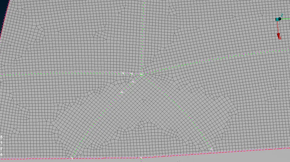
But when new cuts were introduced as mentioned in step 7, the flow was better.
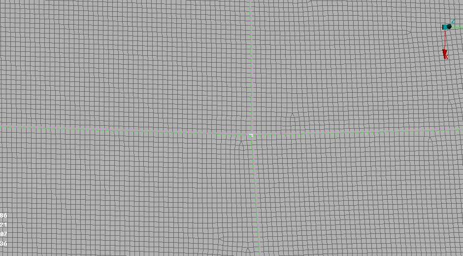
2)In some cases near the features, there are extra construction lines to defined the feature. That may cause fail the element/feature for the Quality criteria.
As the Quality criteria which was defined with the Target length of 5 mm along with Min to Max limit 3 to 7mm respectively.
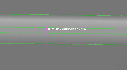
The hatch surface had a length of 2 which is much lesser than our define length with including its limit, it was decided to eliminate one line from hatch surface. In this way some feature shape were compromised.
3)Some unnecessary hot points were left out after defeaturing in geometry. Those have to be eliminated as it may fail a particular element.
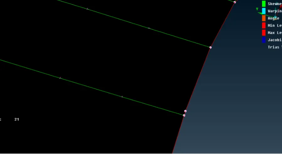
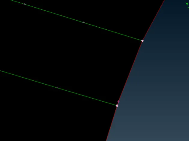
here are some examples of defeaturing
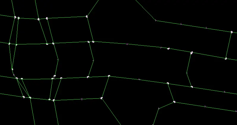
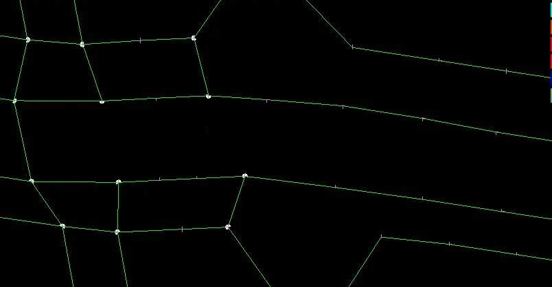
This feature below fails as the 2 lines coincide at 1 point.
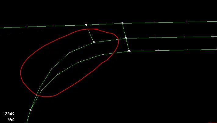
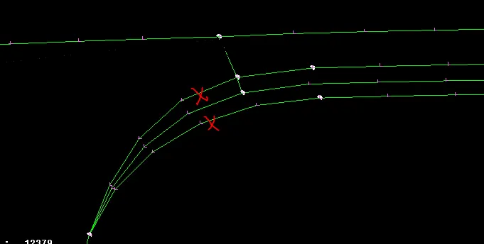
Here the best option to catch the feature geometry is by usingx Datch option from topo module which will create a centre line along the feature. The 2 lines cross marked are removed and the new centre line maintains the feature.
Quality Failure
1) During the meshing, some quality issues were faced, one of them is due to Hem bend at the end of the Top extract along the edge. This Hem bend is failing for minimum length issue since it was an important feature, it can not be eliminated by defeaturing. If the quality criteria are reduced the issue is fixed, but was not allowed to change the criteria, so it was left as it it.
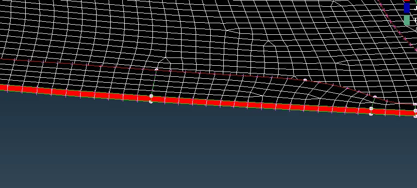
2)Failing for maximum length and jocobian
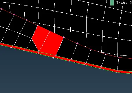
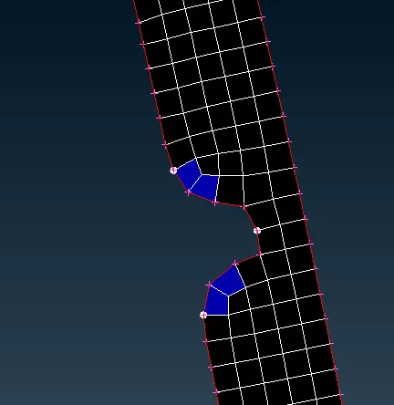
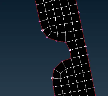
Fixed using Reconstruction option.
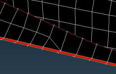
Converting the mid surface into Solid
Apply thickness to the mesh part by checking the Draw shell as solid option in Quality Criteria window.