Side Crash Analysis of Car using HyperCrash and RADIOSS
Aim: To analyze the side impact on the vehicle using HyperCrash and RADIOSS.
Objective:
- To set up the pre-processed FEA model in HyperCrash to recommended parameters in property cards and engine files
- To analyze how the deformation takes place when the vehicle experience a side crash.
- To compare the Sectional force in the cross members.
- To record the intrusion at critical points in the vehicle.
- To measure the peak velocity of the inner node of the door.
Theory:
Crashworthiness:
First used in the aerospace industry in the early 1950s, the term “crashworthiness” provided a measure of the ability of a structure and any of its components to protect the occupants in survivable crashes. Similarly, in the automotive industry, crashworthiness connotes a measure of the vehicle’s structural ability to plastically deform and yet maintain a sufficient survival space for its occupants in crashes involving reasonable deceleration loads. Restraint systems and occupant packaging can provide additional protection to reduce severe injuries and fatalities. Crashworthiness evaluation is ascertained by a combination of tests and analytical methods. One of such tests includes Side Crash.
Side Crash
Side crash of a vehicle can occur by the collision of two moving cars in right angles to each other or hit a rigid body like pole while the car is motion. The point of impact, in this case, is in very close proximity to the passenger compared to any other crash. The car structure at the side must be reinforced with a metal structure that can absorb maximum energy before it is transferred to the interior part of the car and the person experiences the least amount of shock and keep the person safe.
The durable body form including the center pillar (B pillar), rockers, and floor cross rockers, etc., helps protect passenger space and helping to reduce damage from a collision. Impact Absorption and Load Dispersion is shown in the image below.
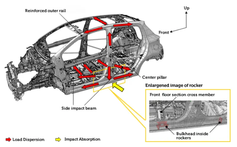
Deformation of the vehicle can be reduced during the side collision by enlarging the locker panel and the center pillar, as well as strengthening the door lock area. Additionally, the intrusion rate of the doors being pushed into the cabin will be reduced and the impact of the collision will be distributed and absorbed effectively.
Preparations of Car For Crash Analysis using HyperCrash
The unit system of the model is checked by opening the starter file in the notepad and it is as follows:

The unit system is in [Kg mm ms].
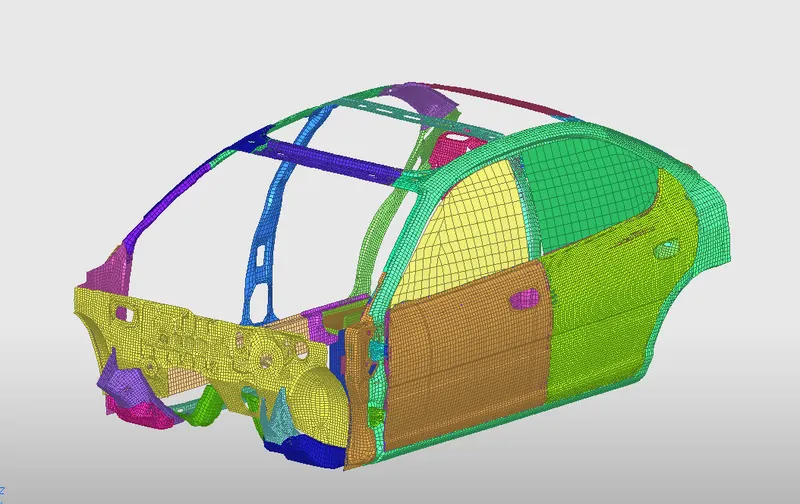
The software used for this simulation is a student version, so the complete FE model with a high volume of elements is not supported. To overcome this problem only part of the model i.e., the cabin structure of the car with only one side with doors is used for simulation.
The model is loaded in the HyperCrash. The FE model of the Frontal structure is as follows:
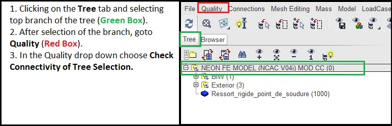
The model is checked for connectivity before applying any recommended parameters as follows:
The result of the quality check for connectivity shows (image below), 3 free parts are shown as below:
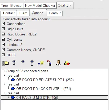
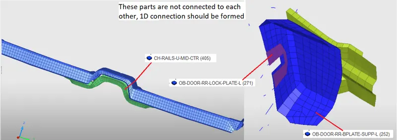
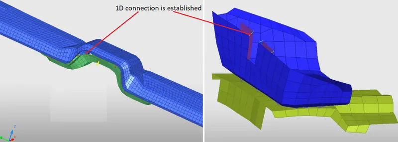
Using the same properties 1D connection is defined for these parts and is as follows:
The model contact interface is checked and is found as below:
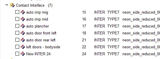
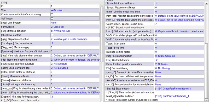
The contact interfaces available are not really useful for this particular simulation and the entire model should be in self contact. So the current contact interfaces were deleted and a new self contact interface was created with TYPE7, friction 0.2, and recommended parameters.
The model with the self contact interface TYPE7.
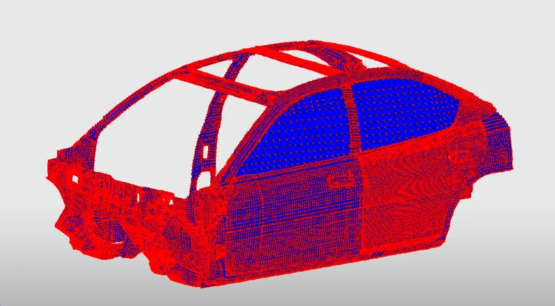
TYPE7 parameters:
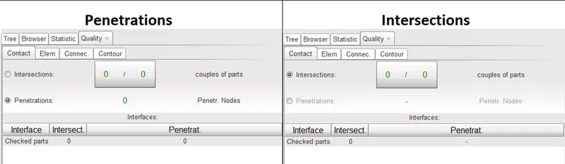
Quality check for penetrations and intersection after the contact interface is applied.
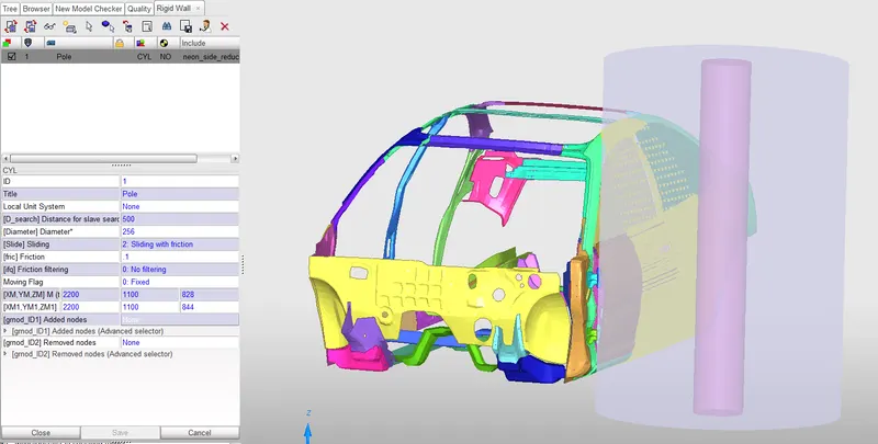
Creation of RIGID WALL/POLE
The rigid pole is created with sliding friction of 0.1. The search distance is the area under which the slave nodes are captured for the impact. The search distance is 500, the shaded box in the image below shows, the area covered in that distance and the yellow color represents slave nodes in that search distance.
The COG of the model is as shown below:
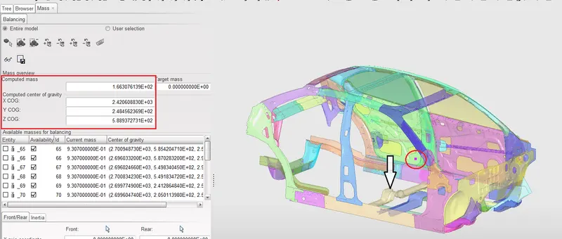
The red box shows the coordinates of the CG and the dot in the red circle shows the CG point of the model. It is not at the appropriate location of the CG of the vehicle. The location is shown with an arrow in the above image, CG is can be nearby to that location. To achieve that mass is added on the rear side of the model. The target mass is 700kg.
The mass added is shown below and the target mass is achieved:
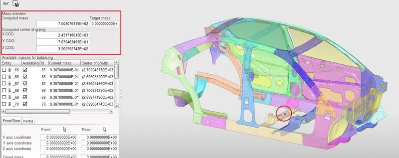
The red circle shows the CG of the model at the right location and its coordinates are given in the red box.
Applying Initial velocity to the model
The model is given an initial velocity of 30kmph (8.33333mps). The entire model is selected to apply the velocity in the y-direction as the vehicle approaches the rigid wall in the y-direction.
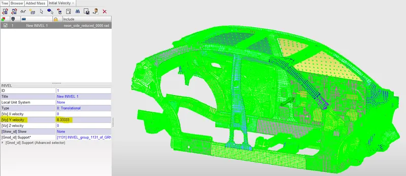
Applying Timestep and Run time
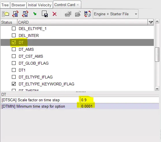
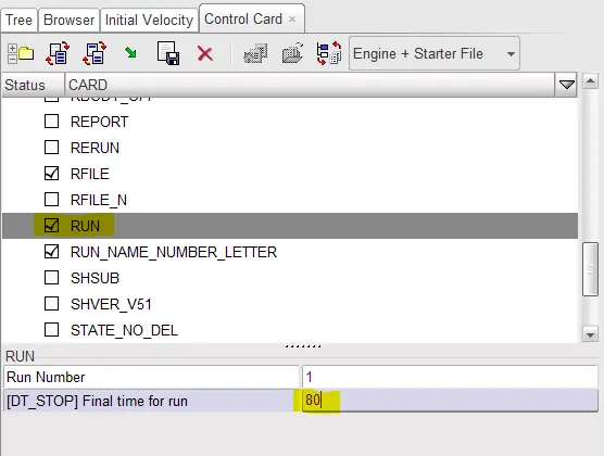
The timestep of 0.1 microseconds is applied by adding the DT card in the engine file which available in the Control Card tab. The scale factor is 0.9 (shown below in image 1). The run time is set at 80 microseconds in the RUN card in the engine file (shown below in image 2).
Output Requests:
1. Sectional force in the cross member
To determine the sectional force, the section is created at a particular location on the cross member which has the normal same as the rigid wall.
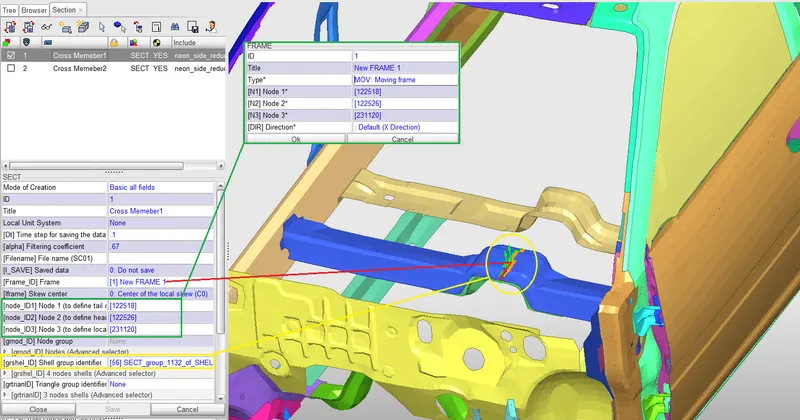
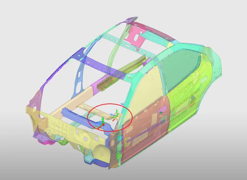
The red line shows the Frame which is used for reference for the section at the cross member and has its normal away from the pole. The shell elements involved in the section are shown with the yellow circle. The nodes determining the XY plane are the same as that of the frame (green boxes). Similarly on the other cross member section is taken.
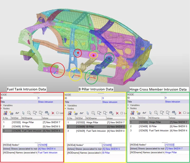
Intrusion at B pillar, hinge pillar, and fuel tank region
The intrusion of the nodes can be measured using the TH of Nodes option under the Time History menu in the Data History tab. The variables to be measured here is kept DEF as it has all the vectors inclusive. Follow the image below for details related to intrusion.
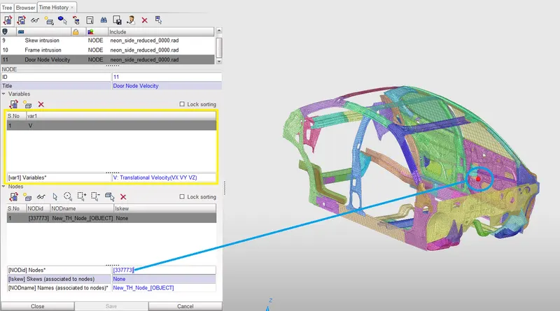
Peak Velocity of the inner node of the door
The peak velocity can be found out for a particular node by the same method that was used in previous intrusions. The variables for which time history is required is chosen in the Variables dropdown. In this case, only translation velocity is required, therefore only variable V is used (refer image below).
After setting up all the output data required for the simulation, the model quality is checked.
Model Check
The model quality is checked using Model Checker in Quality Tab.
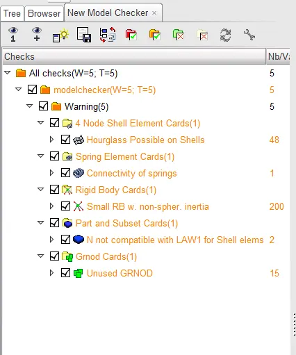
The quality check shows no errors only warnings. The model is good to run for simulation. The file is exported and run for simulation in RADIOSS.
Simulation Results:
Animation of the crash simulation is as follows:
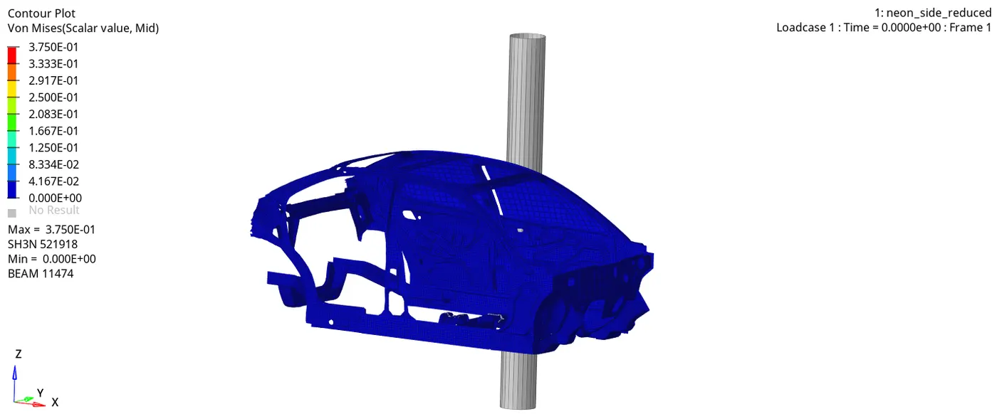
The Von-Mises stress experienced maximum by the model is 37.5GPa at shell 521918.
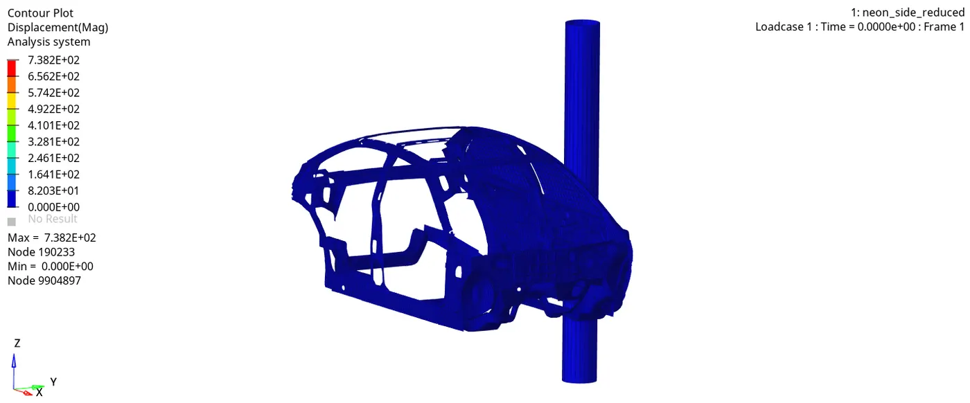
The maximum displacement is 738.2mm by node 190233.
Sectional Forces:
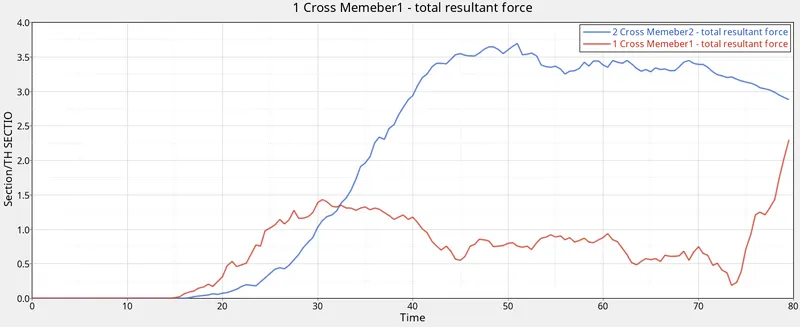
The sectional force is measured at the section created on the cross members. It is observed that both the curves at zero for about 15ms and then gradually start increasing, it's due to impact the forces are transferred over the cross members after the impact at 15ms. Cross member 2 is under the B pillars so it experiences more forces than the other cross member.
Intrusions at B pillar, hinge pillar, and fuel tank region
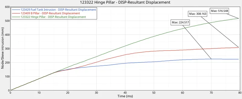
The max displacement is observed in the node at the hinge pillar of about 516.548mm. Fuel Tank node is displaced least as that node lies farthest most from the impact region among the three nodes. Even though the B pillar node is closest to the impact region displacement is less than the hinge pillar because most of the energy is observed by the B pillar which transfers less amount of force on the rocker base of the B pillar. This shows how critically important the B pillar is in side impact/crash.
The intrusions at the fuel tank region can be reduced by having a robust reinforcement similar to the B pillar which would absorb most of the impact energy.
Peak Velocity of the inner node of the door
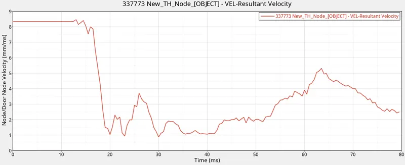
The velocity of the node before impact would same as the user-defined initial velocity i.e., 8.33m/s. After 10ms the impact takes place and the node starts moving in the direction opposite to the initial velocity, this explains a sudden drop in the velocity. The velocity will drop to 1m/s meaning 7.33m/s in the negative direction. As the simulation propagates the node undergoes displacement in different directions due to the deformation of the vehicle, this justifies the variation in velocity after 20ms.
Energy Plot
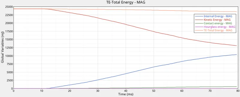
The internal energy and the kinetic energy curves are mirror images of each other. It is because the internal is gain during deformation is from the kinetic energy and conserve the energies. But it's seen that there is a drop in energy as the simulation progress, this is because of the loss of energy in the form of contact energy. The gain in contact energy is the same as the loss in total energy. The deformation increases the intersection of the shell elements and to avoid the intersection the contact energy is absorbed by the nodes which move out of the intersected shell. The hourglass energy is zero because of the shell formulation used in the model. QEPH shell formulation is used in this model which eliminates the hourglass effect in the shells during deformation.
Conclusion:
- The simulation results are not that accurate because the complete model is missing, but it gives a brief idea of how the impact affects the vehicle at critical locations.
- After studying the simulation results it can be concluded that the B pillar is a very critical part of the vehicle when the vehicle experiences side impact. The B pillar must be strong enough to withstand the impact force and at the same time ensure the safety of the passenger with very least injury chances through shocks.
- The cross members ensure that the cabin is not crushed and the must be reinforced to a level where the damage can be controlled and improve vehicle stability.
- The intrusions on the rocker beam also highlight the importance of the rocker beam in ensuring the stability of the vehicle.
- The fuel tank intrusions can be reduced by increasing the reinforcements in that area.