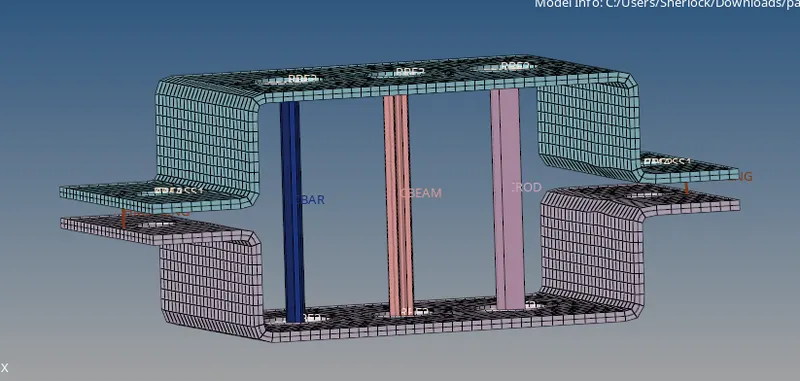
1D Connectors (beams/ bars) using HyperBeam
1D Connection using HyperMesh
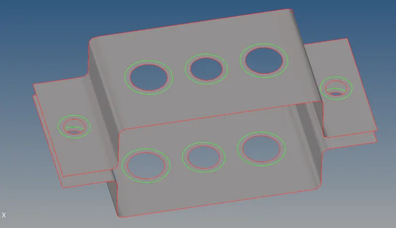
Given model was loaded in HyperMesh and the model looks as follows:
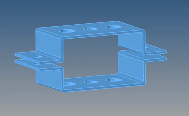
The model does not have any geometrical errors and good to go for mid-surface.
Using the auto midsurface option the mid surface was extracted. and the mid surface looks as follows:
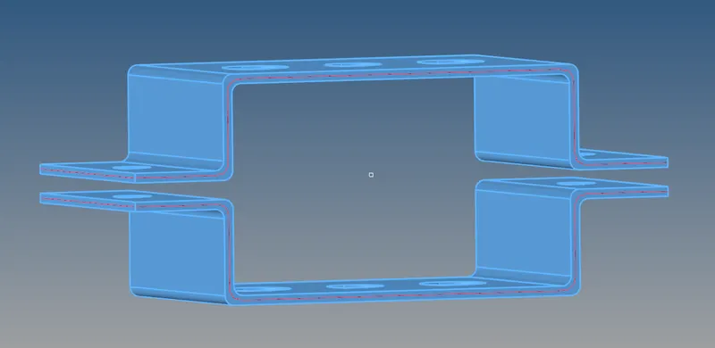
It's seen that the auto mid surface worked fine and the parent geometry is deleted as it's no longer useful. The holes of the brackets are given washer split to have better mesh flow. The mesh size is 5, so the offset value assigned here is 5 (see image below).
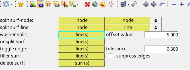
The model with washer split is seen as follows:
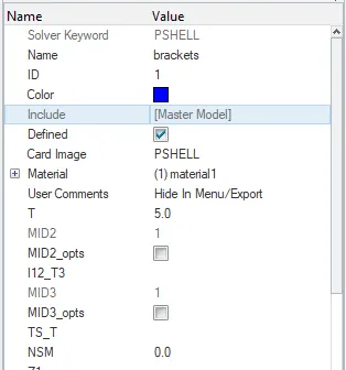
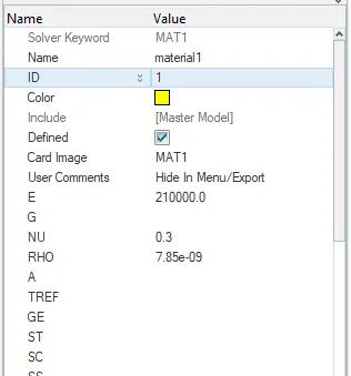
The property card and material card are created for both the brackets and the thickness of 5mm is given it. The image below shows the property card and material card.
The model is ready for 2D meshing, before starting the meshing the quality criteria is set in elem tab of the 2D module using edit criteria as follows:
2D--> elem cleanup-->edit criteria...
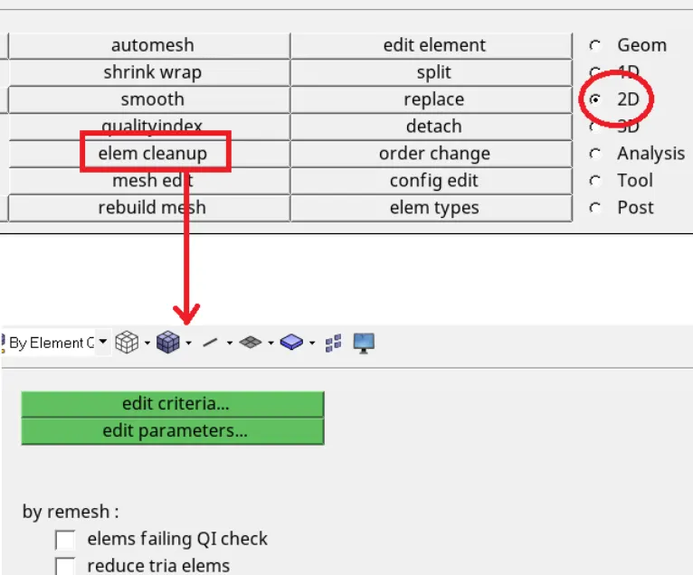
After clicking the edit criteria a window pops up shown below and the given criteria values are entered and applied.
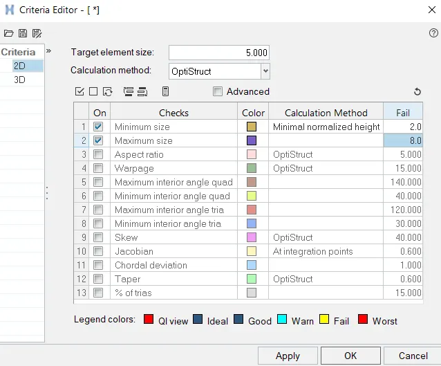
The mesh size is set to 5 in automesh option.

The meshing is started from complicated features in the geometry. In this model, the hole areas are a complex part, so 1st meshing is done at this area. The meshed washer area looks as follows:
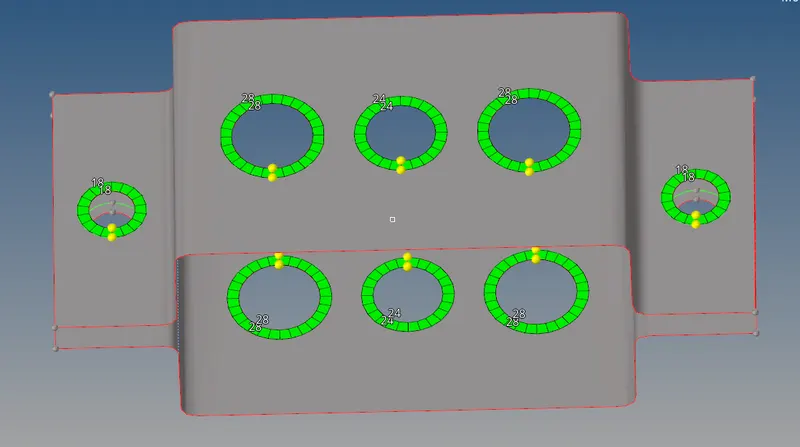
Since both the brackets are the same so only 1 bracket is meshed and elements are reflected to the other bracket. The complete mesh of 1st bracket is as follows:
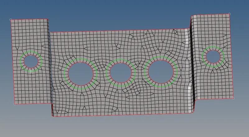
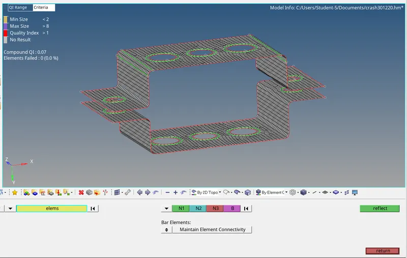
It is seen that the mesh flow is not in good shape. This is improved using the quality index tools and better flow is achieved by eliminating trias and repetitive remeshing of elements. The image below shows improved mesh.
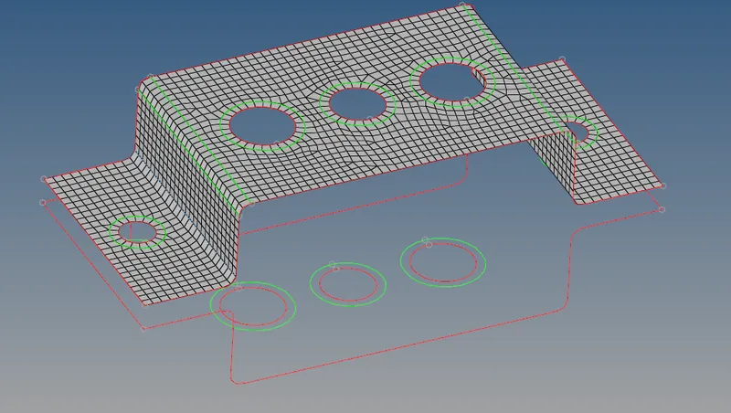
Now the elements are reflected to the other bracket by using reflect option in the Tool tab. The image below shows reflected elements on the 2nd bracket.
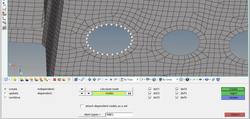
The holes are given rigid connections in the form of RBE2 and RBE3. As per the requirement
*the hole which is to be connected with the 1D rod element is given RBE2 connection with all DOF constrained.
*the 2nd hole is given RBE3 connection with all DOF constrained.
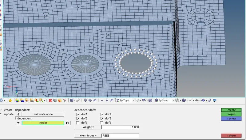
*the 3rd hole is given RBE3 connection with only XY DOF constrained.
The image below shows the RBE2 connection with all DOF constrainted.
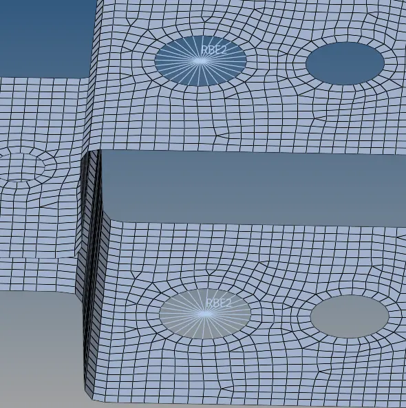
The similarly RBE3 connections are formed and the image below shows RBE3 for the 3rd hole with XY DOF constrained.
Using the HyperBeam option the rod, beam, and bar cross-section are defined as follows:
a. Rod element:-
Cross-Section: BOX- Dimension a= 12 mm
dimension b=10 mm
Thickness t= 0.75 m
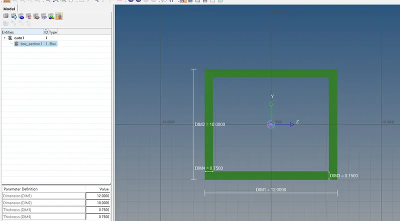
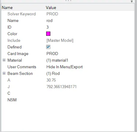
The property card for the rod is created with card image as PROD and is as follows:
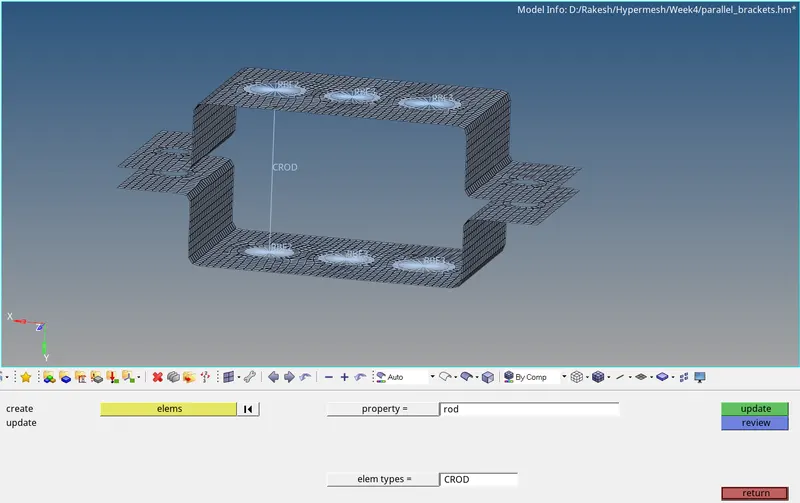
The rod is realized using the rods option in the 1D tool tab as follows:
b. Beam element:-
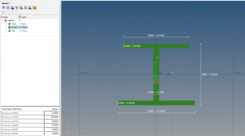
Cross-Section: I Section- Dimension a= 8 mm
Dimension b= 10 mm
Dimension c= 8.5 mm
Thickness t1= 0.75 mm
Thickness t2= .6 mm
Thickness t3= .6 mm
The cross-section for the beam is defined in HyperBeam as follows:
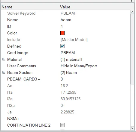
The property card for the rod is created with card image as PBEAM and is as follows:
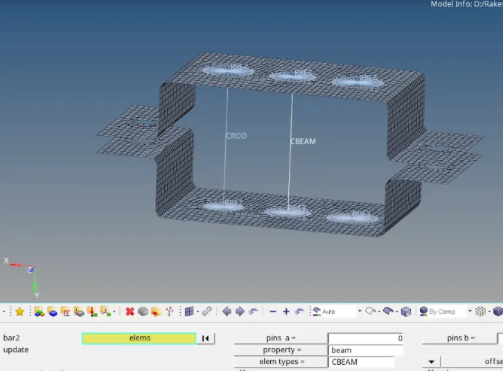
The beam is realized using the bars option in the 1D tool tab as follows:
c. Bar element:
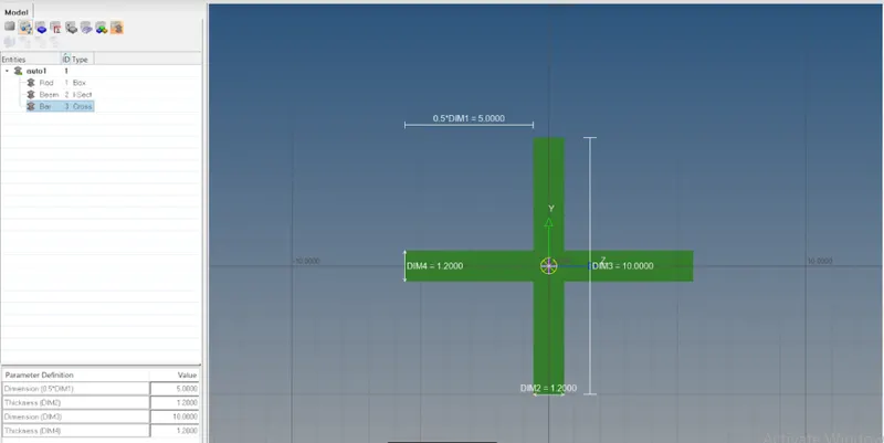
Cross-section: X section- Dimension DIM1= 5 mm
Thickness DIM2= 1.2 mm
Dimension DIM3= 10 mm
Thickness DIM4= 1.2mm
The cross-section for the bar is defined in HyperBeam as follows:
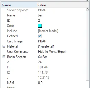
The property card for the rod is created with card image as PBAR and is as follows:
The bar is realized using the bars option in the 1D tool tab as follows:
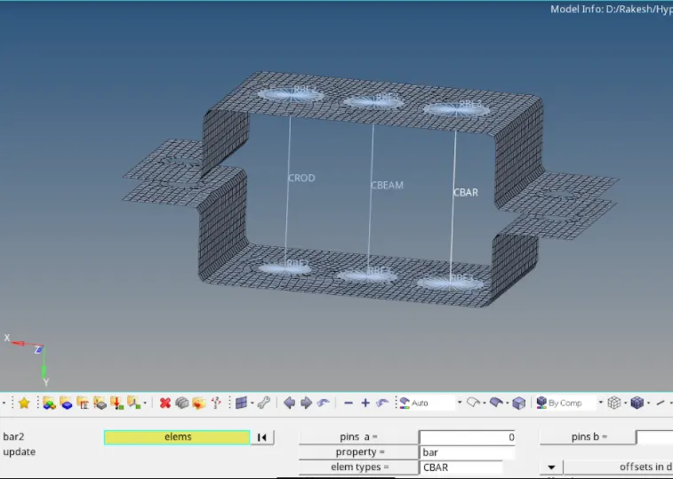
Creation of Mass
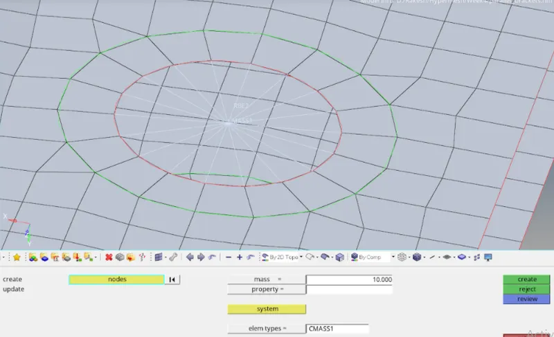
The RBE2 link is created at the top bracket holes on the flange. The mass of 10 is added to the master node of those RBE2 links using the masses option in the 1D tool tab as follows:
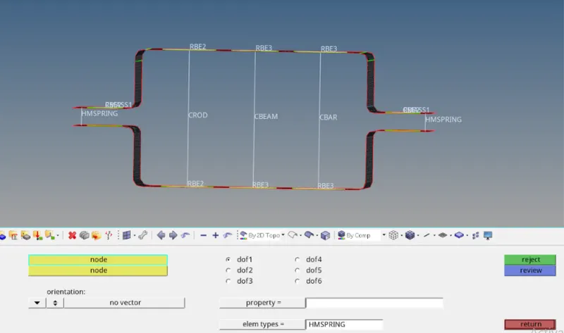
The two brackets are connected to each other by creating a spring connection using the springs option in the 1D tool by selecting random nodes on both the flangs of the brackets as follows:
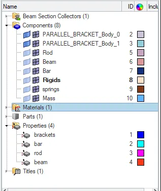
Using organize option in the Tool tab, all the 1D elements are move as per the component created to assign them.
The cross-section of 1D elements can be view by changing the 1D element representation from traditional to detailed representation and the same is done for 2D elements too. The view is as follows: