Roof Crash analysis of Dodge Neon car with an impactor using RADIOSS solver.
Aim: Roof Crash analysis of Dodge Neon car with an impactor using RADIOSS solver.
Objective:
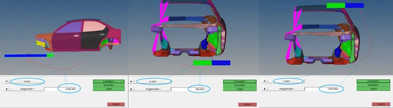
- To place the impactor at global coordinate ( -3500.00, 584.822, 1343.06).
- To create a TPYE7 contact interface between impactor and vehicle coefficient of friction to 0.2.
- To create appropriate rigid bodies and apply boundary conditions to the vehicle and impactor.
- To impose the velocity of the impactor starting from 0 mm/s at t = 0. The displacement of the impactor should be 200 mm @ 200 ms.
- To create control cards and engine files required for simulation.
- To check that the FMVSS 216 target load of 47,000 N (= 3 * GVW) has been met.
- To plot the energy vs. time curves.
Roof Impact Test
The stronger the roof better it can protect the occupant. A vehicle roof must be able to handle a load of one and half times its weight. The Roof Impact type of simulation is considered as Quasi-Static Analysis means the Car body is stationary and the Impactor is in motion.
By doing the roof impact test the strength requirement for a passenger car roof can be determined. The vehicle roof and its supporting structure must be strong enough to withstand the load exerted by the impactor.
US Federal Motor Vehicle Safety Standard (FMVSS) 216, are applicable for Roof Crush Resistance of a Passenger Cars. This standard establishes strength requirements for the roof of passenger cars and is intended to reduce deaths and injuries resulting from the crushing of the roof into the passenger compartment. This standard and procedure are mostly applicable for a vehicle of GVWR 2722 kg or less. For this simulation, the obtained through simulation is compared with 3 times the GVW value. The door and windows are kept completely closed during the simulation.
Procedure
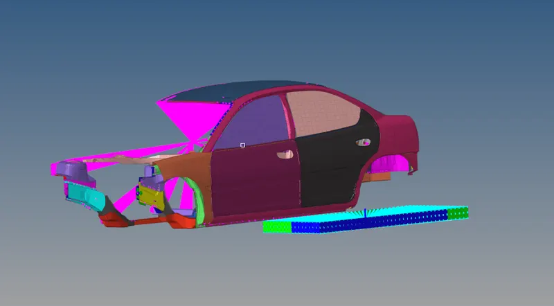
The neon roof starter file is loaded in HyperMesh. The impactor starter file is also loaded to the same session in HyperMesh. The models look as follows:
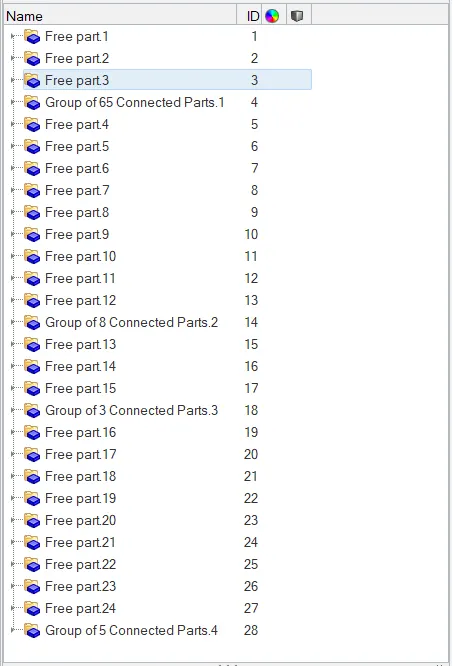
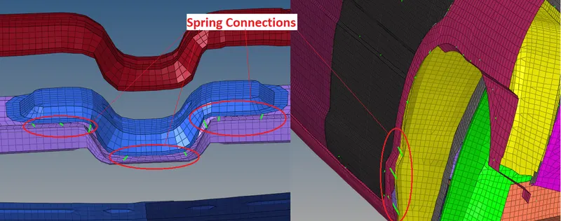
The entire model is checked for connectivity and free parts are identified using the Find COnnectivity tool. There are 24 free parts to be connected to the rest of the model and the free parts are as follows:
The connection is formed by introducing the spring at the appropriate locations in the free part and the rest of the group. The spring properties are as follows:
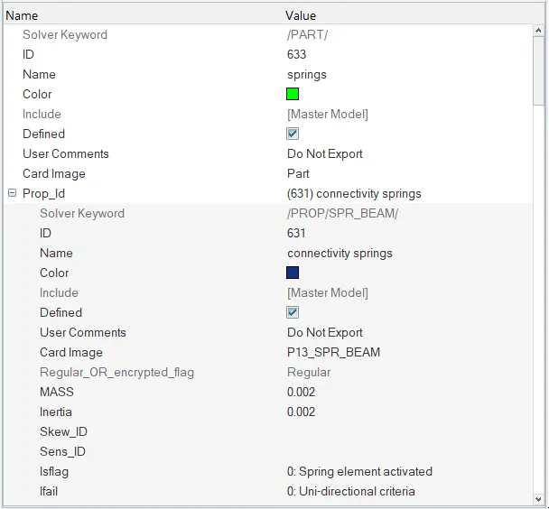
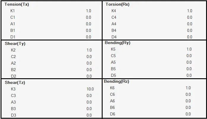
Spring Connections:
The impactor is moved to the roof of the vehicle to the coordinates (-3500.00, 584.822, 1343.06) by translate tool. All the nodes of the impactor are selected and translate as follows:
The rotation of the impactor as shown below:
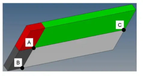
A 180° rotation about the global z-axis with the point opposite to C as the base point. A 5° rotation about the axis through axis AB. A 25° rotation about the axis through axis AC.
Using the rotate tool the above position can be achieved.
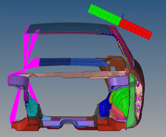
COG of the Vehicle
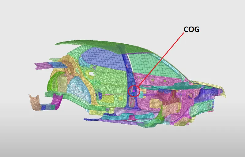
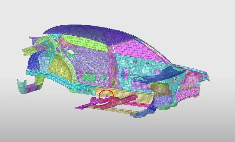
The COG has to be near the belly pan, the extra mass is added to the cross beams and COG is moved down in z-direction as follows. The total mass is set to 700kg after added extra mass.
Interfaces
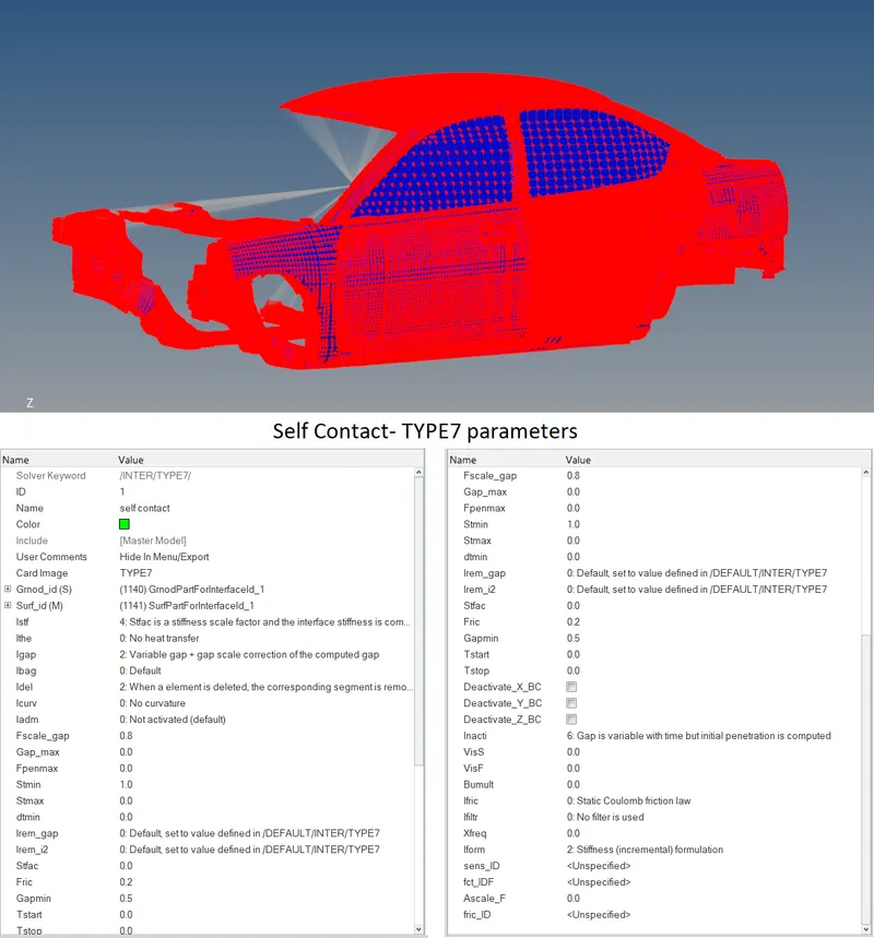
The contact interface TYPE7 is used to created self contact for the vehicle. The self contact parameters are as follows:
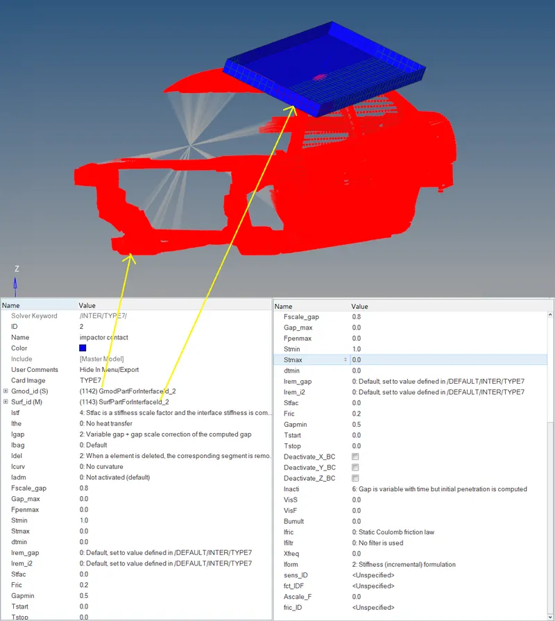
Contact between the impactor and the vehicle is given by the TYPE7 contact interface. The impactor is the master surface and the vehicle nodes are the slave nodes.
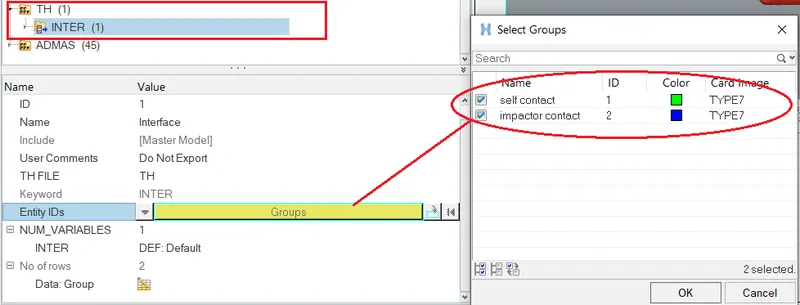
To save the data from the interface to the time history file, the contact groups are added in the TH file in the Solver browser. Refer to the image below:
The boundary condition at Suspension Shock Tower.
The reduced model has 3 suspension shock towers. The towers are first deployed with rigid connection by creating new rigid components
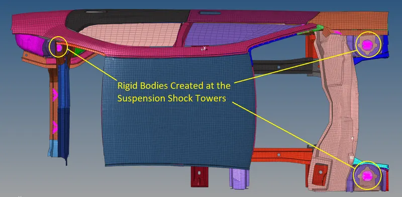
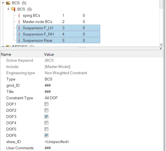
Boundary conditions are applied at the master nodes of these rigid bodies. BC is applied to keep the suspension shock tower nodes locked in Z.
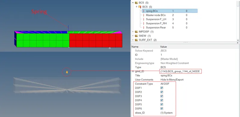
The Boundary Conditions on the Impactor:
The impactor assembly contains a spring attached for stability. A BCS is applied to fix the free end of the spring.
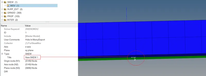
The rigid body of the impactor is given BCS such that the translation of the impactor is in the direction normal to the impactor’s face. This BCS is created by defining moving SKEW with the same direction on the face of the impactor.
Moving SKEW is as follows:
BCS is as follows:
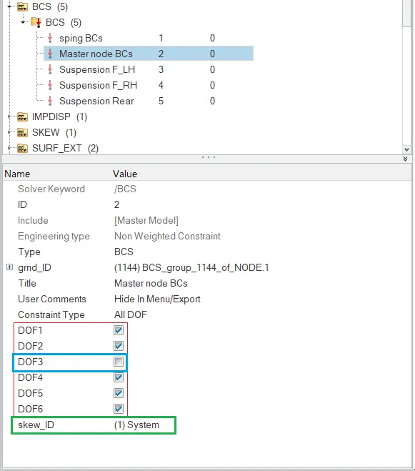
Translation motion is allowed and rest all DoF is constrained (blue box in the above image). The moving SKEW is associated with the BCS (green box).
Imposed Displacement
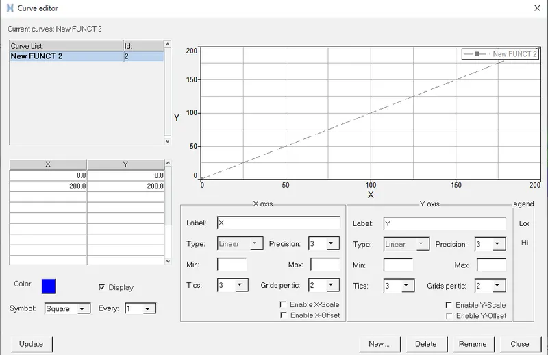
The displacement to be imposed on the impactor is such that at t=0ms with the velocity 0m/s and the displacement is 200mm at t=200ms. This can be defined as the function of the imposed displacement with XY coordinates at (0,0) and (200,200).
The function is created as follows:
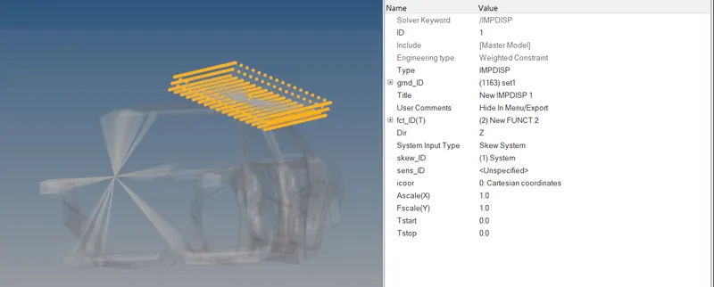
The imposed displacement is defined to the impactor nodes and is defined with function and the Skew defined above. The direction is given as Z with respect to the skew.
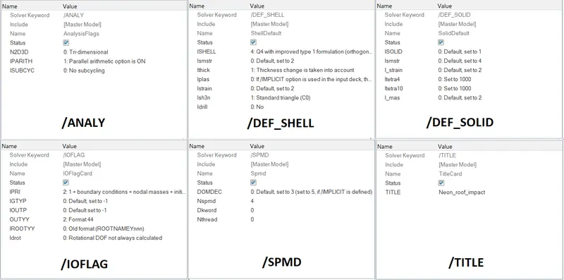
Defining Control Cards
Defining Engine_Keywords File
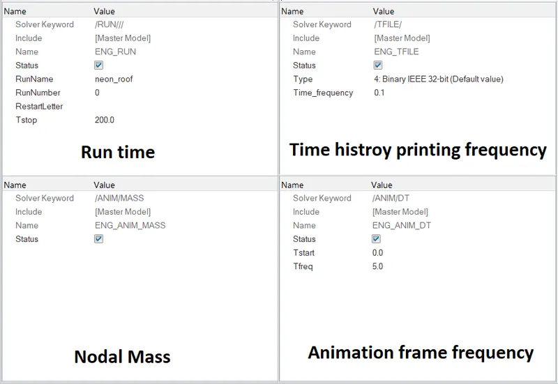
The run time is set to 200ms. The time history printing frequency is set to 0.1ms. The nodal mass animation is switched on. The animation frame frequency is set to 5ms.
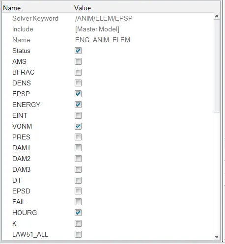
The elemental animation is switched on for elemental energy, plastic strain, hourglass energy, von Mises stress.
After setting up the output requests in the engine file, the model is checked using Model Checker. and the results are as follows:
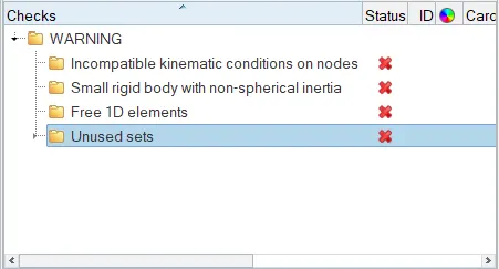
Only warnings are reported and no errors, therefore the model is ready for simulation.
The model is simulated using RADIOSS solver and the simulation results are as follows:
Simulation Results:
Animation
Energy Curves
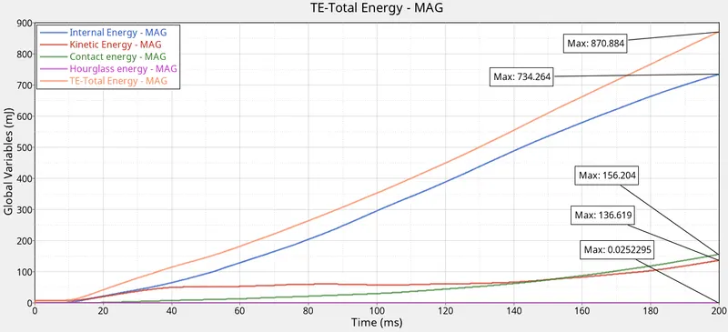
The internal energy is 734.264GPa by the end of the simulation and this is due to the deformation of the elements. The kinetic energy is very low compared to the internal energy because the car is static and the kinetic is developed is by the movement of the nodes due to the impactor motion. The impactor has a very low velocity i.e., about 1m/s. There contact energy is low as the interface used here is the TYPE7 contact interface. Hourglass energy is almost zero because the QEPH shell formulation is used. The total energy is the addition of all the energies and that's why the curve has the maximum slope.
Force vs Displacement
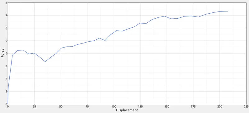
The maximum force observed is 7.3kN and the maximum displacement is about 215mm for a particular node at the junction of A-pillar and B-pillar, it's the location where the impactor has contact with the vehicle.
The mass of the vehicle is as follows:
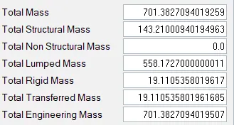
The total mass of the vehicle is 701.38kg. The target load of this vehicle can be given as follows:
Load= 3*9.8*mass of the vehicle
= 3*701.38*9.8
= 20620.572N = 20.6kN
As per FMVSS 216, the crash is said to be to fail if the load exerted by the impactor is less than the target load. In this case, the impactor load is 7.3kN and the target load is 20.6kN.
Therefore the roof crash in this case is safe enough and will not impact the passenger.
Conclusion:
- The simulation is done for a reduced model of the vehicle the results obtained may not be accurate enough as some parts are missing, but is good enough to understand the roof crash analysis.
- The simulation with the given FMVSS216 standard impactor is safe enough for the vehicle. The roof does not crush and passenger safety is achieved. The force exerted by the impactor is well within the target load.