Crash Box Simulation using LS DYNA
AIM: To simulate a crash test for a crash box using LS Dyna.
OBJECTIVE:
- Apply boundary condition to crash tube
- Create simulation for the crash tube of 1.2mm & 1.5 mm thickness and compare results
PROCEDURE:
Here are the different assumptions and information required:
- The crash box should crash into a rigid wall created using the *RIGIDWALL_ keyword.
- The material for the crash box is steel. The simulation needs to be started using elastic material to verify its correctness and later a nonlinear material card data will be provided. The thickness of the crash box is 1.2mm.
- The initial velocity for the crash box is 50 kmph
- The unit system used is gm-mm-ms.
- The simulation should satisfy either of the two situations - (1) It crashes on the rigid wall and rebounds completely or (2) it buckles and folds in the axial direction so as to come in self-contact.
- Once the simulation is completed and results, as asked for below, is collected, run another simulation by increasing the thickness of the crash box from 1.2 to 1.5mm
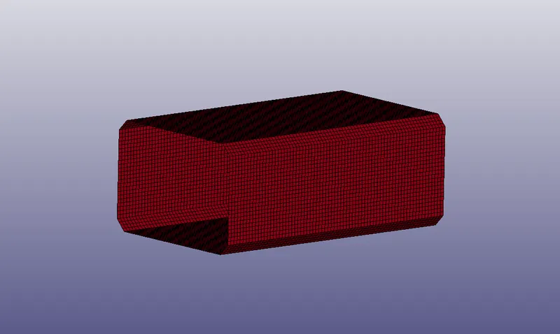
- Creating section properties
- Creating material properties
- Creating Rigid wall
- Establishing contact interface
- Applying initial velocity
- Applying control setting
- Creating Output cards in DATABASE
- Model check
The model is 1st setup with a shell thickness of 1.2mm.
Creating section properties
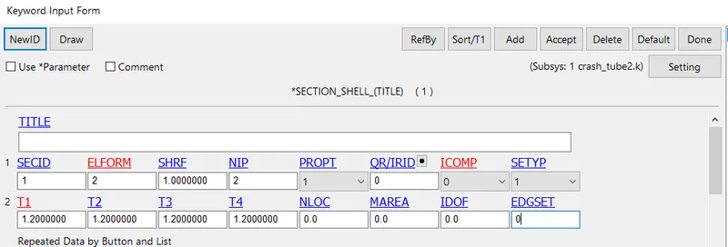
The model has only shell elements, so the section id for the shell is created. The thickness of the shell elements is 1.2mm. In Keyword Manager the section card for the shell is created and the card looks as follows:
Creating material properties
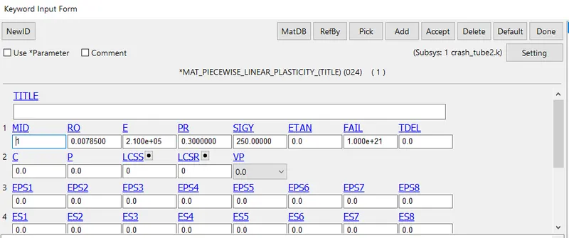
The MAT card is used to define the material properties of the crash tube. The material considered here is piecewise linear plasticity (024). The MAT card is as follows:
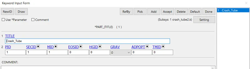
The above-created cards are linked/ assigned to the PART card. The MID and SECID are assigned for the part card as follows:
Creating Rigid wall:
The rigid wall is created using the Create Entity tool. The Rigidwall option is selected and the Cre (create new) is chosen. The rigid wall required here is a planar structure so the Planar button clicked and a node is selected on the crash tube where the Rigid wall has to be created. The same is shown below:
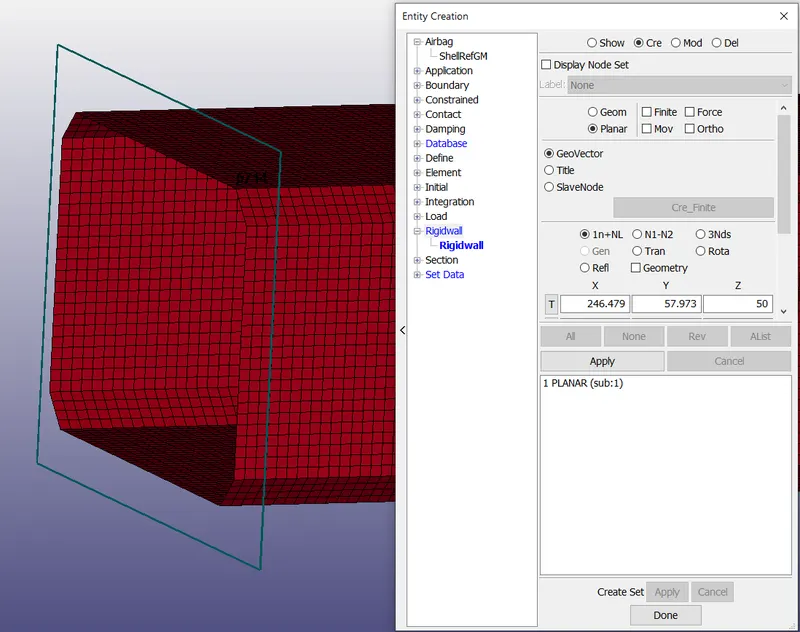
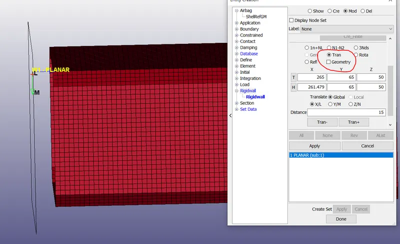
But the Rigidwall has to be placed at some distance from the crash tube so during the simulation the tube with some velocity crashes into the rigid wall. Using the Tran button the Rigidwall is moved away from the crash tube (refer to the image below).
Establishing contact interface
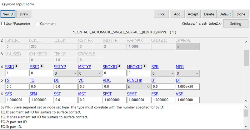
The crash tube crashes and the elements come in contact with each other, so self contact interaction occurs due to this. This kind of contact can be established using the CONTACT_AUTOMATIC_SINGLE_SURFACE card in the Contact keyword. FOr this type of contact only slave set defining is enough, using part ID the slave segment set type (SSTYP=3) is used. The self contact card is as follows:
Applying initial velocity
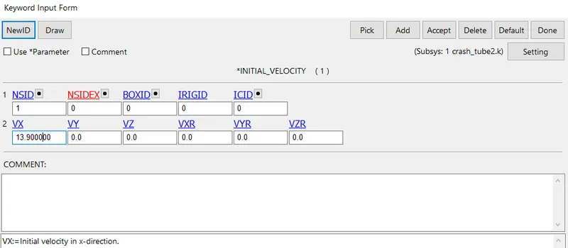
The initial velocity of the crash tube is 50kmph (13.9mm/ms). The initial velocity is given to the crash tube using the keyword Initial Velocity. The crash tube is moving in positive x-direction so the value 13.9 is entered in the VX box. The initial velocity card is as follows:
Applying control setting
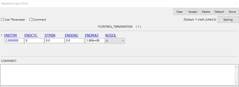
The simulation run time is set to 2ms and this is defined using the CONTROL_TERMINATION card. The card is as follows:
Creating Output cards in DATABASE
DATABASE_ASCII_options:
Specified ASCII cards are used to get outputs like GLSTAT for recording Kinetic & total energy, MATSUM for recording material Energy, RCforce- to record contact forces, SLEOUT- To record sliding energy due to contact if exist.
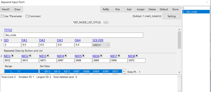
For sectional force, SECFORC is used, a set of nodes and shell elements are required. So SETIDs for the nodes and shells are created.
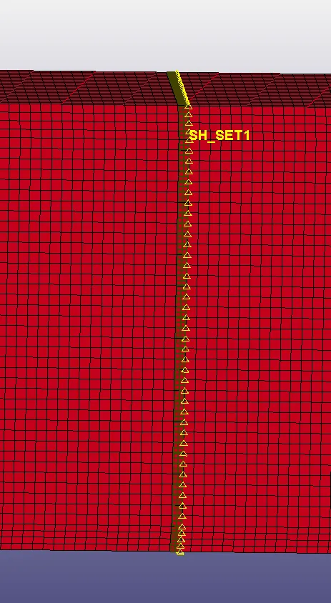
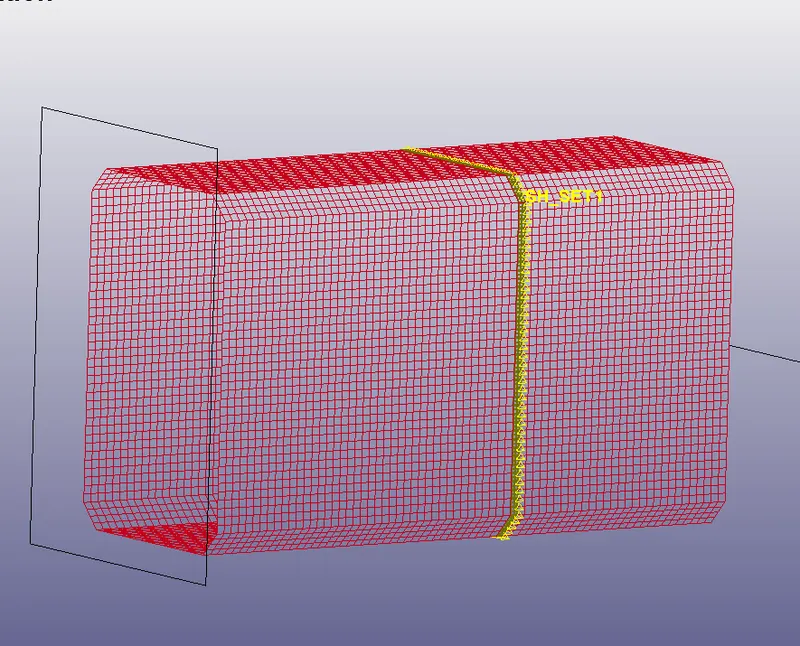
The yellow triangles represent the nodes and the dark shaded squares represent shell elements selected.
The node-set card is as follows:
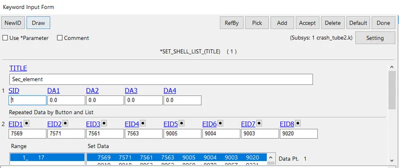
The shell set card is as follows:
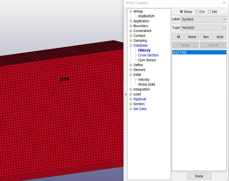
For acceleration at a particular node can also be obtained using the ASCII options NODOUT. The node at which the acceleration is to be found out can be done as follows:
Using Create Entity, under Database History type <*NODES> a node is selected. Refer to the image below:
All the ASCII_options data is created at DT=0.1
Animation:
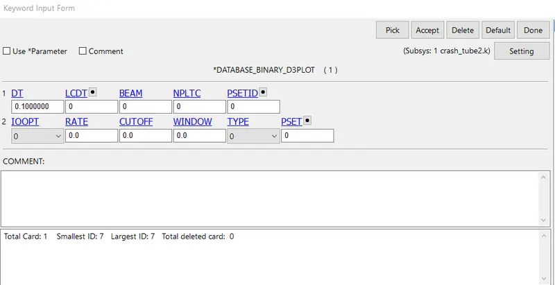
For animation keyword DATABASE_BINARY_D3PLOT is used and the card is as follows:
After all the setup is done the model is checked using Model Check and the model check is as follows:
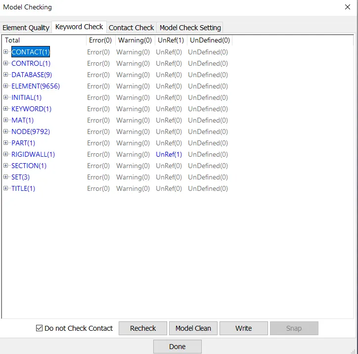
The model has no errors and warnings and is ready for simulation. The model is saved in a .k file format.
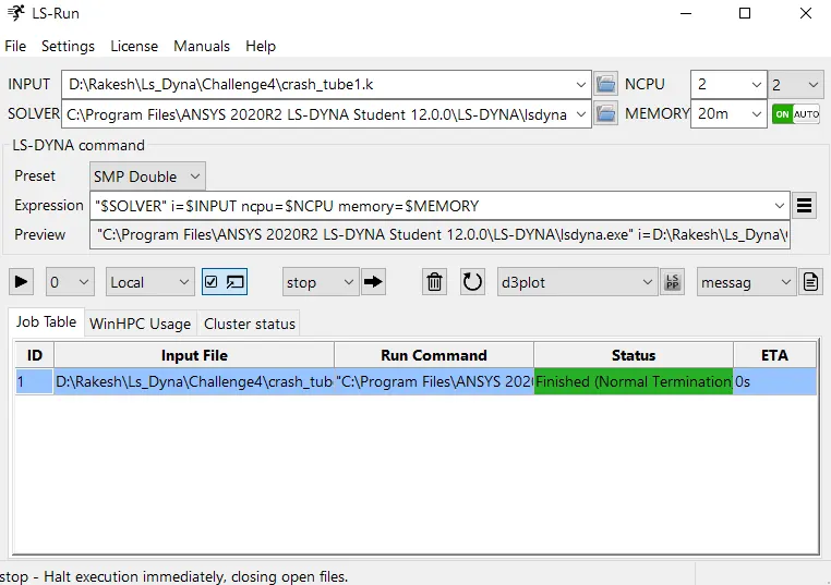
The same is loaded in LS RUN and the simulation is run as follows:
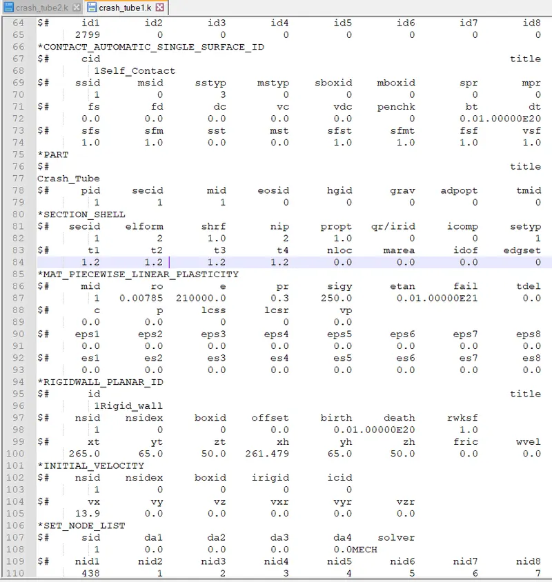
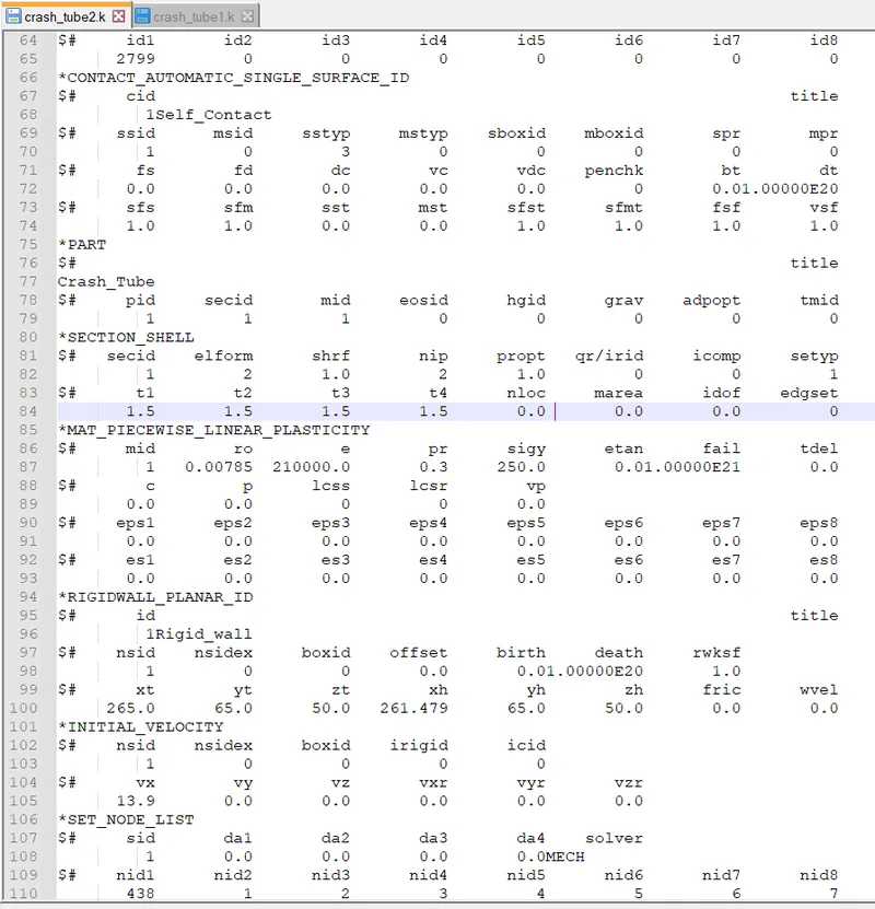
The modelling for 1.5mm shell thickness is as same that of the above case only shell thickness has to be changed. Creating a copy of the 1.2mm model .k file and pasting it in a new folder and using notepad++ the thickness is changed and the .k file is run for simulation. The images below show the changes made in the highlighted line.
RESULTS
- Animation (d3plot)
Crash Tube with 1.2mm thickness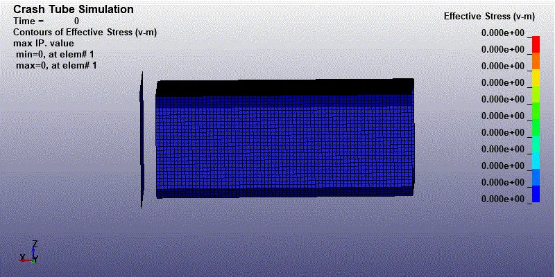
Crash Tube with 1.5mm thickness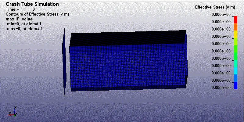
It can be seen from the above animations that the change in thickness of the shell has nothing to do with how the crash tube crashes. The crash tube crashes after 1ms of simulation in both cases. The max von misses stress values are similar in both cases which are valued at 372MPa and 374MPa at the point of contact with rigid wall in 1.2mm thickness and 1.5mm thickness respectively. - Energies Plot
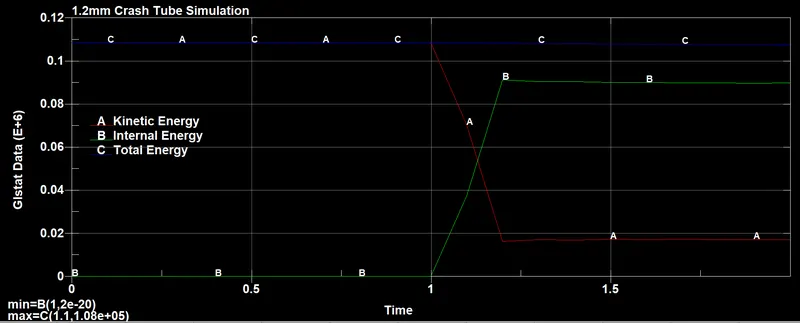
Maximum kinetic energy observed at the start of the simulation and is 1.08E+05N/mm at 1ms & Internal Energy is 1.07E+05N/mm at 1.2ms. and total energy remains constant throughout the simulation.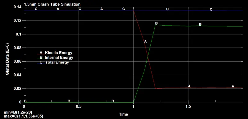
Maximum kinetic energy observed at the start of the simulation and is 1.36E+05N/mm till 1ms & Internal Energy is 1.07E+05N/mm at 1.2ms. and total energy remains constant throughout the simulation.
Sliding Interface Energy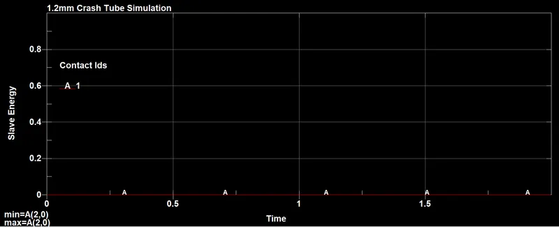
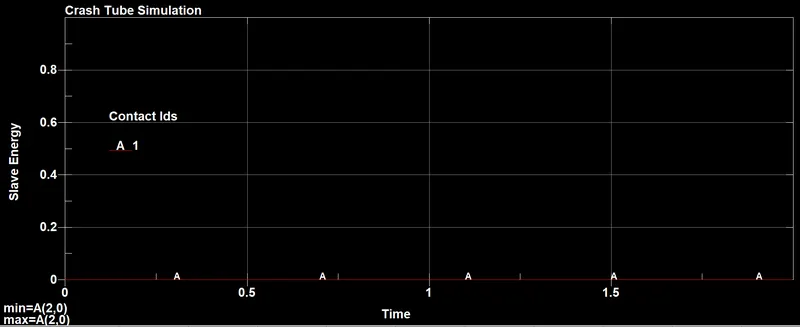
Sliding energy is observed which is zero throughout the simulation in both cases. The crush tube is hitting the rigid wall perpendicularly, usually, the sliding force is negligible in such cases. There is no friction introduced in the card which governs the sliding force between two parts. Therefore the sliding force is zero. - Acceleration of node 2799
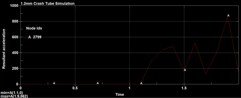
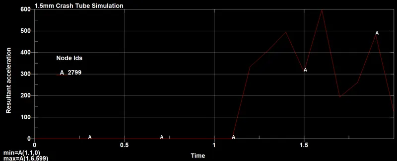
The acceleration in 1.2mm thickness has a peak value of 862m/s2 while in 1.5mm the peak is 599m/s2. The increase in thickness has reduced the acceleration value as the model 1.5mm will have more mass resulting in more force required to move it. - Sectional force
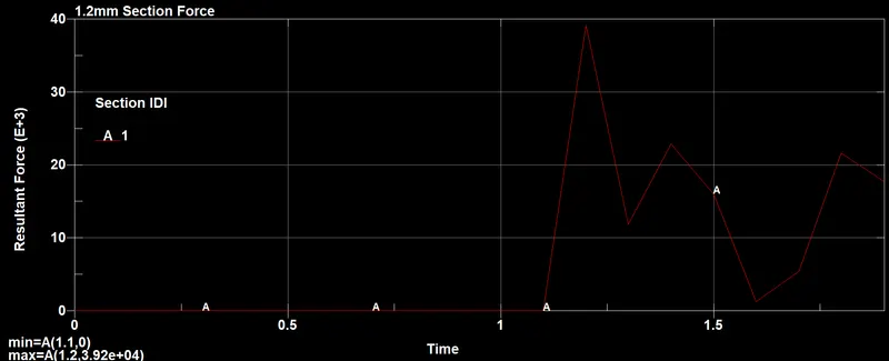
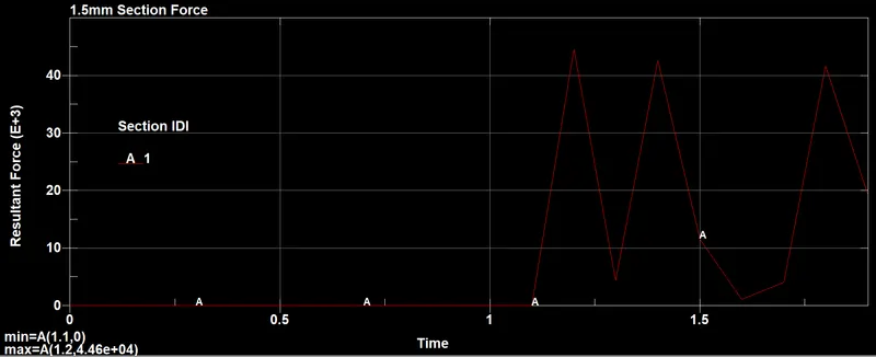
The sectional force is observed at the same section in both cases. It is seen that the curve varies in both cases. In 1.2mm thickness, the forces are less compared to 1.5mm thickness, the max value is 3.92e04 N and 4.46e04 N respectively.
- Maximum directional stress
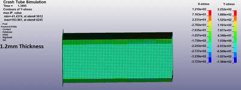
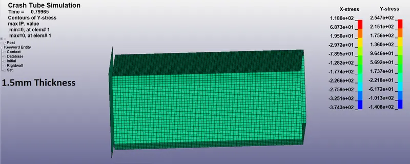
The max directional stresses for 1.2mm are 121MPa & 225.2Mpa. The max directional stresses for 1.5mm are 118MPa & 254.7MPa. The stress in x-direction has increased in 1.2mm compared to 1.5mm while the stress in y-direction has decreased in 1.2mm compared to 1.5mm. - Maximum directional strain
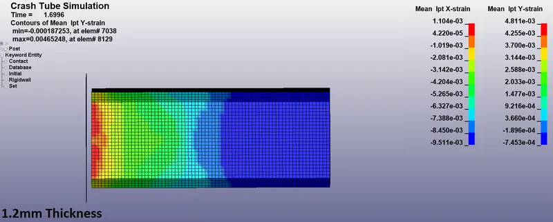
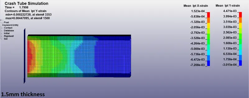
The max directional strains for 1.2mm are 1.1e-3 & 4.81e-3. The max directional strains for 1.5mm are 1.52e-4 & 4.47e-3. The stress in x-direction has increased in 1.2mm compared to 1.5mm while the stress in y-direction has increased in 1.2mm compared to 1.5mm.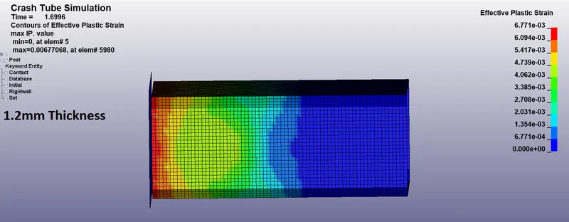
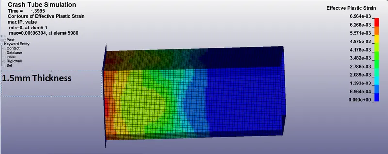
The max effective plastic strain value for 1.2mm is 6.771e-3mm and for 1.5mm it is 6.964e-3mm. The strain values are different but the change in value is not that significant and this is due to very change in stresses in both cases.
- Maximum directional stress
Conclusion
Thus, from the results, it can be concluded that the thickness of the component plays important role in understanding stress/strain/forces involved in the crash of the component. Due to the change in thickness of the crash tube following things were observed:
- The acceleration reduces with an increase in thickness.
- Sectional force is more at a particular section if the thickness is more.
- Stresses and strains change with change in thickness.