2R Robotic Arm Simulation using Matlab
FORWARD KINEMATICS:
Forward kinematics is the process of getting the position and velocity of the end effector, from the given joint angles and positions. In this project, we are going to simulate the positions of the two arms of the 2R Robotic arm by pre-defining the positions of the three joints of the arm.
2R ROBOTIC ARM:
A 2R Robotic arm has two links and two joints, each having one degree of freedom. So, the DOF of this 2R Robot is 2 DOF. Here the R stands for Revolute joint. An example of this robotic arm is shown in the figure below. Another good example is our arm when it is restricted to only one plane.
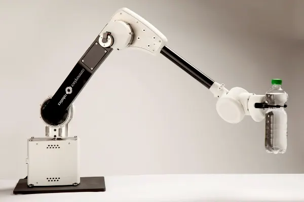 Image displaying a real-life 2R Robotic Arm.
MATLAB
MATLAB (Matrix Laboratory) is a multi-paradigm programming language developed by MathWorks. It allows matrix manipulations, plotting of functions and data, implementation of algorithms, creation of user interfaces, and is capable of interfacing with programs written in other languages.
I. AIM OF THE PROJECT:
To write a program in Matlab to simulate the forward kinematics of a 2R Robotic Arm.
II. MATLAB CODE:
% Inputs

l1 = 1; % Length of link 1
l2 = 0.5; % Length of link 2

O1 = linspace(0,90,10); % Angle of link 1 wrt the x axis
O2 = linspace(0,90,10); % Angle of link 2 wrt the x axis

% Origin co-ordinates

x0 = 0;
y0 = 0;

ct = 1; % Counter for displaying plots

% Initializing the angles

Theta1 = 0;
Theta2 = 0;

% The loop

for i = 1:length(O1)
    Theta1 = O1(i); % Angle made by link 1 wrt the base

    % x1 and y1 are the co-ordinates of the elbow joint

    x1 = l1*cosd(Theta1);
    y1 = l1*sind(Theta1);

    for j = 1:length(O2)
        Theta2 = O2(j); % Angle made by link 2 wrt the base

        % x2 and y2 are the coordinates of the end joint

        x2 = x1 + l2*cosd(Theta2);
        y2 = y1 + l2*sind(Theta2);

        % Plotting

        plot([x0 x1],[y0 y1],[x1 x2],[y1 y2]) % The plot variables
        axis([-0.1 1.6 -0.1 1.6]) % Setting the axis of the plot
        pause(0.0001) % Time b/w plots
        M(ct) = getframe(gcf); % Write frames for making the video
        ct = ct + 1; % Incrementing the counter
    end
end

% The movie

movie(M);
videofile = VideoWriter('forward_kinematics_example.avi','Uncompressed AVI'); % Naming and formating the video
open(videofile) % Open the video editor
writeVideo(videofile,M) % Convert the image to frame
close(videofile) % Close the video writerIII.1. CODE RESULT:
For every change in the angle of link-1, link-2 moves from 0 degrees to 90 degrees with respect to the x-axis. The link-1 also moves from 0 degrees to 90 degrees during the simulation.
III.2. STEPWISE CODE EXPLANATION:
- Pre-define the length of the link-1 (l1) and link-2 (l2) in meters.
- Create two arrays of angles (o1 and o2) from 0 to 90 degrees with 10 angles each using the linspace command.
- Pre-define the origin coordinates (x0, y0) = (0,0).
- Initiate the counter (ct = 1).
- Initialize the angles as theta 1= 0 and theta 2 = 0. These are the angles between link-1 and base; and link-2 and base, respectively.
- Initialize the for loop:
- Initiate i from 1 to the length of o1 matrix which is 10. So the values of i will change from 1 to 10 for every loop iteration.
- Calculate the co-ordinates of joint 2 (x1, y1) using the kinematic formulae: x1 = l1*cosd(Theta1) and y1 = l1*sind(Theta1) for every value of Theta1.
- Initiate j from 1 to the length of o2 matrix which is 10. So the values of j will change from 1 to 10 for every loop iteration.
- Calculate the co-ordinates of joint 3 (x2, y2) using the kinematic formulae: x2 = l2*cosd(Theta2) and y2 = l2*sind(Theta2) for every value of Theta2.
- Plot the graph by inputting all the coordinates, (x0, x1), (y0,y1),(x1,x2),(y1,y2). In this manner so that all the plots appear in the same window rather than creating multiple plot windows.
- Set the axis of the plot
- Set time between the plots. Lower the time, shorter will be the video.
- Feed the frames obtained into an array M(ct) using the following command: M(ct) = getframe(gcf); New images will be added to the consecutive positions in the array as the value of ct is incremented for every loop iteration.
- End the loops.
- Initialize writing the movie from the set of frames collected by the M(ct) array.
- The movie(M) command will initiate the writing process from M.
- Describe and set the format of the video file to be created using the VideoWriter() function
- Open the video editor using open() function
- Write the video using the writeVideo() function
- Close the editor using the close() function. This will also save the video.
III.3. ERRORS FACED AND THEIR SOLUTIONS:
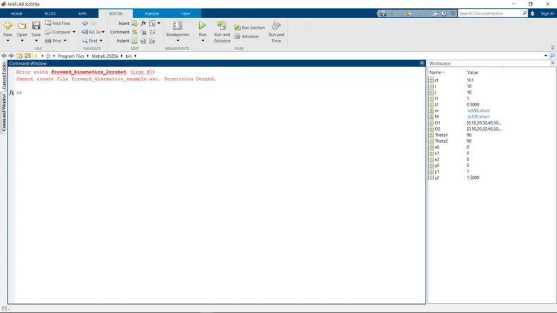
Error: "Cannot create file forward_kinematics_sample.avi. Permission Denied."
Solution: Restart and Run MATLAB with full administrator access. Also, add the program file location to Matlab root.
Error Screenshot: