GENEVA MECHANISM MOTION STUDY USING SOLIDWORKS
The Geneva drive or Maltese cross is a gear mechanism that translates a continuous rotation movement into intermittent rotary motion. The drive wheel is usually equipped with a pin that reaches into a slot located in the driven wheel that advances it by one step at a time.
There are two types:
- External Geneva Mechanism: The slots are grooved around the driven gear.
- Internal Geneva Mechanism: The slots are grooved inside the driven gear.
Here are some animations,
External Geneva drive:
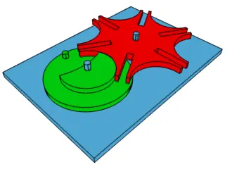
source: https://en.wikipedia.org/wiki/Geneva_drive#/media/File:Geneva_mechanism_6spoke_animation.gif
Internal Geneva drive:
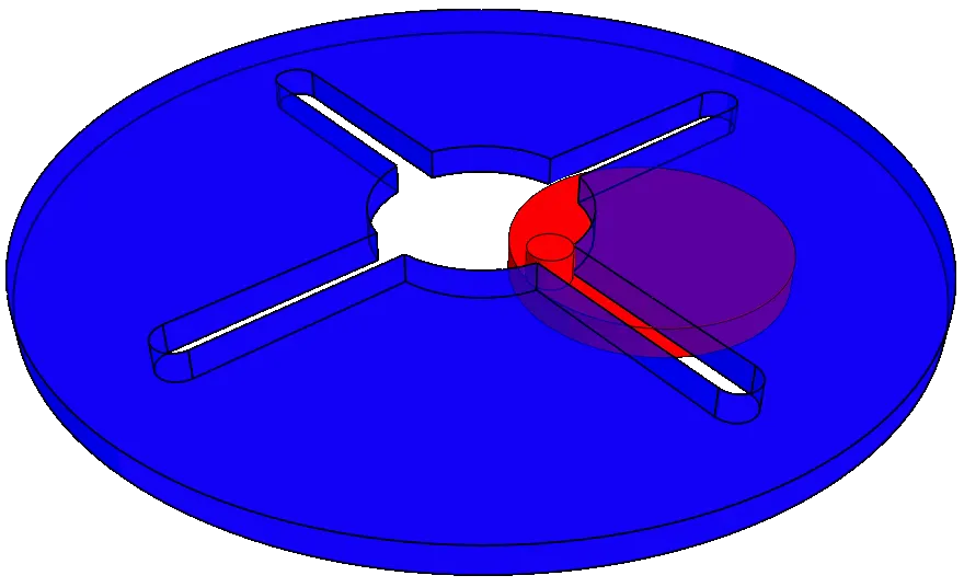
source: https://upload.wikimedia.org/wikipedia/commons/7/7a/Internal_Geneva_wheel_ani.gif
This project aims at performing motion analysis of the Internal Geneva mechanism by producing results such as contact force, angular acceleration and velocities of the driver and driven gears.
Aim:
To perform a motion analysis of the Internal Geneva drives using SOLIDWORKS motion.
Objectives:
- Create 3D models for driver and driven wheels.
- Perform motion analysis by rotating the driver wheel at 10 RPM @ 60 fps.
- Obtain the following plots
- Contact force (between driving and the driven wheel) as a function of time.
- Angular Displacement of the driven wheel.
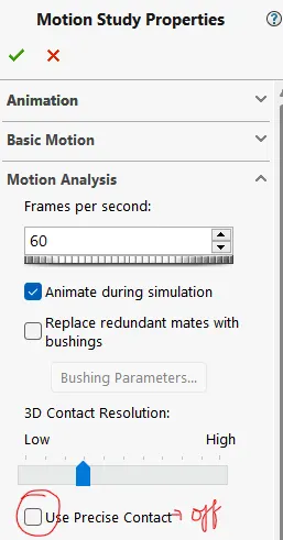
- Compare the contact forces with and without "Precise contact"
- Show image for precise contact selection
- Export the results that you get to Excel and make the plots over there.
Given data:
2D CAD drawings to create the 3D model of the internal Geneva mechanism
1. Driven gear
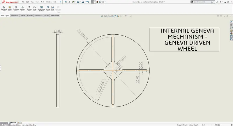
2. Driver gear
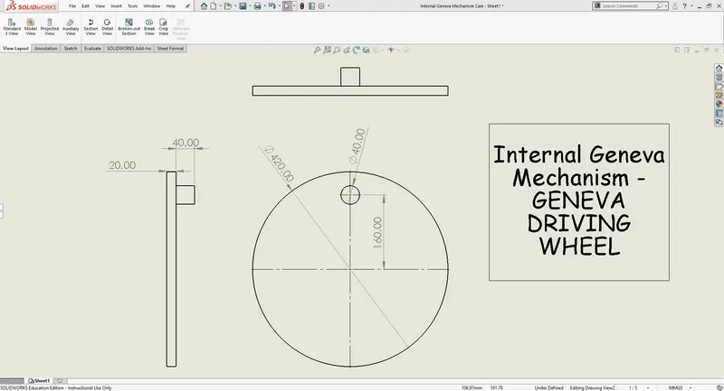
3D CAD Models:
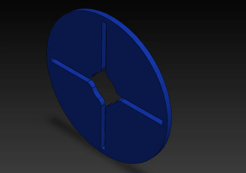
1. The Driven gear
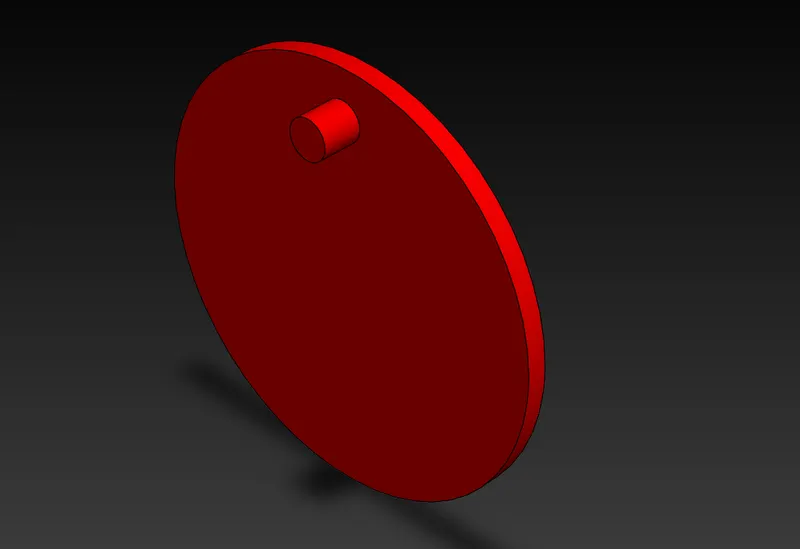
2. The Driver gear
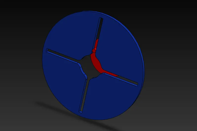
3. Complete Assembly
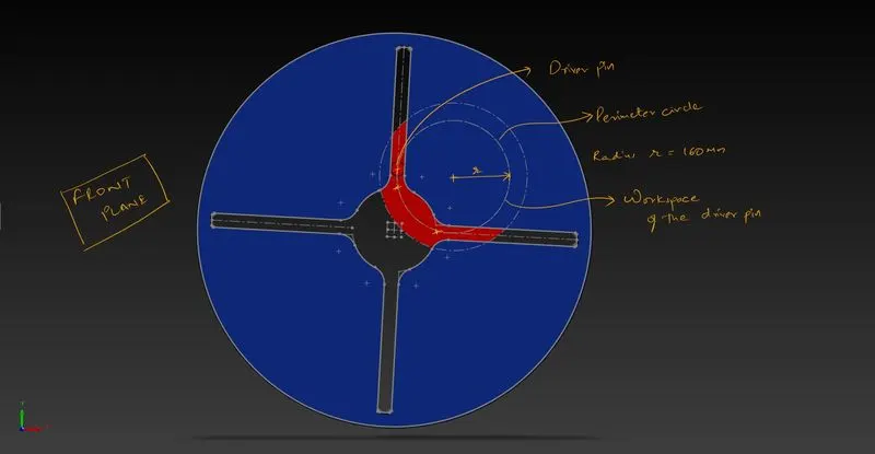
4. How to position the driven and driver gear in the assembly:
RESULTS:
1. 10 RPM 60 FPS
| Precise contact: ON | Precise contact: OFF |
|
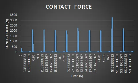
The contact force between the driver and driven gear
The precision contact mode precisely pinpoints the place in the mechanism where the jerk is experienced and also gives a very accurate measurement of the contact force at each contact of the driver and the driven gears. |
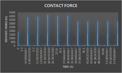
The contact force between the driver and driven gear
Without the precision contact mode turned on, the contact forces at each contact of the driver and driven gears are significantly higher. This has a smooth curve and hence does not read the jerk in the mechanism. |
|
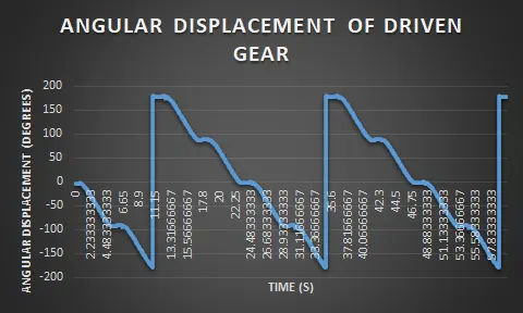
The angular displacement of the driven gear
Same angular displacement trend. |
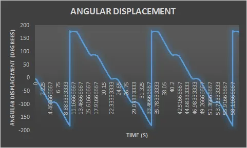
The angular displacement of the driven gear
Same angular displacement trend. |
|
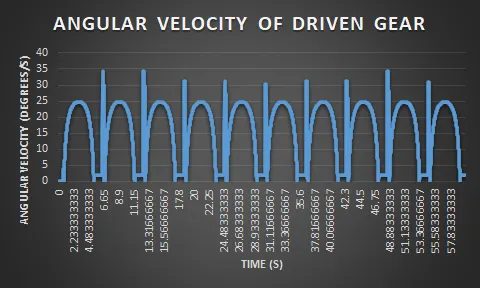
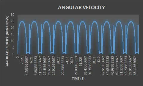
Angular velocity of the driven gear
|
Angular velocity of the driven gear
|
|
The angular velocity of the driver remains constant as it is connected to a contact speed rotary motor. |
The angular velocity of the driver remains constant as it is connected to a contact speed rotary motor. |
Precise contact selection:
2. 20 RPM 120FPS Precise contact: ON
The contact force between the driver and driven gear
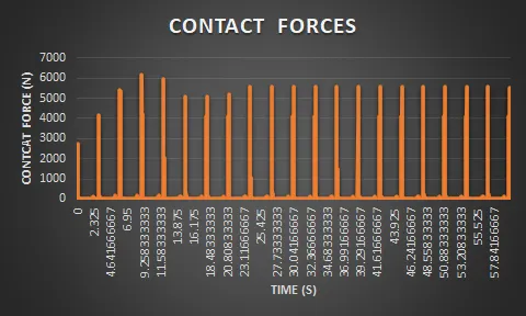
Comparing this to the 10 RPM case, we can clearly see that the trend of the contact forces between the drive and the driven gear is now smoother and minimal jerks were experienced than the latter. By this observation, we can say that increasing the angular velocity does in fact result in a decrease in jerks.
The angular displacement of the driven gear
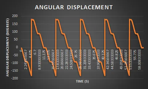
The angular displacement is consistent with time for every -180 to 180 degrees. Derived from the fact that the angular velocity of the driver is constant throughout.
Angular velocity of the driven gear
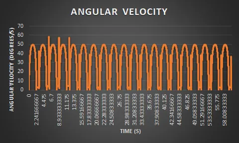
The angular velocity plot is completely relatable to the contact forces plot. As you can see the jerks were experienced from 6.7s to 11.75s.
Angular velocity of the driver gear
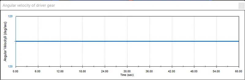
This plot shows that the driver stays at a constant speed throughout the simulation.
OBSERVATIONS:
1. Jerks were experienced when the pin of the driver wheel comes in first contact with the driven wheel.
2. Increasing the driver wheel speed decreases the jerkiness of the mechanism but it won't eliminate it.
3. The fit between the driven slot and the driver pin is a tight fit with 0 mm clearance. This is not desirable and is the main reason for the jerks experienced by the mechanism. Providing a clearance fit with an optimal clearance will completely eliminate the jerkiness of the mechanism, hands down.
4. Providing a clearance fit will also bring down the contact forces significantly and bring down the wear and tear of the parts in the mechanism.
ANIMATION:
Internal Geneva mechanism animation
CONCLUSION:
The multi-body motion simulation of the internal Geneva mechanism is hence complete. The ultimate solution to the jerkiness problem is to introduce a clearance fit between the driver pin and internal driven slots.
REFERENCES:
1. Wikipedia: https://en.wikipedia.org/wiki/Geneva_drive