MBD of Shaper machine using SOLIDWORKS Motion
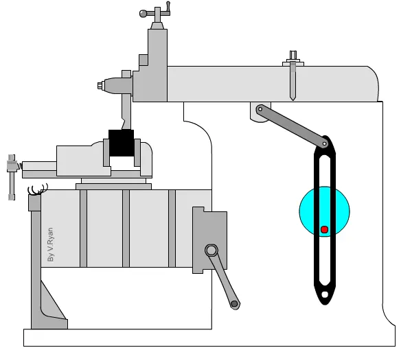
Shaper Machines work under the principle of 'Quick return mechanism'. It is a reciprocating type of machine, which uses a single-point cutting tool. The tool will be fixed in the ram. The machine vice/table holds the workpiece and the cutting tool reciprocates over it, by the repeated reciprocating motion of the cutting tool machining is done.
During forward stroke, machining takes place and there is no machining that takes place during the return stroke. Hence it is designed in such a way that the time taken during the return stroke will be lesser than the time taken to forward stroke. It helps machine the keyways, gears, splines, contours and smooth rough surfaces.
MECHANISM
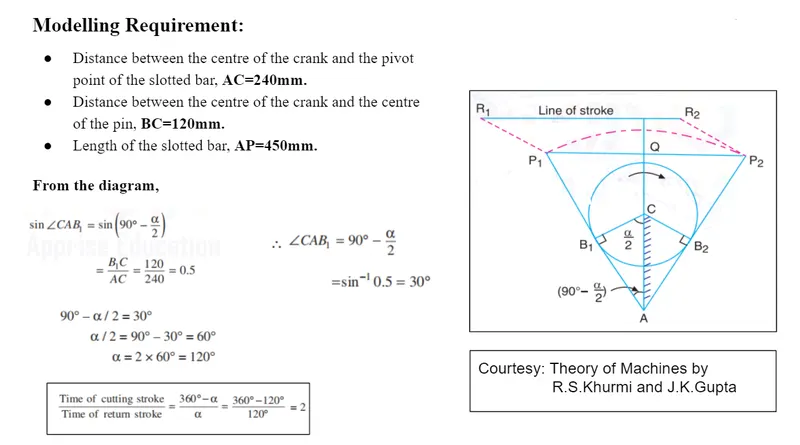
In the Quick return mechanism, the rotary motion is converted into reciprocating motion. There is a higher pair between the crank and slotted bar. as the crank rotates, the slotted bar oscillates. The oscillatory motion of the slotted bar is transformed into the reciprocating motion of the ram using the connecting rod. The shaper machine is designed in such a way that the time taken for the cutting stroke is twice that of the return stroke.
PROCEDURE FOLLOWED
PARTS OF A SHAPER MACHINE
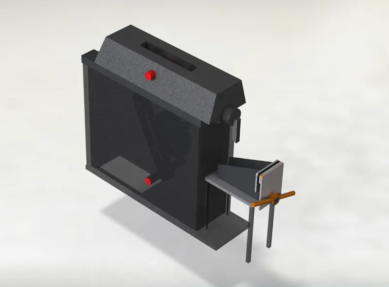
1. THE BODY
The body is a rigid component that holds all other parts, so it has to be robust and made up of Cast Iron. The provisions to the assembly crank and the shaft which supports the slotted bar are provided as shown in the figure.
2. CRANK
The crank is the rotating component, the motor input will be given to the crank. It has the pin, the centre axis of the pin and the centre axis of the crank is made offset by a certain distance. This distance is the radius of the crank.
3. SHAFT
The shaft is the component that supports the slotted bar. At the mid-position of the shaft, the slotted bar is mounted and the two ends of the shaft are supported by the body.
4. SLOTTED BAR
One end of the slotted bar is mounted to the shaft and the other end is mounted to the connecting rod. The assembly will be made in such a way that the pin moves inside the slot of the slotted bar.
5. CONNECTING ROD
This connects the slotted bar with the Ram. The oscillatory motion of the slotted bar is converted into the reciprocating motion of the Ram by using the connecting rod.
6. BODY COVER
Body cover is mounted at the top of the body, it has the provision to support the Ram. The design is made in such a way that there will be the only linear motion of the Ram over the body cover. There is a gap at the mid-portion of the body cover, between this gap the connecting rod moves.
7. RAM
Ram is fixed on top of the body cover and it holds the cutting tool. The connecting connected at the mid-portion of the Ram.
ASSEMBLY PROCEDURE
1. MATES TO FIT THE BODY COVER
- The body and the body cover are imported to the assembly, the first part(body) imported to the assembly will be in a fixed condition.
- The following mates are given to fit the body and body cover.
- Coincident mate b/w the faces of the body and
Body cover. Coincident mate b/w the front edges of the body. Coincident mate b/w the faces of the body and body cover. Coincident mate b/w the side edges of the body and body cover.
2. MATES TO FIX THE RAM
The shaper is imported to the assembly, The following mates are given to fit the Ram and body cover.
Distance mate of 0.25mm is given b/w the faces of the Ram and body cover. Distance mate of 0.25mm is given b/w the side edges of the Ram and body cover.
3. MATES TO FIX THE SHAFT
The shaft is imported to the assembly, The following mates are given to fit the Shaft to the body.
Concentric mate b/w the cylindrical faces of the shaft and hole in the body. Coincident mate b/w the front plane of the shaft and top plane of the body.
4. MATES TO FIX SLOTTED BAR
The slotted bar is imported into the assembly, The following mates are given between the shaft and the slotted bar.
The concentric mate between the outer cylindrical face of the shaft and the hole of the connecting rod. The coincident mate between the front plane of the connecting rod and the top plane of the body.
5. MATES TO FIT THE CRANK
The crank is imported into the assembly, The following mates are given between the crank and the slotted bar.
The concentric mate between the hole in the body and the crankshaft. Tangent mate b/w the circular edge of the crankshaft and hole in the body. Slot mate b/w the pin of the crank and the slot of the slotted bar.
6. MATES TO FIX THE SHAFT
The shaft is imported into the assembly. The following mates are given between the shaft and the Ram.
The concentric mate between the hole in the Ram and shaft. The coincident mate between the front plane of the shaft and the top plane of the assembly.
7. MATES TO FIT THE CONNECTING ROD
The connecting rod is imported into the assembly. The following mates are given between the connecting rod, shaft and the slotted bar.
Slot mate between the slot in the connecting rod and shaft. Concentric mate b/w the circular face of the connecting rod and slotted bar. The coincident mate between the front plane of the connecting rod and the front plane of the slotted bar.
8. MATES TO FIX MACHINE VICE
The Machine Vice assembly which was covered in the course video is imported into the assembly.
The following mates are given between the Machine Vice and body.
The coincident mate between the front face of the body and the back face of the machine vice. Distance mate of 400mm b/w the bottom face of the body and bottom face of the machine vice. The coincident mate between the right plane of the machine vice and the top plane of the assembly.
COMPLETE ASSEMBLY AND RENDER
MOTION ANALYSIS
- A new motion study is created.
- The time frame for the simulation is fixed as 5 s.
- Motor input is given to the crank by specifying the 30 rpm.
- Materials for the various parts are specified using contacts as steel.
- Now, the simulation is started by giving calculate option.
- Animation and output plots are obtained after the simulation completes.
- The same process is repeated for 60 and 90 RPM.
OUTPUT PLOTS AND RESULTS:
TRACE DIAGRAM
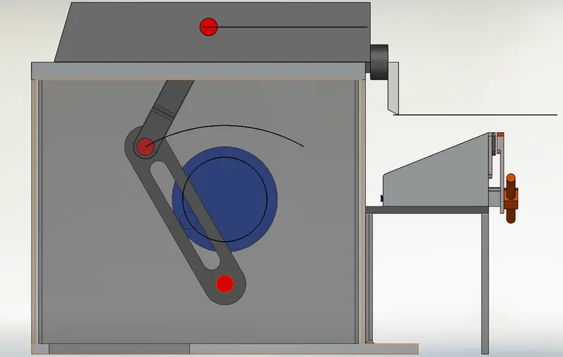
The black lines represent the trace. Notice how similar it is to the modelling requirement diagram.
LINEAR DISPLACEMENT OF CUTTING TOOL
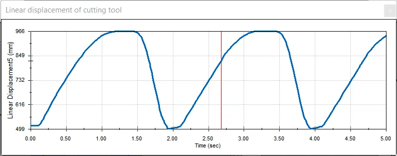
From the graph, it is observed that,
- The maximum displacement of the cutting tool = 966-499 = 467 mm
- Time taken for the cutting stroke = 1.35 s (30 RPM)
- Time taken for the return stroke = 0.65 s (30 RPM)
CONTACT FORCE BETWEEN THE CRANKPIN AND SLOTTED BAR AT DIFFERENT CRANK SPEEDS
- 30 RPM
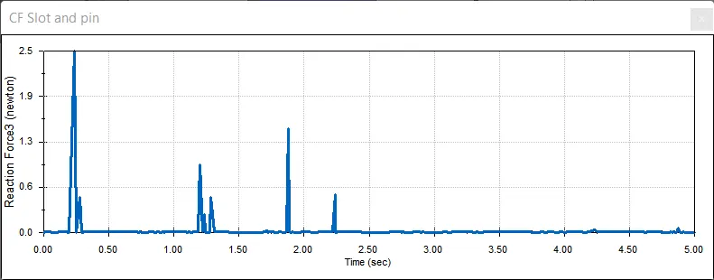
The contact force between the crankpin and the slotted bar at 30 RPM is at a maximum of 2.5 N (No load).
- 60 RPM
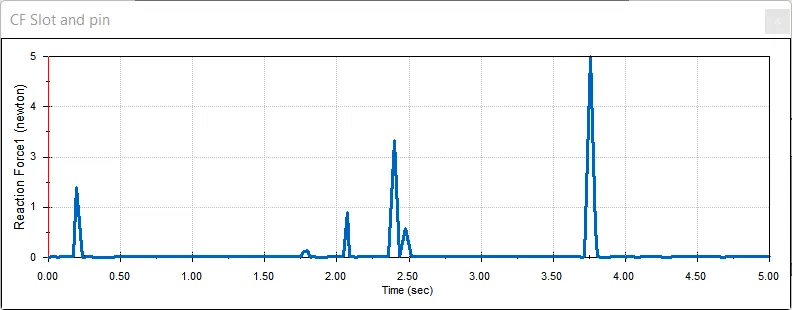
The contact force between the crankpin and the slotted bar at 60 RPM is at a maximum of 5 N (No load).
- 90 RPM
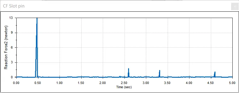
The contact force between the crankpin and the slotted bar at 90 RPM is at a maximum of 13 N (No load).
After seeing the contact forces for different speeds, we can see that the initial contact force between the crankpin and the slotted bar is higher for higher crank speeds. Once the slotted bar gains momentum, the contact forces can be neglected.
LINEAR VELOCITY OF CUTTING TOOL
Crank speed = 90 RPM
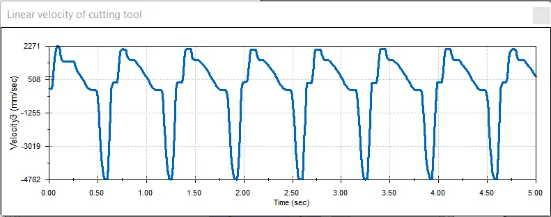
Inference from the plot:
During cutting stroke, the maximum velocity of the tool is around 2271 mm/s. But during the return stroke, the velocity of the cutting tool is around 4782 mm/s. Our mechanism is designed in such a way that the time taken to the cutting stroke is almost twice the time taken to the return stroke. Hence, the velocity during the return stroke is comparatively high.
CONCLUSION
Thus the 3D modelling of the Shaper Machine is done and the Motion analysis is carried out to get some useful plots for further analysis.
BEFORE GOING, Here is a short animation of the shaper machine in action.
THANK YOU!