MBD Simulation of IC Engine Valve Train (Cam-in-block) using SOLIDWORKS
A valvetrain or valve train is a mechanical system that controls the operation of the intake and exhaust valves in an internal engine. The intake valves control the flow of air/fuel mixture (or air alone for direct-injected engines) into the combustion chamber, while the exhaust valves control the flow of spent exhaust gasses out of the combustion chamber once combustion is completed.
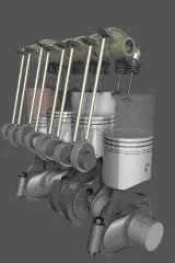
The cam-in-block valvetrain layout of piston engines is one where the camshaft is placed within the cylinder block, usually besides and slightly above the crankshaft in a straight engine or directly above the crankshaft in the V of a V engine. This contrasts with an overhead camshaft (OHC) design which places the camshafts within the cylinder head and drives the valves directly or through short rocker arms.
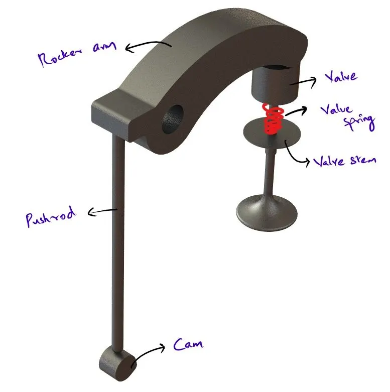
The valvetrain consists of all the components responsible for transferring the rotational movement of the camshaft into the opening and closing of the intake and exhaust valves. Typical components are listed below in order from the crankshaft to the valves.
CAMSHAFT
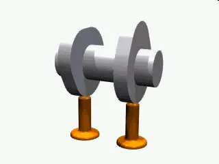
The timing and lift profile of the valve opening events are controlled by the camshaft, through the use of a carefully shaped lobe on a rotating shaft. The camshaft is driven by the crankshaft and in the case of a four-stroke engine rotates at half the speed of the crankshaft.
CAM
A cam is a rotating or sliding piece in a mechanical linkage used especially in transforming rotary motion into linear motion. It is often a part of a rotating wheel (e.g. an eccentric wheel) or shaft (e.g. a cylinder with an irregular shape) that strikes a lever at one or more points on its circular path.
PUSHROD
Pushrods are long, slender metal rods that are used in overhead valve engines to transfer motion from the camshaft (located in the engine block) to the valves (located in the cylinder head). The bottom end of a pushrod is fitted with a lifter, upon which the camshaft makes contact. The camshaft lobe moves the lifter upwards, which moves the pushrod. The top end of the lifter pushes on the rocker arm, which opens the valve.
ROCKER ARM
Depending on the design used, the valves are actuated by a rocker arm, finger or bucket tappet. Overhead camshaft engines use fingers or bucket tappets, upon which the cam lobes contact. Overhead valve engines use rocker arms, which are actuated by a pushrod and pivot on a shaft or individual ball studs to actuate the valves.
VALVE
A valve is a device that regulates, directs or controls the flow of gases or liquid by opening, closing, or partially obstructing various passageways. Valves are technically fittings but are usually discussed as a separate category. In an open valve, fluid flows in a direction from higher pressure to lower pressure.
VALVE STEM
A valve stem is a component that directs the valve direction and supports the valve spring. It restricts the motion of the valve to the requirement. The valve spring is used to retract the valve after the rocker arm pushes it downwards.
AIM
- To carry out a motion analysis of a Cam-in-block IC engine Valvetrain using SOLIDWORKS Motion
OBJECTIVES
- Run the simulation using the below parameters
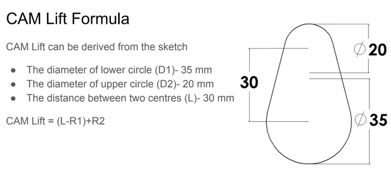
- Cam lift = 3.5 mm, Cam speed = 1500 RPM, Material = Cast carbon steel
- Cam lift = 6 mm, Cam speed = 1500 RPM, Material = Cast carbon steel
- To obtain the Valve lift
- To determine the contact forces between the following
- Cam and Push Rod
- Pushrod and Rocker Arm
- Rocker Arm and Valve
- Explain why the contact force between the Rocker arm and valve varies while measuring for the X-direction and measuring for magnitude.
RESULTS:
CAM LIFT = 3.5 mm Spring parameters - Free length 40 mm, 1 N/mm
- LINEAR DISPLACEMENT OF VALVE (VALVE LIFT)
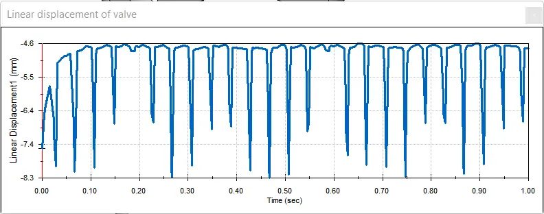
The valve head linearly displaces 3.7 mm (8.3 - 4.6) from top to bottom.
- CONTACT FORCE BETWEEN CAM AND PUSHROD
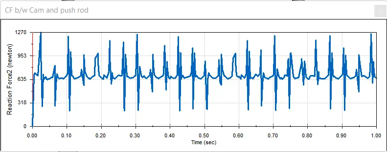
The contact force between the cam and the pushrod ranges from 180 N to 1270 N. The lower contact force is when the pushrod is in contact with the circular surface of the cam. The peak contact force is when the cam's peak pushes on the pushrod.
- CONTACT FORCE BETWEEN VALVE AND ROCKER ARM (MAGNITUDE ONLY)
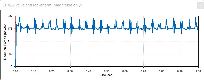
The contact force (magnitude only) between the valve and rocker arm ranges from 150 N to 237 N.
- CONTACT FORCE BETWEEN VALVE AND ROCKER ARM (ALONG X-DIRECTION)
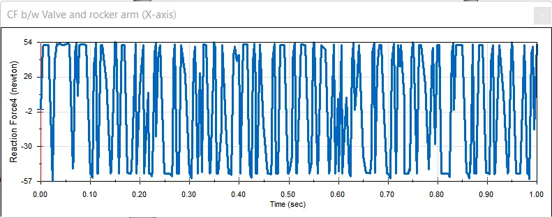
The contact force along the x-direction between the valve and rocker arm ranges from 54 N to -57 N. -ve value represents the rocker arm pushing the valve. The +ve value represents the valve pushing the rocker arm due to spring action.
Cam lift of 6 mm: Spring parameters - Free length 40 mm, 1 N/mm
- LINEAR DISPLACEMENT OF VALVE (VALVE LIFT)
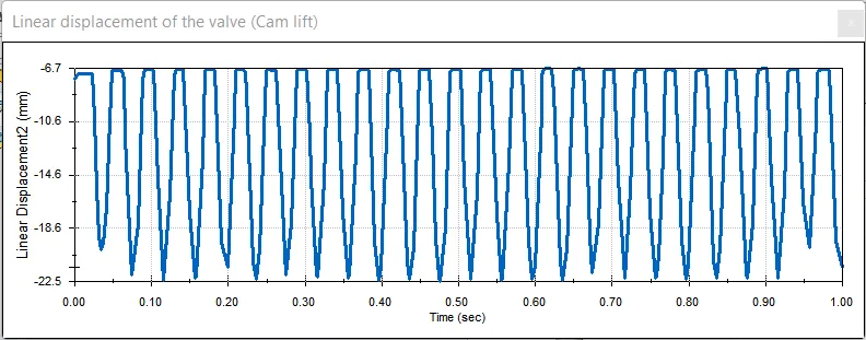
The valve head linearly displaces 15.8 mm (22.5 - 6.7) from top to bottom.
- CONTACT FORCE BETWEEN VALVE AND ROCKER ARM (MAGNITUDE ONLY)
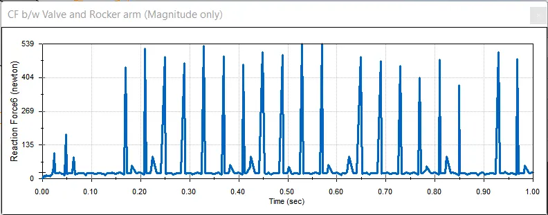
The contact force (magnitude only) between the valve and rocker arm ranges from 0 N to 539 N.
- CONTACT FORCE BETWEEN VALVE AND ROCKER ARM (ALONG X-DIRECTION)
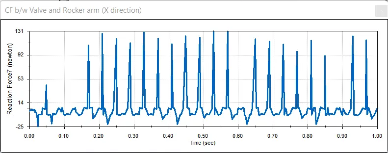
The contact force along the x-direction between the valve and rocker arm ranges from -25 N to 131 N. -ve value represents the rocker arm pushing the valve. The +ve value represents the valve pushing the rocker arm due to spring action.
- CONTACT FORCE BETWEEN CAM AND PUSHROD
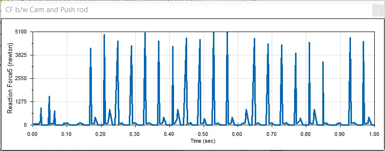
The contact force between the cam and the pushrod ranges from 0 N to 5100 N. The lower contact force is when the pushrod is in contact with the circular surface of the cam. The peak contact force is when the cam's peak pushes on the pushrod.
SIMULATION RESULTS:
Contact forces
| Parts | Cam lift 3.5 mm | Cam lift 6 mm |
| Cam and pushrod | 180 to 1270 N | 0 to 5100 N |
| pushrod and rocker arm | 0 to 1150 N | 0 to 5135 N |
| Rocker arm and valve | 150 to 237 N | 0 to 539 N |
FINALLY,
Why the contact force between the Rocker arm and valve varies while measuring for the X-direction and measuring for magnitude?
When we study the motion of the rocker arm and the valve, we can see that the rocker arm moves in an arc in the x-y plane. The valve moves linearly along the y-axis. The motion of the rocker arm has two components, x and y. The valve has only one component y. The magnitude of the rocker arm only pushes the valve downwards but the x-axis gives us only the friction force between the rocker arm and the valve. Hence, both the values are different.
REFERENCES