PLANATARY GEAR TRAIN MOTION STUDY & SIMULATION USING SOLIDWORKS
A planetary gear set (also known as an epicyclic gear train) consists of two or more gears mounted so that the centre of one gear revolves around the centre of the other. A carrier connects the centres of the two gears and rotates to carry one gear, called the planet gear or planet pinion, around the other, called the sun gear or sun wheel. The planet and sun gears mesh so that their pitch circles roll without slipping. A point on the pitch circle of the planet gear traces an epicycloid curve.
Aim:
To run a motion simulation on the planetary gear system using Solidworks Motion.
Given Data:
The module of all the gears = 2.5 mm (`M`)
Number of teeth of sun gear = 14 teeth (`T_s`)
Number of teeth of ring gear = 46 teeth (`T_r`)
Initial Calculations:
Pitch circle diameter of sun gear = `M*T_s` = 2.5*14 = 35 mm
Pitch circle diameter of ring gear = `M*T_r` = 2.5*46 = 115 mm
Pitch circle diameter of planet gear = `(D_r-D_s)/2`= `(115+35)/2` = 40 mm
Number of teeth of planet gear = `D_p/M` = `40/2.5` = 16 teeth
THE SUN GEAR:

This spur gear has 14 teeth and a face width of 15 mm. The shaft bore diameter is 10 mm.
THE PLANET GEAR:

This spur gear has 16 teeth, a face width is 15 mm and the shaft bore diameter is 10 mm.
THE RING GEAR:
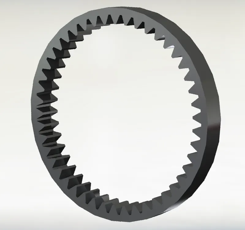
This internal spur gear has 46 teeth and the face width is 15 mm.
*All gears in this mechanism have the same gear module of 2.5 mm.
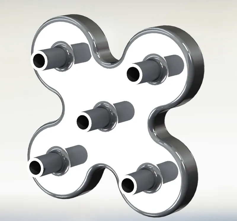
THE PLANET CARRIER:
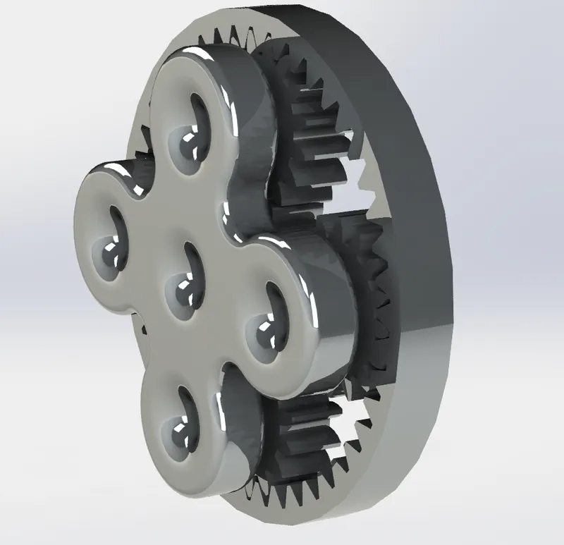
THE PLANETARY GEAR MECHANISM:

SIMULATION PARAMETERS:
- Rotary motor speed = 200 RPM constant
- The material is Steel (dry) for the carrier and Steel (greasy) for the gears.
- The simulation time is 10 RPM at 25 FPS with precise contact turned on.
SIMULATION RESULTS:
CASE 1: FIXED RING, INPUT SUN & OUTPUT CARRIER
When the ring gear is held stationary and the sun gear is used as the input, the planet carrier will be the output. This is the lowest gear ratio attainable with a planetary gear train.
The turns ratio relation for this setup is,
`T_c = (T_s*N_s)/(T_r + T_s)`
Therefore the gear ratio is,
`G_(c/s) = T_s/(T_s + T_r)`
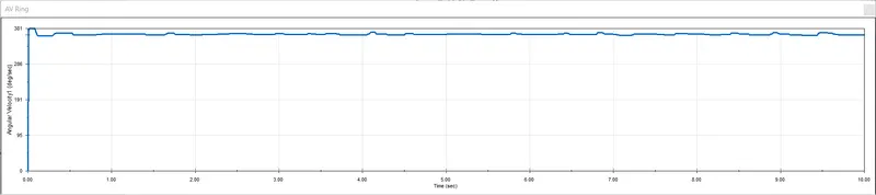
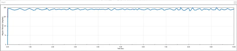
Angular velocity of Carrier v/s Time
Input velocity of the sun gear = `V_s` = 200 RPM = 1200 degrees/s
`G_(c/s) = 14/(14+46)` = 0.233
Output velocity of the planet carrier = `V_c` = `G_(c/s)*V_s` = 0.233*200 = 46.6 RPM = 279.6 degrees/s
CASE 2: FIXED SUN, INPUT RING & OUTPUT CARRIER
When the sun gear is held stationary and the ring gear is used as the input, again the planet carrier will be the output.
The turns ratio relation for this setup is,
`T_c = (T_r*N_r)/(T_r +N_s)`
Therefore the gear ratio is,
`G_(c/r) = T_r/(T_r + T_s)`
Angular velocity of Carrier v/s Time
Input velocity of the ring gear = `V_r`= 200 RPM = 1200 degrees/s
`G_(c/r) = 46/(14+46)` = 0.766
Output velocity of the planet carrier = `V_c` = `G_(c/r)*V_s` = 0.766*200 = 153.2 RPM = 919.2 degrees/s

CASE 3: FIXED CARRIER, INPUT SUN & OUTPUT RING
When the planet carrier is held stationary and the sun gear is used as the input, the ring gear will be the output. This is the reverse gear.
The turns ratio relation for this setup is,
`T_r = -T_s*N_s/N_r`
Therefore the gear ratio is,
`G_(r/s) = -T_s/T_r`
Angular Velocity of Ring gear v/s Time
Input velocity of the sun gear = `V_s` = 200 RPM = 1200 degrees/s
`G_(r/s) = -14/46` = -0.304
Output velocity of the ring gear = `V_r` = `G_(r/s)*V_s` = -0.304*200 = -60.8 RPM = -364.8 degrees/s