Suspension Geometry: Caster, Kingpin inclination and Scrub radius
To calculate the following geometric parameters by taking the given suspension hardpoints:
-
Caster.
-
Mechanical trail.
-
Kingpin inclination Angle.
-
Kingpin longitudinal offset.
-
Scrub radius
-
Kingpin lateral offset or spindle length
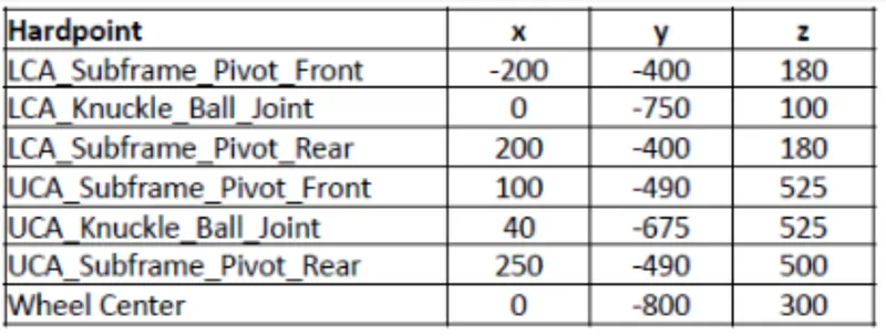
HARDPOINTS:
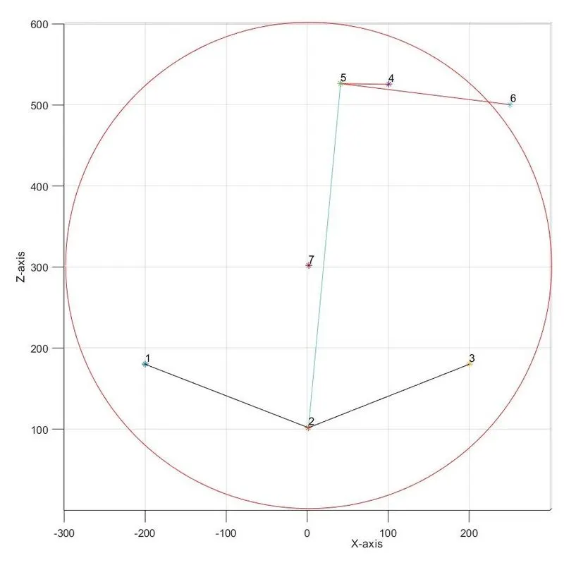
SIDE VIEW GEOMETRY:
| Parameter and its definition | Calculations | Diagram |
|
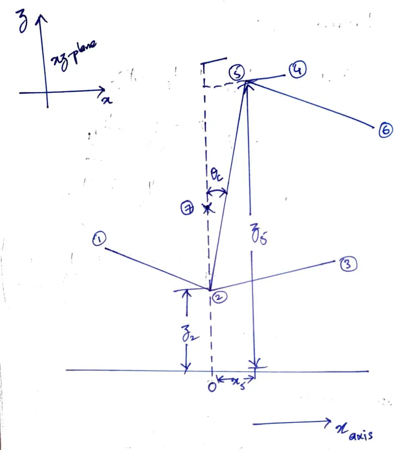
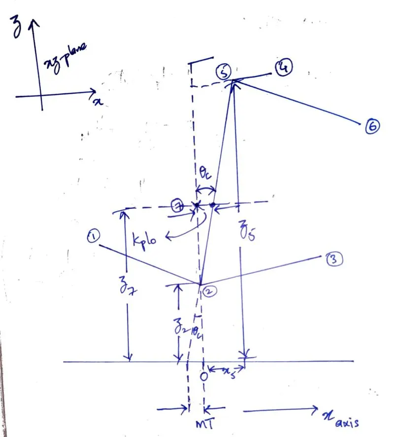
CASTER ANGLE: is the angle between the steering axis and the wheel centerline extending perpendicular from the contact patch, viewed in a vertical longitudinal plane (Side-view). |
`z_c = z_5 - z_2` `theta_c = tan^-1(x_5/(z_c))` `= tan^-1(40/(525 - 100))` Caster, `theta_c = 5.4 ^o` |
 |
|
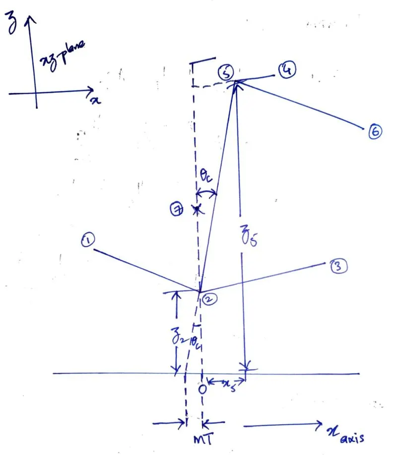
MECHANICAL TRAIL: It is defined as the distance between the intersection of the steering axis and the ground measured to the centre of the contact patch, viewed in the side-view. |
`MT = z_2*tan(theta_c) = 100*tan(5.4^o)` Mechanical trail length, `MT = 9.45 mm` |
 |
|
KINGPIN LONGITUDINAL OFFSET: It is defined as the distance offset of the steering axis along the x-axis when viewed from the side-view. |
`z_(kplo) = z_7 - z_2` `kplo = z_(kplo)*tan(theta_c) = (300 - 100)*tan(5.4^o)` Kingpin longitudinal offset, `kplo = 18.91 mm` |
 |
FRONT VIEW GEOMETRY:
| Parameter and its definition | Calculations | Diagram |
|
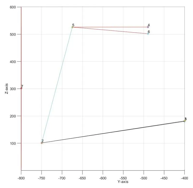
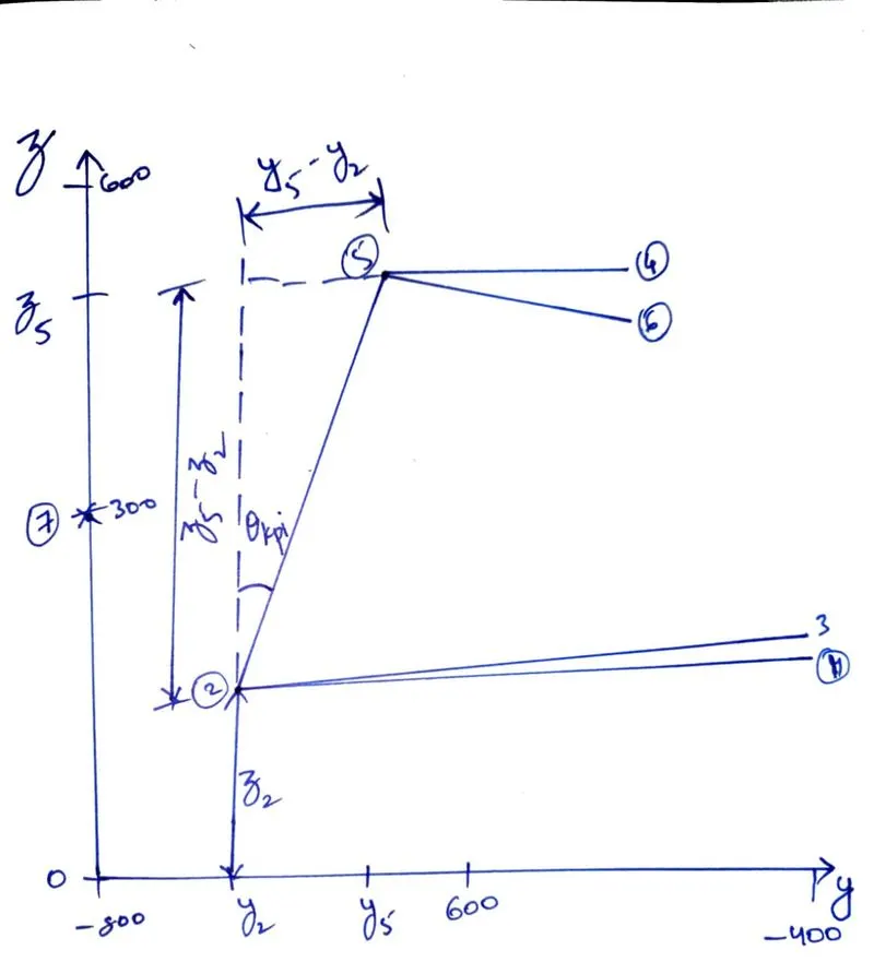
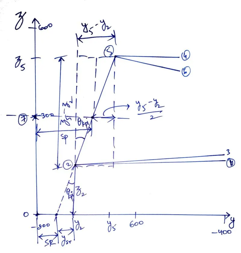
KINGPIN INCLINATION ANGLE: It is the angle between the steering axis and an axis extending perpendicular from the contact patch, viewed in the front plane. |
`y_(kp i) = y_5 - y_2` `theta_(kp i) = tan^-1(y_(kp i)/z_c) = tan^-1((-750 + 675)/(525 - 100))` Kingpin Inclination angle, `theta_(kp i) = 10.01^o` |
 |
|
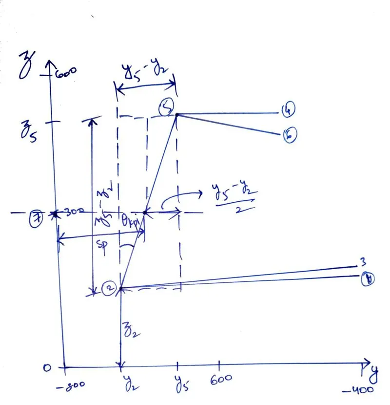
KINGPIN LATERAL OFFSET (or) SPINDLE LENGTH: The kingpin offset is the distance between the centre of the wheel and the crossing point of the kingpin axis and the wheel spindle axis. |
`sp = y_7 - y_5 + y_(kp i)/2 = -800 + 675 +(-750 +675)/2` Spindle length, `sp = -85.3 mm` |
 |
|
SCRUB RADIUS: It is the distance between the intersection of the steering axis and the ground measured to the centre of the contact patch, viewed perpendicular to the vertical-lateral plane (Front-plane). |
`y_(sr) = -z_2 * tan(theta_(kp i))` `SR = y_7 - y_(sr) - y_2 = -(100*tan(10.01^o)) - 800 + 750` Scrub radius, `SR = -32.35 mm` |
 |
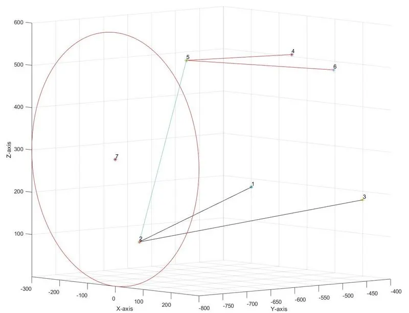
ISOMETRIC VIEW:
MATLAB CODE:
close all
clear all
clc

%%
x = [-200 0 200 100 40 250 0]; % All x-coordinates
y = [-400 -750 -400 -490 -675 -490 -800]; % All y-coordinates
z = [180 100 180 525 525 500 300]; % All z-coordinates

labels = {'1','2','3','4','5','6','7'};

for i = 1:length(x)
    hold on
    plot3(x(i),y(i),z(i),'*')
    text(x(i),y(i),z(i),labels{i},'VerticalAlignment','bottom','HorizontalAlignment','left')
end
    % Lower control arm
    plot3([x(1),x(2)],[y(1),y(2)],[z(1),z(2)],'color','k')
    plot3([x(2),x(3)],[y(2),y(3)],[z(2),z(3)],'color','k')
    % Upper control arm
    plot3([x(4),x(5)],[y(4),y(5)],[z(4),z(5)],'color','r')
    plot3([x(5),x(6)],[y(5),y(6)],[z(5),z(6)],'color','r')

    center = [x(7) y(7) z(7)]; normal = [0 1 0]; % Circle dimensions
    plotCircle3D(center,normal,z(7)) % Plotting wheel centre circle
    plot3([x(2),x(5)],[y(2),y(5)],[z(2),z(5)]) % Steering axis

    xlabel('X-axis')
    ylabel('Y-axis')
    zlabel('Z-axis')
    grid on

%% Side view (XZ Plane)
fprintf('SIDE VIEW GEOMETRYnn');
% Caster angle
z_c = z(5) - z(2);
caster = asind(x(5)/z_c);
fprintf('The caster is %f degrees.n',caster);

% Mechanical trail
mt_len = z(2)*tand(caster);
fprintf('The mechanical trail is %f mm.n',mt_len);

% Kingpin longitudinal offset
z_kplo = z(7) - z(2);
kplo = z_kplo*tand(caster);
fprintf('The kingpin longitudinal offset is %f mm.n',kplo);

%% Front view (YZ Plane)
fprintf('nFRONT VIEW GEOMETRYnn');
% Kingpin inclanation
y_kpi = y(5) - y(2);
kpi = atand(y_kpi/z_c);
fprintf('The kingpin inclanation angle is %f degrees.n',kpi);

% Scrub radius
y_sr = -z(2)*tand(kpi);
SR = -(y(7)-y_sr-y(2));
fprintf('The scrub radius is %f mm.n',SR);

% Kingpin lateral offset
sp = -(y(7) - y(5) + (y_kpi/2));
fprintf('The kingpin lateral offset or spindle length is %f mm.n',sp);
'plotCircle3D' FUNCTION CODE
function plotCircle3D(center,normal,radius)
    theta=0:0.01:2*pi;
    v=null(normal);
    points=repmat(center',1,size(theta,2))+radius*(v(:,1)*cos(theta)+v(:,2)*sin(theta));
    plot3(points(1,:),points(2,:),points(3,:),'r-');
end
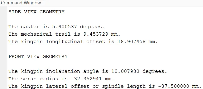
CODE SOLUTIONS:
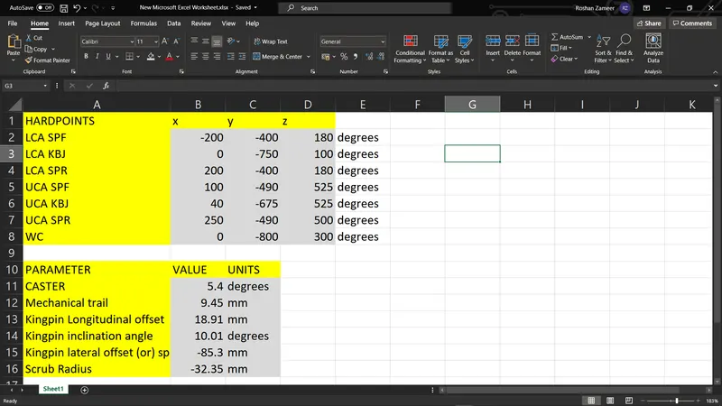
EXCEL SHEET:
Question 2: If the pneumatic trail is 25 mm and lateral force is 2000N, Calculate the restoring moment acting at the point where the kingpin intersects the ground in side view.
`PT_(l en) = 25 mm = 25 *10^-3 m`
`F_(y_i) = 2000 N`
Restoring moment, `M_R = F_(y_i)*(PT_(l en) + MT) = 2* (25 + 9.45) = 68.9 Nm`
Question 3: Suggest a hardpoint recommendation to change the sign of scrub radius that you calculated.
Decreasing the Kingpin inclination angle will change the sign of the scrub radius, this can be done by shortening the length of the LSA, i.e. moving the LSA knuckle ball joint away from wheel centre in the y-axis.