PISTON KINEMATICS MOTION SIMULATION USING SOLIDWORKS MBD
THE PISTON-CRANK ASSEMBLY:
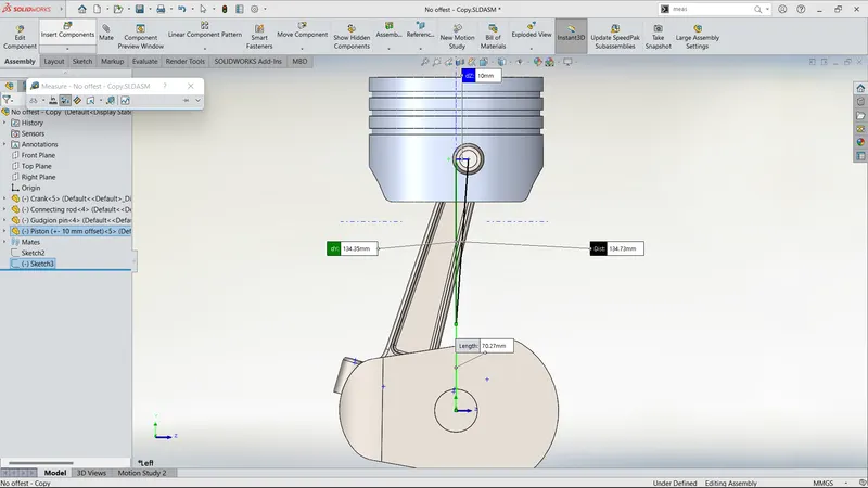
The piston is restricted to only the y-axis linear moment. The crank is restricted to the rotational axis at its central axis. The piston and the crank are further restricted by employing the gudgeon pin, the crankshaft assembly and the wrist-pin offset. Gravity is added.
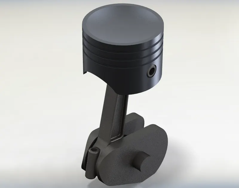
PISTON:
Material: 4032-T6 Aluminum Alloy
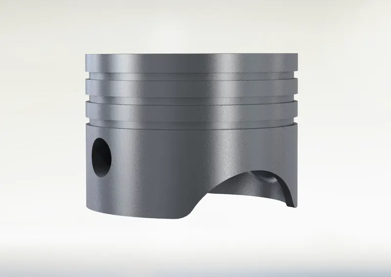
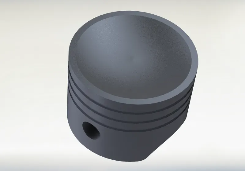
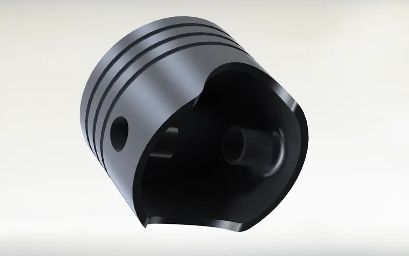
A piston is a component of reciprocating engines, reciprocating pumps, gas compressors, hydraulic cylinders and pneumatic cylinders, among other similar mechanisms. In an engine, its purpose is to transfer force from expanding gas in the cylinder to the crankshaft via a piston rod and/or connecting rod.
GUDGEON PIN:
Material: AISI 4340 Steel, Normalized
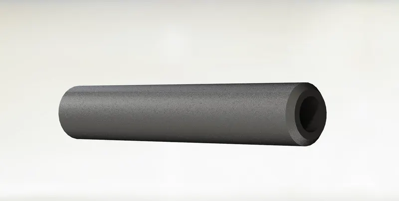
In internal combustion engines, the gudgeon pin connects the piston to the connecting rod and provides a bearing for the connecting rod to pivot upon as the piston moves.
CRANKSHAFT:
Material: AISI 4340 Steel, Normalized
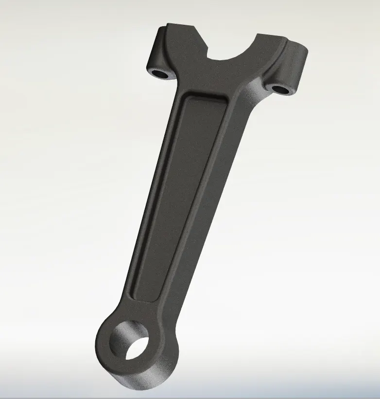
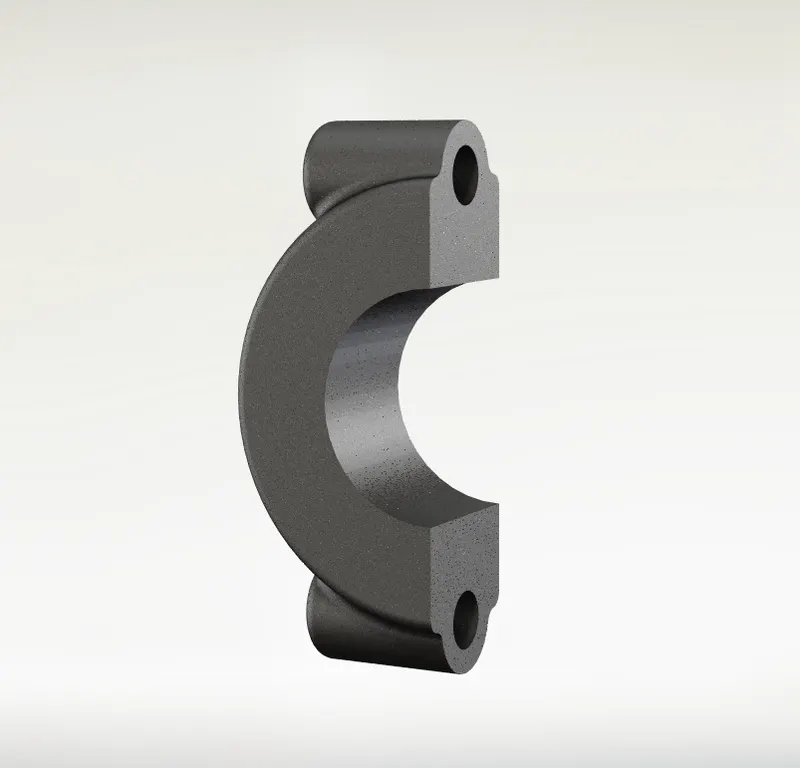
The crankshaft is essentially the backbone of the internal combustion engine. A crankshaft is a shaft driven by a crank mechanism, consisting of a series of cranks and crankpins to which the connecting rods of an engine is attached.
CRANK:
Material: AISI 4340 Steel, Normalized
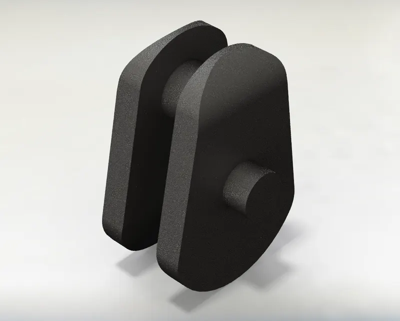
A part that is connected b/w the crankshaft and the flywheel. Essentially acts like a counterweight for the piston to reduce vibrations. It is typically connected to a flywheel to reduce the pulsation characteristic of the four-stroke cycle, and sometimes a torsional or vibrational damper at the opposite end, to reduce the torsional vibrations often caused along the length of the crankshaft by the cylinders farthest from the output end acting on the torsional elasticity of the metal.
MOTION ANALYSIS PARAMETERS:
Simulation time: 1 second
Crank speed: 2000 RPM
240 FPS
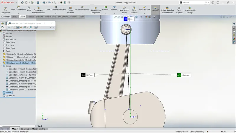
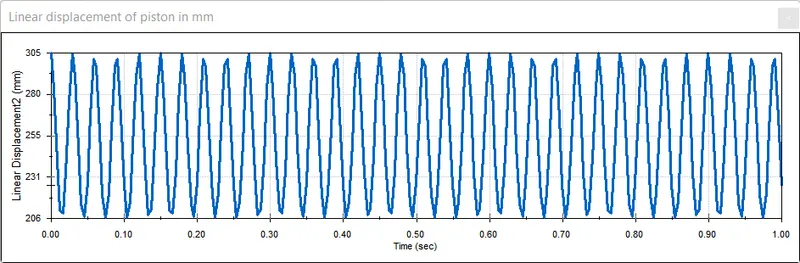
1. WRIST PIN OFFSET = 10 mm
The bore in the piston head is offset to 10 mm to the left of the piston axis.
2. WRIST PIN OFFSET: 0 mm
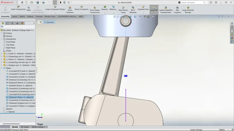
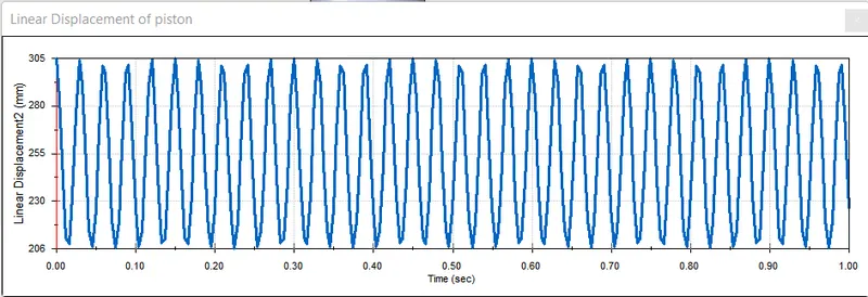
The bore in the piston head is not offset and it's at the centre.
3. WRIST PIN OFFSET = -10 mm
The bore in the piston head is offset to 10 mm to the right of the piston axis.
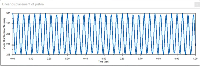
A superimposed plot of linear displacement of pistons with 0, -10 and 10 mm wrist pin offsets.
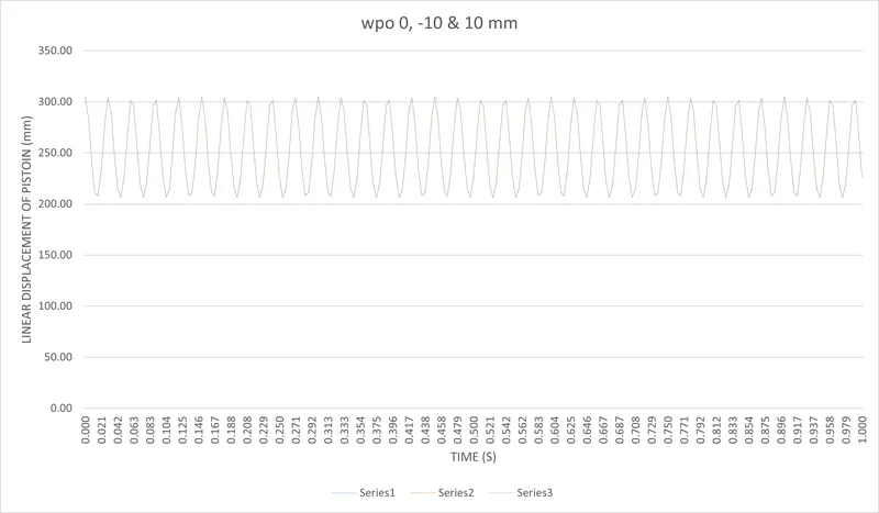
- The plots of each case are exactly overlapping each other as we are keeping the crank position the same for each case.
- There is only a minute change in the TDC and the BDC positions, so we are going to refer to the points on the excel sheet for comparison for peak positions of the piston.
- Time: 0.167 s to 0.179 s
-
TDC BDC Stroke length (mm) WPO +10 mm 304.08 208.53 95.55 WPO 0 mm 303.59 207.84 95.75 WPO -10 mm 304.08 207.94 96.14
-
- Time: 0.642 s to 0.658 s
-
TDC BDC Stroke length (mm) WPO +10 mm 301.74 206.18 94.56 WPO 0 mm 300.34 206.67 94.67 WPO -10 mm 301.32 206.36 94.96
-
- Comparing the data from these two plots, we can see that the stroke length of the piston assembly with wpo +10 mm < wpo 0 mm < wpo -10 mm
- Providing wrist pin offset to the cylinder assembly will eliminate vibrations when the piston is providing force and also decreases the compression forces in the connecting rod.