Wiring harness routing & packaging Rules Week 3 Challenge
Q1. Download P CLAMP cad data & define it as Electrical support using Electrical Part design Workbench. Define all the necessary properties.
Ans :
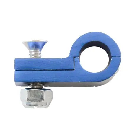
P clamps :
TE Connectivity (TE) P-Clamps provide a light, fast, and efficient harness solution to cable mounting. Our ten TE P-Clamp sizes cover the full cable diameter range of 21 standard P-Clamp sizes. Faster install times and lighter weight give TE P-Clamps a lower applied cost than standard P-Clamps.
It is the most user-friendly, versatile and robust P-Clamp for fastening and fixing cables, wires, pipes and hoses on the market. Especially for maintenance work, the Ratchet P-Clamp is the ideal solution: cables and wires can be replaced with ease, and without having to unscrew the product. All you need is a screwdriver to open the closure again.
Features
QUICK
• Faster installation time than standard AS21919 P-Clamps
• Quick-lock feature allows operators to quickly open and close the clamp as needed
• Minimizes risk of FOD (Foreign Object Debris) with hardware free locking mechanism
FLEXIBLE
• Separate mounting and clamping features allow flexible and modular assembly processes
• Highly engineered PEEK material maintains strength without the weight
• 10 TE P-Clamp sizes cover the same range as 21 standard AS21919 P-Clamp sizes
• Weight savings opportunities compared to standard AS21919 P-Clamps
ERGONOMIC
• Tool-less lock and unlock feature enables quick and comfortable harness installation and rework
• Operator comfort leads to faster cycle times
Applications
• Commercial Aviation
• Military Aerospace
• Military and Marine Vehicles
• Industrial Vehicles
• Rail
• Automotive
Defining all the necessary properties:
After downloading the cad data of p clamp from TE.com firstly we need to create a point.
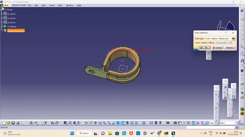
then we need to define the planes
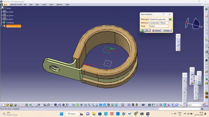
Now we need to define the support
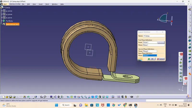
After defining the support
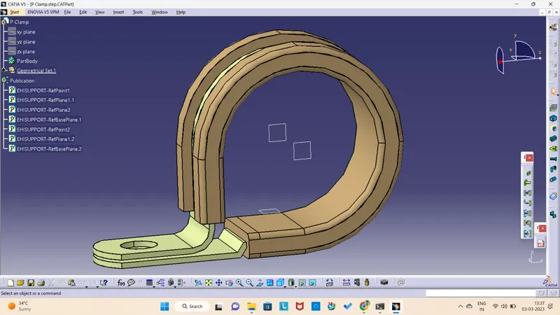
Q2. Download following Back shell cad data & define it as Electrical back shell using Electrical Part design Workbench. Define all the necessary properties.
Backshell :
What is a Back Shell. A Backshell is the rear portion of a connector, which is normally a separate section from the connector head, used to secure the cable via a clamp to the end of the connector.
When building a connector shell, the first parameter to consider is the type of backshell you need. The shell that a connector utilizes is driven by the connector's environment and use case. For example, connectors in naval control systems require humidity, water, and dust specifications, while shells used in aerospace applications may require radiation hardening and weight-limiting construction. Shell 'type' nomenclature varies across manufacturers, so be sure to reference a datasheet within your desired connector category and manufacturer to understand what various connector types are available.
Backshell Angle Options
Nearly all connector backshells―regardless of connector type, category, or manufacturer―come in at least three angle options. The backshell angle relates to how the conductor mates with its partnering connector, as shown in the image below. Varying connector backshell angles allow proper cable routing in confined spaces and generally come in straight (0°), 45°, and 90° varieties.

Coupling the Connector & Backshell
Common in the circular connector world, couplers connect the backshell to the actual connector and enable varying degrees of rigidity between the connector and the backshell. For example, connectors in high-vibration environments may require the use of a self-locking coupler to prevent the connector from accidentally decoupling. If accidental decoupling is not a concern, a simpler direct coupling allows the connector to thread to the backshell directly.
Tyco 1738312-1
After downloading the data from the given link we need to extract it and open in CATIA .
POINT DEFINITION
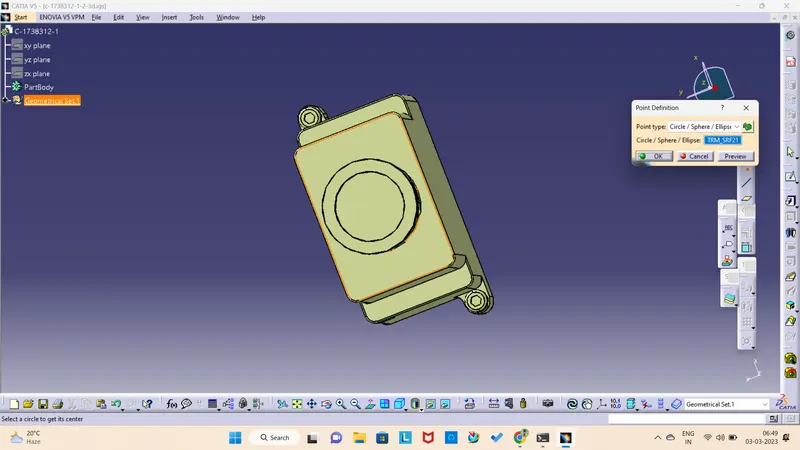
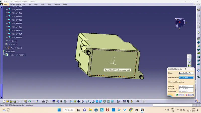
Defining backshell connection point
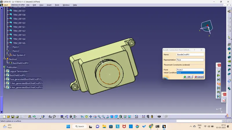
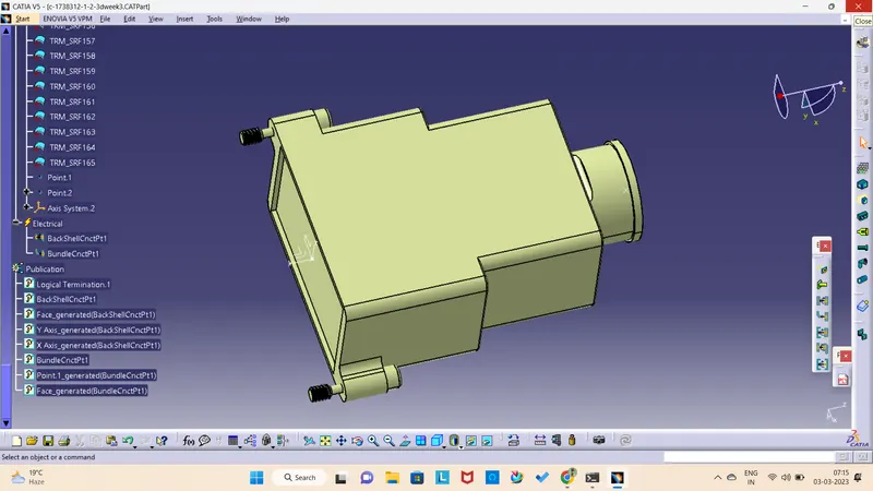
defining bundle connection point
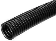
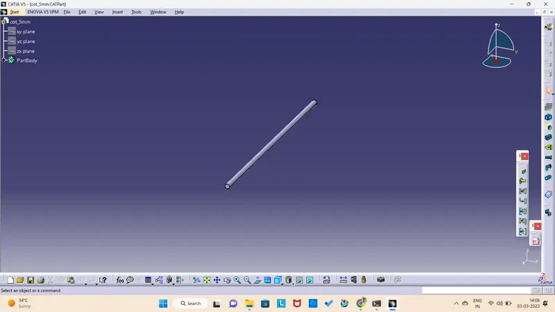
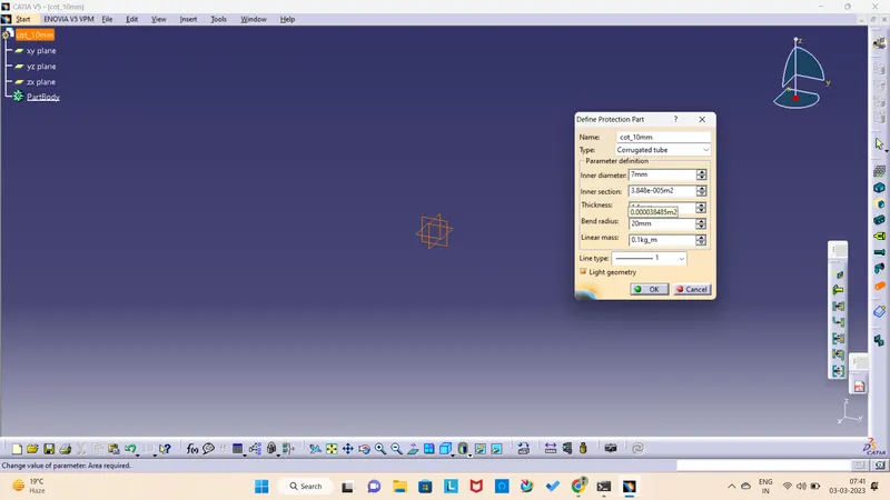
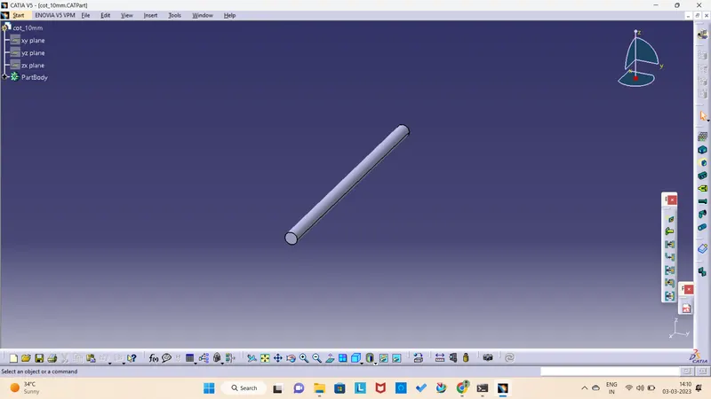
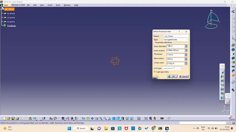
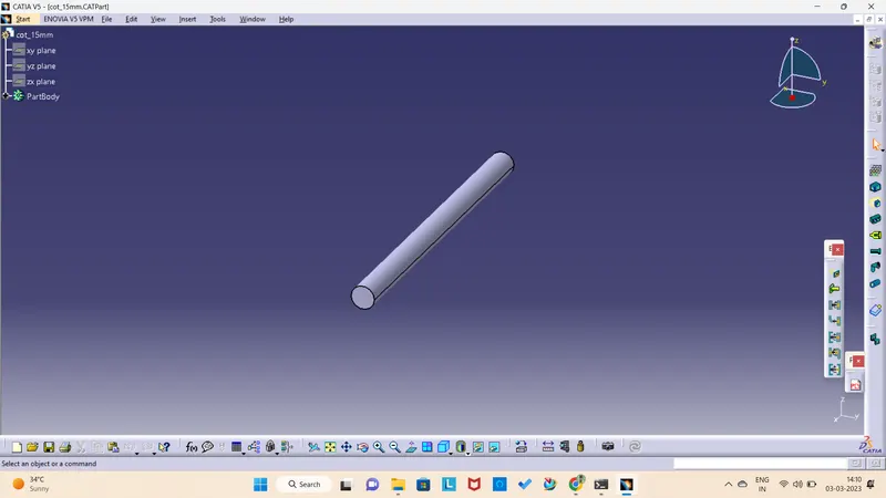
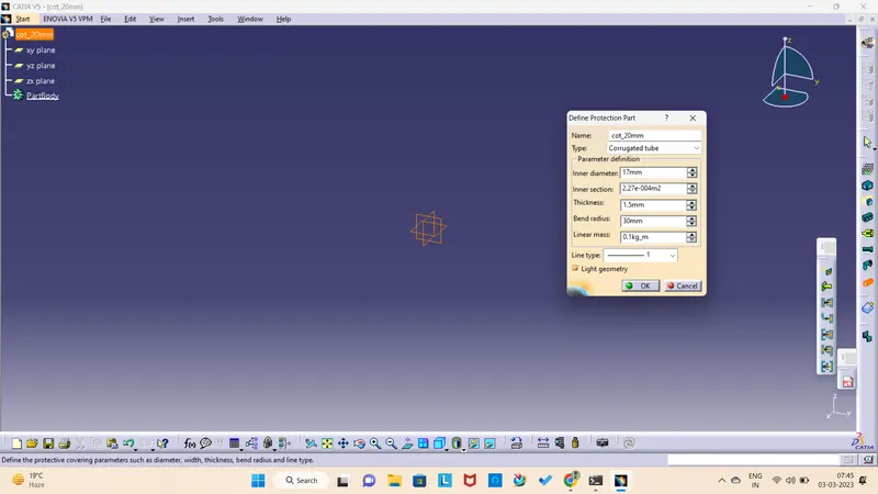
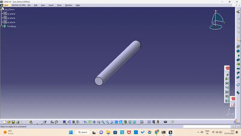
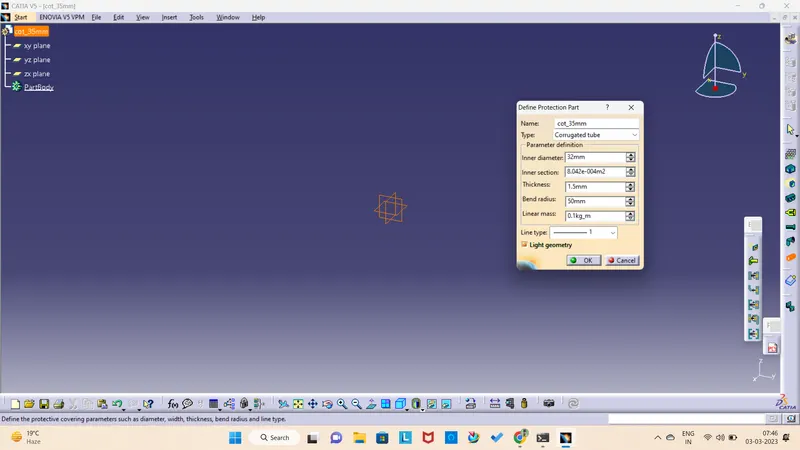
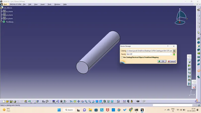
Q3. Create Following Corrugated tubes & Add them in Catalogue under “Slit COT” family.
|
Name |
ID (mm) |
OD (mm) |
Thickness (mm) |
|
15mm COT |
12 |
15 |
1.5 |
|
20mm COT |
17 |
20 |
1.5 |
|
35mm COT |
32 |
35 |
1.5 |
|
10mm COT |
7 |
10 |
1.5 |
|
5mm COT |
3 |
5 |
1 |