Project 1
Modeling a Double-Acting Actuator
Aim :
- Develop a double-acting actuator model using Simscape Multibody and Simscape components.
Objective :
- The mechanical system of the cylinder needs to be built using Simscape Multibody library components/blocks, and the hydraulic system needs to be modeled using Simscape library physical components.
Theory :
Cylinder Model
The schematics show the cylinder in three configurations: half-retracted, fully retracted, and fully extended.
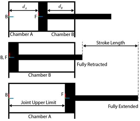
You can model the mechanical part of the system in Simscape Multibody. For example, to model the cylinder and piston, you can use the revolved solid (Simscape Multibody) and cylindrical solid (Simscape Multibody) blocks. To provide the translational degree of freedom for the piston, use a prismatic joint (Simscape Multibody) block. To easily calculate the lengths of the chambers A and B, you can attach the base frame (B) and follower frame (F) of the joint to the centers of the left inner surface of the chamber A and the left surface of the piston, respectively. Make sure that the Z-axes of the B and F frames are aligned and both point toward chamber B.
Using this convention, the length of the chamber A, dA, is the position output of the joint block, and the length of the chamber B, dB, equals the difference of the stroke length and dA. To ensure that the piston does not travel beyond the ends of the cylinder, you can specify the upper and lower position limits of the Prismatic Joint block.
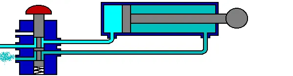
This figure shows the block diagram of the double-acting cylinder model described above. The example uses two translational mechanical converter blocks to model the chambers A and B of the cylinder. A Translational Multibody Interface block connects the Translational Mechanical Converter (IL) blocks to the Prismatic Joint block.
SIMULINK MODEL :
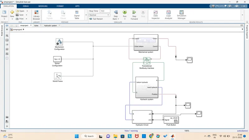
In this model i have used mechanism configuration block,solver configuration,world frame,hydraulic circuit,signal builder,translational multibody interface,mechanical subsystem and hydraulic subsystem.
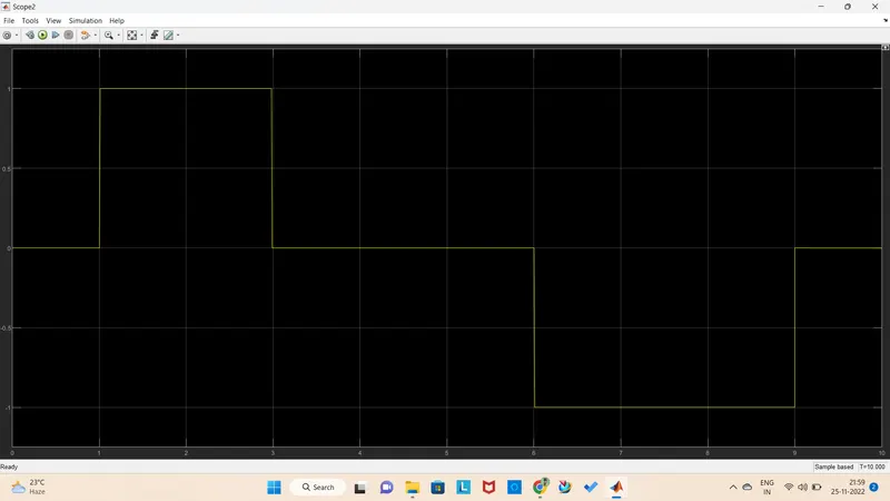
Here, we are giving input through signal builder as push button and getting the output from mechanism configuration.
MECHANICAL SUBSYSTEM :
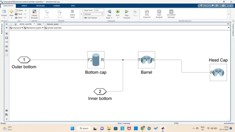
In this mechanical subsystem we are using two more subsystems they are cylinder assembly and piston assembly and we are using prism joint block.
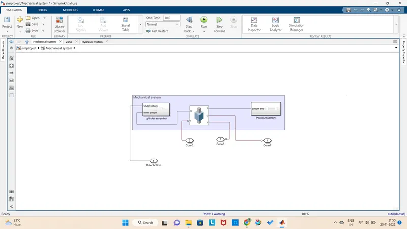
CYLINDER ASSEMBLY :
here we are using revolved solid blocks and brick solid block.
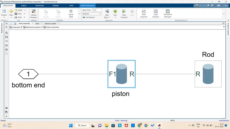
PISTON ASSEMBLY :
Here we are using two solid blocks to act ac a piston and rod.
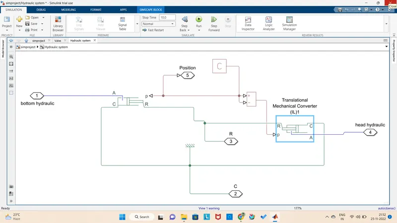
HYDRAULIC SUBSYSTEM :
Here we are using translational mechanical converter,ps constant, ps subtract and reference blocks.
INPUT SIGNAL THROUGH SIGNAL BUILDER :
REFERENCE DATA TAKEN FOR THIS PROJECT :
Cylinder assembly:
Bottom cap (solid) :
Geometry - Radius -0.1m
Length - 0.05m
Inertia - Density - 8050 kg/m^3
Graphic - Visual properties - color - [0.6 0.6 0.6]
Frames - Frame1 - right
Barrel (Solid) :
Geometry- Cross section - [0.08, 0.5/2; 0.08,-0.5/2; 0.1, -0.5/2; 0.1, 0.5/2] m
Inertia - Density - 8050 kg/m^3
Graphic - Visual properties - color - [0.6 0.6 0.6]
Opacity - 0.3
Head cap(Solid):
Geometry- Cross section - [0.04, 0.05/2; 0.04, -0.05/2; 0.1, -0.05/2; 0.1, 0.05/2] m
Inertia - Density - 8050 kg/m^3
Graphic - Visual properties - color - [0.6 0.6 0.6]
Prismatic joint :
State target - Specify position target - Priority - low
Value - 0
Internal mechanics - Equilibrium position - 0 m
Spring stiffness - 10 N/m
Damping coefficient - 1e6 N/(m/s)
Limit - Specify lower limit - Spring stiffness - 1e9 N/m
Damping coefficient - 1500 N/(m/s)
Specify upper limit - Spring stiffness - 1e9 N/m
Damping coefficient - 1500 N/(m/s)
Piston assembly :
Piston (Solid):
Geometry - Radius -0.08m
Length - 0.05m
Inertia - Density - 8050 kg/m^3
Graphic - Visual properties - color - [0.8 0.0 1.0]
Rod(Solid):
Geometry - Radius -0.04m
Length - 0.5m
Inertia - Density - 8050 kg/m^3
Graphic - Visual properties - Diffuse color - [0.9 0.9 0.9]
Frames - Frame1 - left
Hydraulic System:
Bottom chamber- Interface cross sectional area- pi*0.08^2 m^2
Dead volume- 1e-4 m^3
Fluid dynamic compressibility- Off
Head chamber- Interface cross sectional area- pi*(0.08^2-0.04^2) m^2
Dead volume- 1e-4 m^3
Fluid dynamic compressibility- On
Initial liquid pressure- 4e6 Pa
PS constant- Constant- 0.45 m
OUTPUT SCOPE FROM MECHANICS EXPLORER :
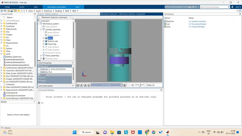
Conclusion :
Now we can see the output from the mechanism configuration that piston movement for the given input .