Week - 4
- Implement control logic of a “washing machine” using Stateflow as per given sequence:
- If the power supply is available, the system gets activated
- If the Water supply is not available, stop the process & indicate through LED
- Soaking time should be 200s followed by Washing time of 100s.
- Then rinsing happens for next 20s & dryer runs for 50s
After all the processes have completed turn on the finished LED
Ans:
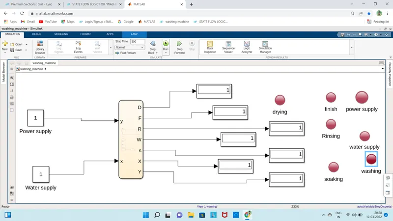
- In this stateflow chart we have used two inputs.
- One is power supply input(x) and water supply input(y) .
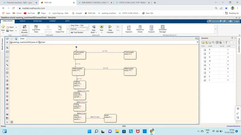
- As shown in the chart if power supply x==1 then it will go to the water supply otherwise the process will not start and takes the condition of x<=0.
- In water supply also it follows same process if water supply y==1 then it will go to the soaking process otherwise it will stop the process there itself and takes the condition of y<=0.
- After successful inputs of the chart wehave to do soaking process and after 200 secs washing process then after 100 secs rinsing process after 20 secs drying and after 50 secs the process will be finished.
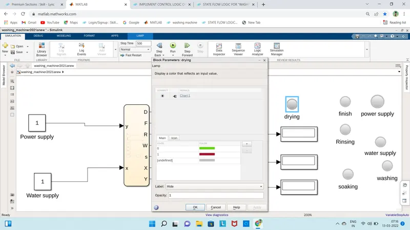
- As shown above the block parameters are defined .
- when the process is going on then green light will blow and after finishing red light will blow.
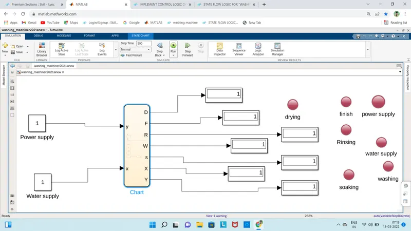
- by changing the values of stop time and running it we will get individual lights and results .
this will be the final result of control logic of a “washing machine” using Stateflow as per given sequence.
2. Make a Simulink chart for the “Gear shift” logic as per below conditions:
Speed Range(kmph) Gear
0 to 15 1
16 to 25 2
26 to 40 3
41 to 60 4
Above 61 5
Give speed input while the simulation is running & display the gear number.
Ans:In this speed is our input and gear is the ouput
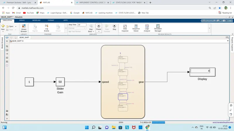
according to the control logic we have created a chart and block diagram as shown below

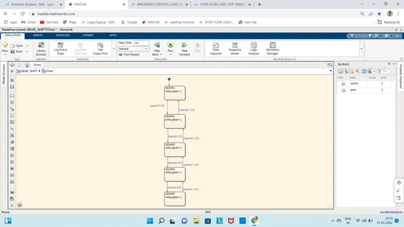
- we have used slidergain block to vary the speeds according to our desired input .
- in this we can slide the radar to increase or decrease the speeds.
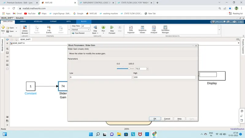
- when we give the value between 0 and 15 and run it then it will display the output as 1
- if the value is between 16 and 25 it will dispaly as 2 and yhe process continues according th control logic .
- for example we are giving input of 50 speed then we will get the output as 4th gear that as shown in below pic