Section Modulus calculation and optimization
SECTION MODULUS CALCULATION AND OPTIMIZATION
CONCEPT : Brief explanation about Section Modulus
Section modulus is a geometric property for a given cross-section used in the design of beams or flexural members. Other geometric properties used in design include area for tension and shear, radius of gyration for compression, and moment of inertia and polar moment of inertia for stiffness.
For general design, the elastic section modulus is used, applying up to the yield point for most metals and other common materials.
The elastic section modulus is defined as S = I / y, where I is the second moment of area (or area moment of inertia, not to be confused with moment of inertia) and y is the distance from the neutral axis to any given fibre. It is often reported using y = c, where c is the distance from the neutral axis to the most extreme fibre, as seen in the table below. It is also often used to determine the yield moment (My) such that My = S ⋅ σy, where σy is the yield strength of the material.
S = I / Y , where,
S = section modulus,
I = moment of inertia of the section about the bending axis
Y = Distance between the neutral axis or centroidal axis and extreme end of the object.
Also, Y = C /2 , where,
C = the distance to remotest element, from the neutral axis or centroidal axis.
Though generally section modulus is calculated for the extreme tensile or compressive fibres in a bending beam, often compression is the most critical case due to onset of flexural torsional (F/T) buckling. Generally (except for brittle materials like concrete) tensile extreme fibres have a higher allowable stress or capacity than compressive fibres.
In the case of T-sections if there are tensile fibres at the bottom of the T they may still be more critical than the compressive fibres at the top due to a generally much larger distance from the neutral axis so despite having a higher allowable stress the elastic section modulus is also lower. In this case F/T buckling must still be assessed as the beam length and restraints may result in reduced compressive member bending allowable stress or capacity.
There may also be a number of different critical cases that require consideration, such as there being different values for orthogonal and principal axes and in the case of unequal angle sections in the principal axes there is a section modulus for each corner.
For a conservative (safe) design, civil structural engineers are often concerned with the combination of the highest load (tensile or compressive) and lowest elastic section modulus for a given section station along a beam, although if the loading is well understood one can take advantage of different section modulus for tension and compression to get more out of the design. For aeronautical and space applications where designs must be much less conservative for weight saving, structural testing is often required to ensure safety as reliance on structural analysis alone is more difficult (and expensive) to justify.
SECTION MODULUS STUDY: Use the Section from your Hood design and calculate the section modulus.
BEFORE OPTIMIZATION:
- To do the section inertia analysis first we need a section of our hood assembly design.
- For the section of hood assembly we need to activate hood assembly in assembly navigator.
- Then goto CURVE and select INTERSECTION CURVE option, in that select entire assembly option and body faces option then select hood outer panel and hood inner panel.
- By using mirror plane we will get a curve.
- Then we need to create a datum plane.
- Now,by using PROJECT CURVE option and by selecting intersection curve we will get projected curve.
- Now we need to delete the inner curve by using QUICK TRIM option and need to connect the gaps using QUICK EXTEND option for a closed curve.
- Then goto ANALYSIS and select SECTION INERTIA ANALYSIS then we will get the below result

- here moment of inertia max is 8.217e+05 [mm^4] and moment of inertia min is 6.016e+03 [mm^4].
- Now we need to calculate the distance (Y).
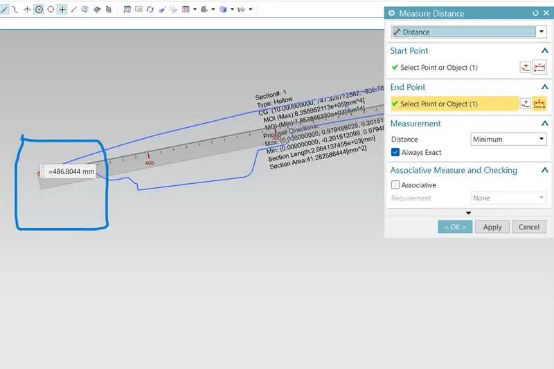
- Y= total distance/2 =486.8/2 =243.4 mm
- now section modulus =moment of inertia(min)/Y = 6.016e+03 [mm^4]/243.4mm = 24.7 mm^3.
AFTER OPTIMIZATION
Here i am offsetting the curve by 5mm and doing the same procedure to get a closed curve .
Now we are getting
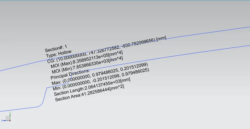
moment of inertia max = 8.35895e+05[mm^4] and
moment of inertia min = 7.85386e+03[mm^4].
Now calculating the section modulus =moment of inertia min / y
= 7853 mm^4 / 243.4 mm
= 32.2 mm^3
CONCLUSION:
Here section modulus after optimization is more than before optimization.
By increasing cross sectional area, moment of inertia and section modulus are increasing.
From this we can notice that by increasing cross sectional area we can increase strength and stiffness of the model