Aim: Study of Energy Management Strategy using Battery, Ultracapacitor and Fuel Cell
Objective:
The output of the model should be the power request from
1. UC
2. Fuel Cell
3. Battery
Introduction:
Fuel cell vehicles have been considered as the next generation of automobiles since they could be the
solution for a clean, safe and high efficiency transportation. However, their commercialization and
mass production are restrained by the durability and the short lifetime of fuel cells compared to
internal combustion engine vehicles. The hybridization with a high power density sources such as ultra-
capacitors or batteries relieves the fuel cell from sudden power demands and therefore increase its
lifetime.
In the past few decades, fossil fuels have been widely used as the power source of ordinary internal
combustion engine, which has caused lots of negative effects, such as the gradual depletion of oil
resources, the deepening of the global energy crisis, the aggravation of air pollution, and the rise of
global temperature. Therefore, a series of new energy vehicles emerge at a historic moment. Many
studies have been done on fuel cell vehicles for their convenient, efficient, and clean energy utilization.
A fuel cell is the main power source, and the battery or ultra-capacitor is the auxiliary power source
to provide power for the fuel cell hybrid vehicle (FCHV) when FCHV is in operation. This hybrid
power distribution method has been widely used in FCHV. Therefore, the hybrid power distribution
mode of FCHV has been the focus of a lot of research, in which the energy management strategy
of controlling the fuel cell system and energy storage system are the key topics.
Depending on how the necessary power is obtained, a minimization of the hydrogen consumption
can be achieved: the Energy Management Strategies (EMSs) are algorithms which determine
at each sampling time the power generation split between the fuel cell system (FCS) and the energy
storage system (ESS) in order to fulfil the power balance between the load power and the power source.
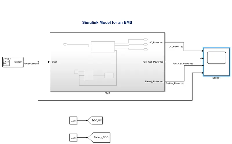
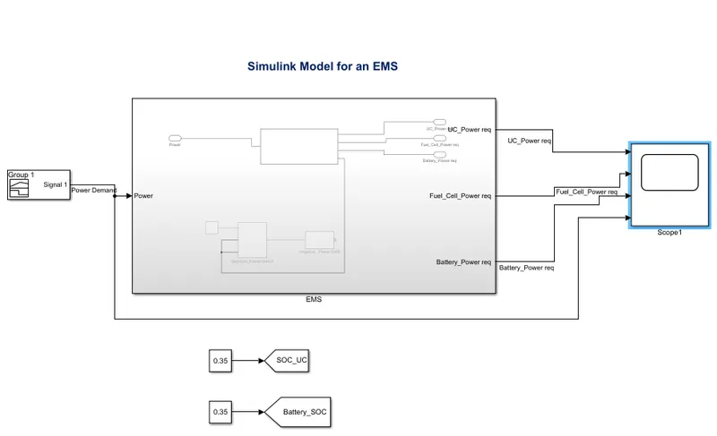
Simulink Model:
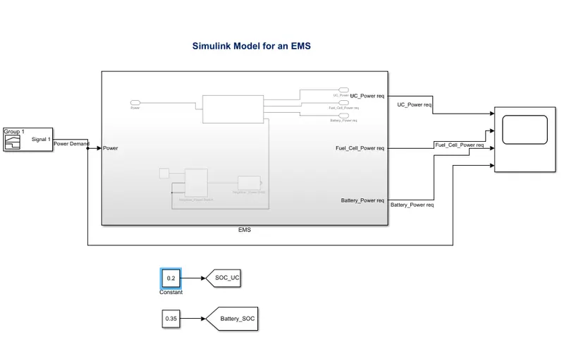
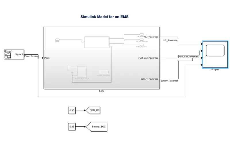
Figure 1
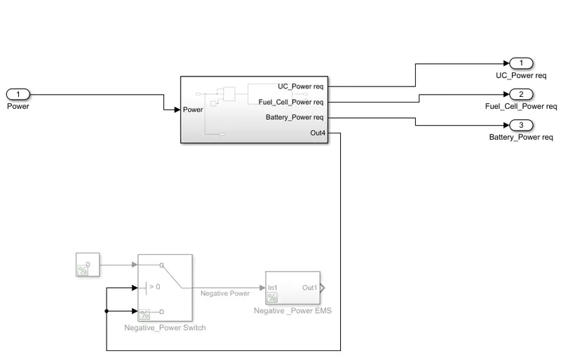
EMS:-
Figure 2
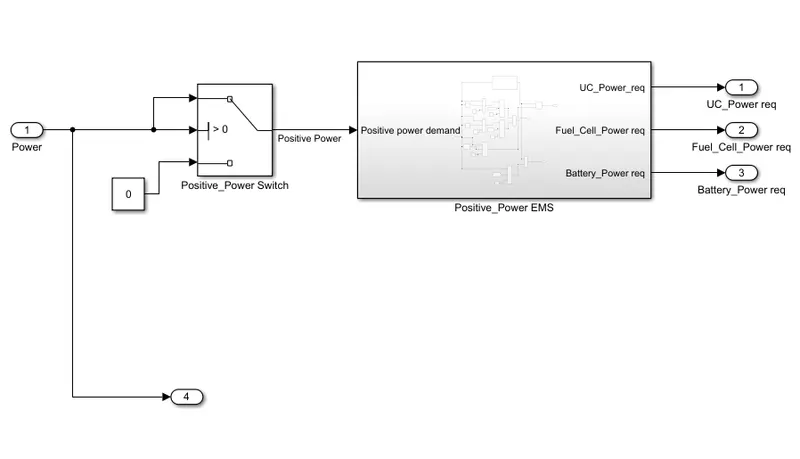
Subsystem:-
Figure 3
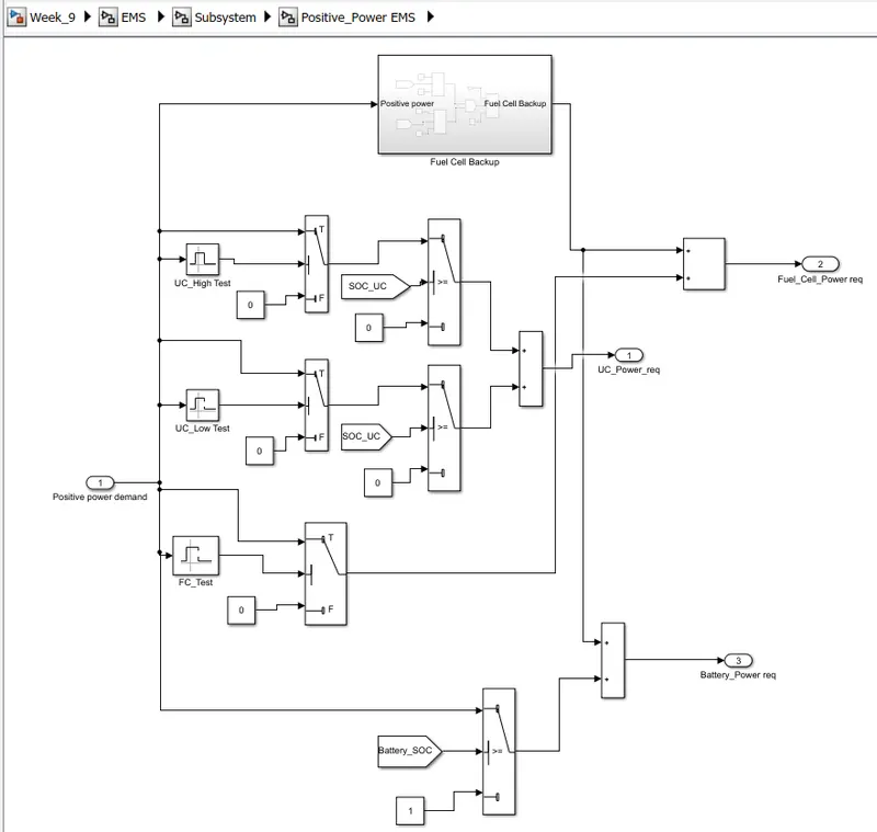
Positive_Power EMS :-
Figure 4
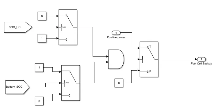
Fuel Cell Backup model:-
Figure 5
Blocks used in this Simulation:
1. Signal Builder block
2. Constant Block
3. Subsystem
4. Goto
5. From
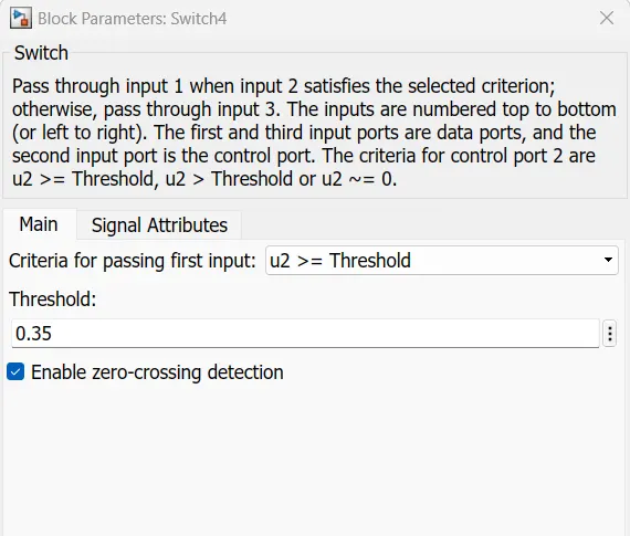
6. Switch
7. Add
8. Inport
9. Outport
10. Interval Test
11. AND Gate
12. Scope block
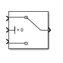
1. Switch Block
When a case is true, MATLAB executes the corresponding statements and then exits the switch
block. The otherwise block is optional and executes only when no case is true.
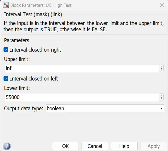
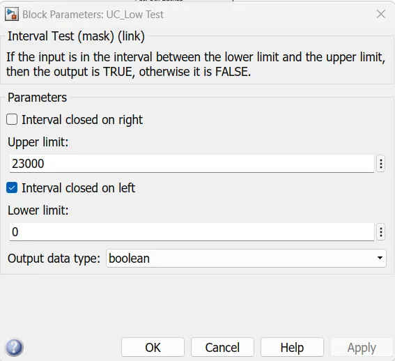
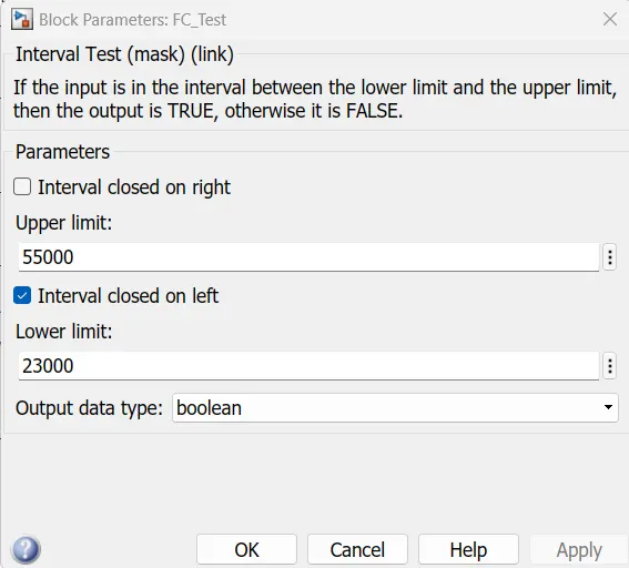
2. Interval Test
If the input is in the interval between the lower limit and the upper limit, then the output is TRUE,
otherwise it is FALSE.
3. Goto
The Goto block passes its input to its corresponding From blocks. The input can be a real- or
complex-valued signal or vector of any data type.
4. From
The From File block reads data into a Simulink ® model from a MAT file and provides the data
as a signal or nonvirtual bus at the block output. We can load data from a MAT file that is on or off
the MATLAB ® path. A model can contain multiple From File blocks that load data from the same
MAT file.
5. Scope
Results are observed with the help of this block.
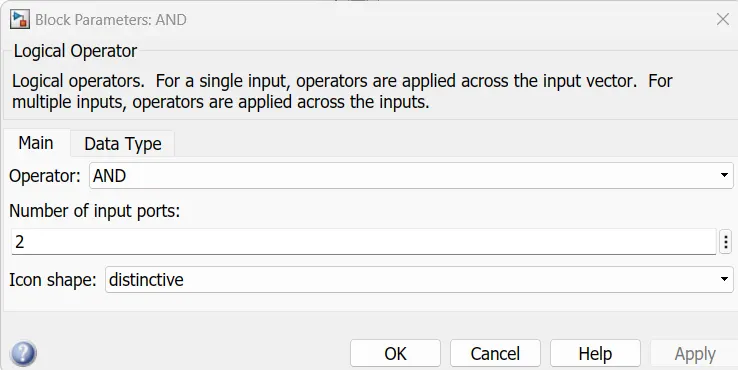
6. AND logical operator
The simulation time is set to a 598 sec.
Case 1:
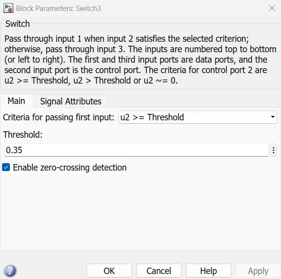
When, SOC_UC = 0.35
Battery_SOC = 0.35
Simulink Model will be,
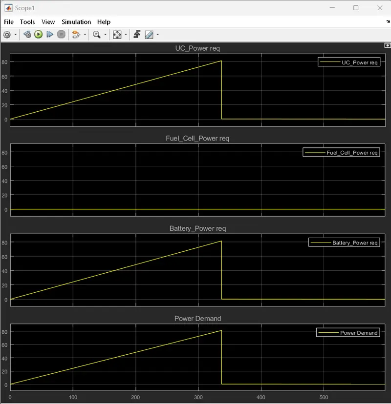
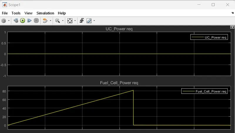
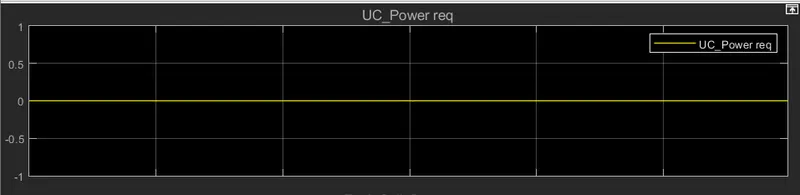
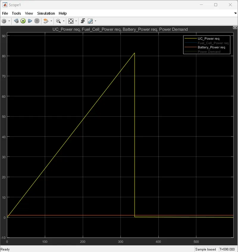
From Scope result it can be conclude that Fuel cell power is zero as UC is above or equal to 35%
during this Ultracapacitor is able to provide require amount of power.
Case 2:
When SOC is less than 35%
During this case we can see that UC are not able to provide power. This time Power demand can be
fulfiiled by Fuel Cell.
Case 3:
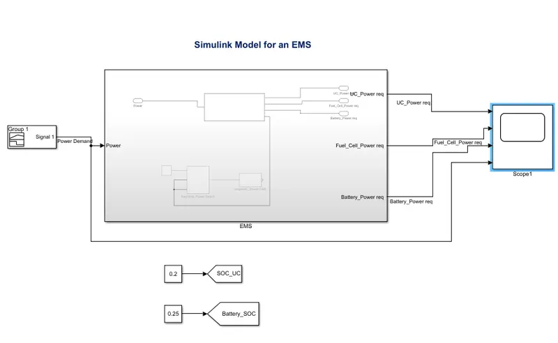
If Both the Battery_SOC and SOC_UC is less than 35% the output is as shown below.
Case 4:
When Battery_SOC is less than 35% and SOC_UC is equal to or greater than 35%.
Then simulink model will be,
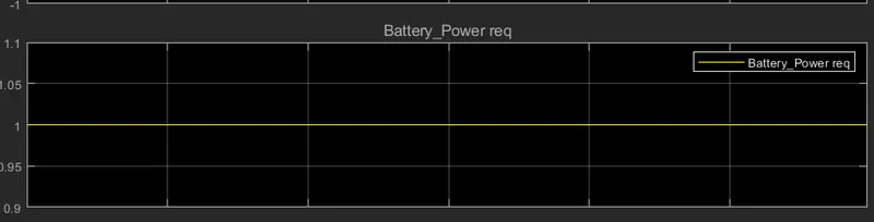
From this result it can be seen that during this condition Battery not able to provide power during
this.
From the above all cases we have noticed that Fuel cell acts as a backup when ultracapacitor is fails
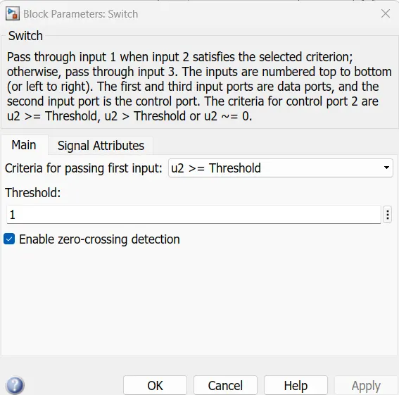
to provide power then that power can be provide by fuel cell. criterion must be such that to provide
power by battery or UC, SOC must be greater than or equal to 35% then only they can fulfill power
requirement.
Link:
Kindly open attached Simulink file with the help of MATLAB/Simulink.
Conclusion:
Completion of the energy management strategy model with battery, UC and fuel cell for the positive
power is achieved. With the help of different cases actual behaviour of UC, Battery and Fuel cell is
observed.