Week-11 Challenge: Braking
Aim 1: To calculate the energy required for braking.
Objective: To create a drive cycle and to calculate the total braking
energy required.
Explaination:
Let us consider the following drive cycle,
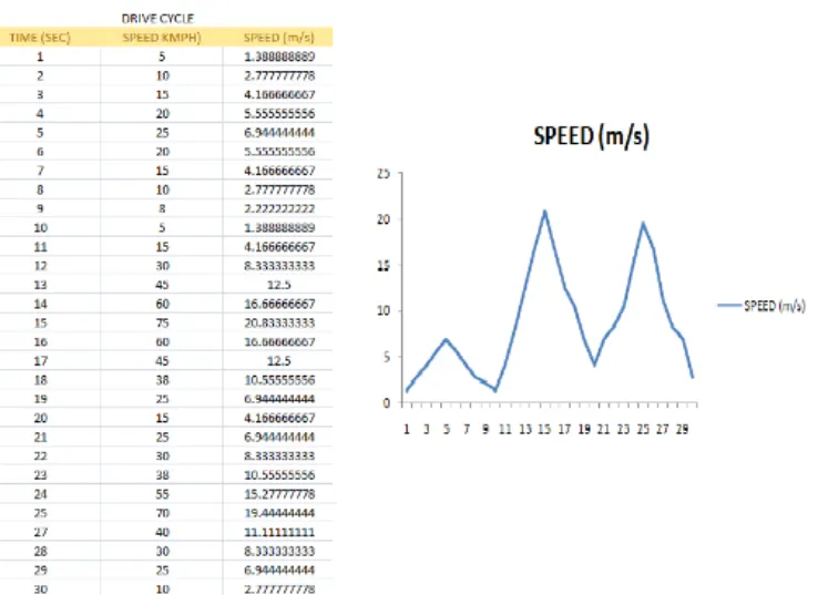
Here,
Mass of the vehicle = 1000 kg.
a) For the first 10 seconds,
Top speed after acceleration , V2 = 25m/s
Lowest speed after deceleration, V1 = 5m/s
Braking energy required,
BE1 = 1/2 * m * (V2-V1)^2
BE1 = 1/2 * 1000 * (6.94 - 1.38)^2
BE1 = 15.5 KW
b) For the next 20 seconds,
BE2 = 1/2 * m * (V2-V1)^2
BE2 = 1/2 * 1000 * (20.83 - 4.16)^2
BE2 = 138.9 KW
c) For the next 30 seconds,
BE3 = 1/2 * m * (V2-V1)^2
BE3 = 1/2 * 1000 * (19.44 - 2.77)^2
BE3 = 138.9 KW
Total Braking Energy Required,
BE(total) = BE1 + BE2 + BE3
= 15.5 + 138.9 + 138.9
BE(total) = 293.3 KW
Conclusion:
For the driving cycle, the braking energy required is 293.3 KW.
Aim 2: Why electric motor can’t develop braking torque at high speed similar to starting?
How electric and mechanical brakes are coordinated?
Answer:
What is electric braking?
Electric braking is a method of braking in which a DC voltage is applied to the stationary
winding of an electric motor after the AC voltage is removed. Electric braking is also known
as DC injection braking.
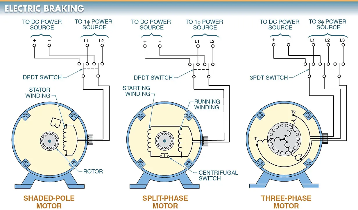
In electrical braking, the motor is made to work as a generator. So that it produces a ' -ve '
slip and negative torque i.e., braking torque. The motor can easily made to work as a
generator by suitably changing the electrical connections of the motor.
What is the torque of an electric motor?
Torque describes and classifies electrical motors. Torque is the turning force through
a radius - with the units Nm in the SI-system and the units lb ft in the iperial system.
The torque developed by an asynchronous induction motor varies when the motor
accelerates from zero to maximum operating speed.
What is break down torque in power steering?
Break-down torque is the highest torque available before the torque decreases when
the machine continues to accelerate to working conditions. Full load torque or braking
torque is the torque required to produce the rated power of an electrical motor at full
load speed of the motor.
Braking of electrical motors:
Whenever an electric motor is disconnected from the supply of the driving motor
gradually decreases and become zero after a few minutes. Braking includes rapid
stopping of the electric motor, holding the motor shaft to a specific position, maintaining
the speed to a desired value of preventing the motor from over speeding.
How braking works
During the braking process, the energy can change its flow between the source
and load. In this period, the motor drive acts as a generator, which pumps the
energy back to the electric supply. The complete operational cycle of an electric
motor in highly dependent on braking method.
Types of Braking
1] Mechanical braking
2] Electrical braking
1] Mechanical braking
The mechanical braking systems powers the hand brake or emergency brake. It
is the type of braking system in which the brake force applied on the brake force
applied on the brake pedal is carried to the final brake drum or disc rortor by
various mechanical linkages like cylindrical rods, fulcrums, springs etc. In order
to stop the vehicles.
Mechanical brakes were used in several old automobile vehicles but they are
archanic nowadays due to their less effectiveness.
Types of brakes:
1] DISC BRAKE
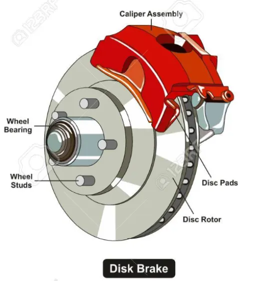
The disc brake is a mechanism for slowing or stopping the rotation of a wheel
from its motion. A disc brake is normally made of caste iron, but in some cases
it is also made of composites such as a carbon-carbon ceramic-matrix composites.
This is linked to the wheel and/or the axle. To stop the wheel, friction material
in the form of brake pads is forced against both sides of the disc. Friction caused
on the disc wheel will slow or stop.
2] DRUM BRAKE
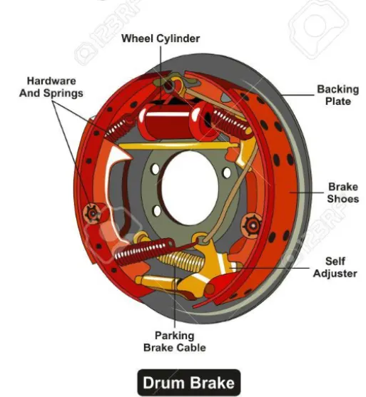
A drum brake is a traditional brake in which th friction is caused by sets of shoes
or pads that press against a rotating drum-shaped part called a brake drum.
The term \"drum brake"\ usually means a brake in which shoes press on the
inner surface of the drum. Where the drum is pinched between two shoes ,
similar to a standard disc brake, it is sometimes called a \"pinch drum brake"\,
although such brakes are relatively rare.
2] Electrical braking
In electrical braking, the motor is made to work as a generator. So that it
produces a negative slip and negative torque i.e.braking torque. The motor
can easily made to work as a generator by suitably changing the electrical
connections of a motor. Whether mechanical or electrical braking, of the
drive should be such as to stop the motor at a specified point of time, for
safety reason.
Types of Electrical Braking systems:
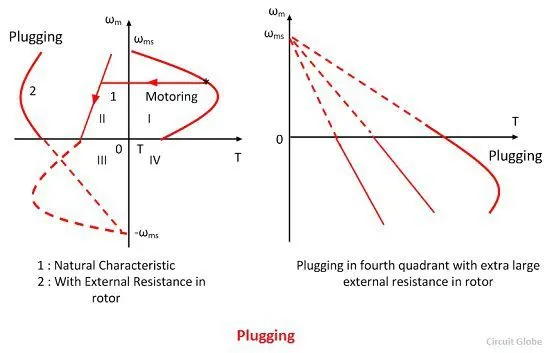
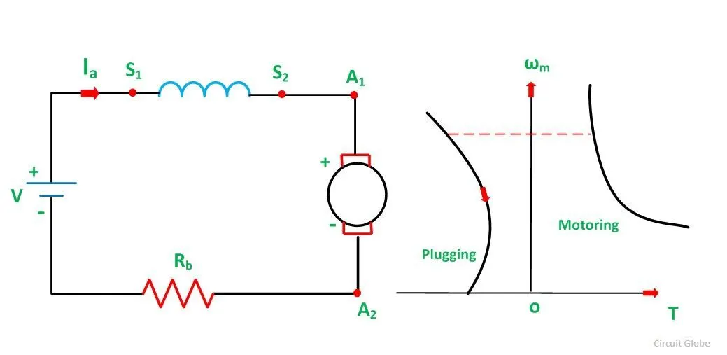
1] Plugging
a] This is the simplest type of electric braking.
b] In this method, the torque of the motor is reversed.
c] It makes the motor and the driven machine to standstill condition.
d] A special device is required to cut off the supply as soon as the motor
comes to rest.
e] The plugging braking method can be applied to AC and DC motors.
2] Dynamic Braking
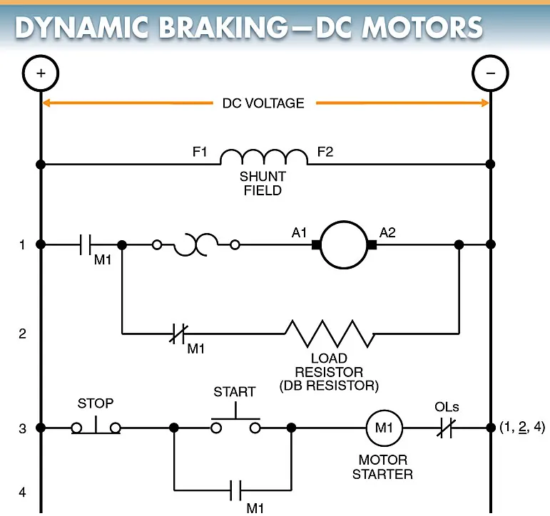
a] In this method of braking, the motor is disconnected from the supply.
b] Then operated as a generator driven by the kinetic energy of the rotor
and the load.
c] Thus the kinetic energy of rotation is converted into electrical energy.
d] This electrical energy is dissipated in the external resistance connected
across the motor at the braking instant.
e] The advantage of dynamic braking is that there is no energy is required
from the supply to brake the motor.
f] The dynamic braking method can be applied to brake DC motors, induction
motors and synchronous motors.
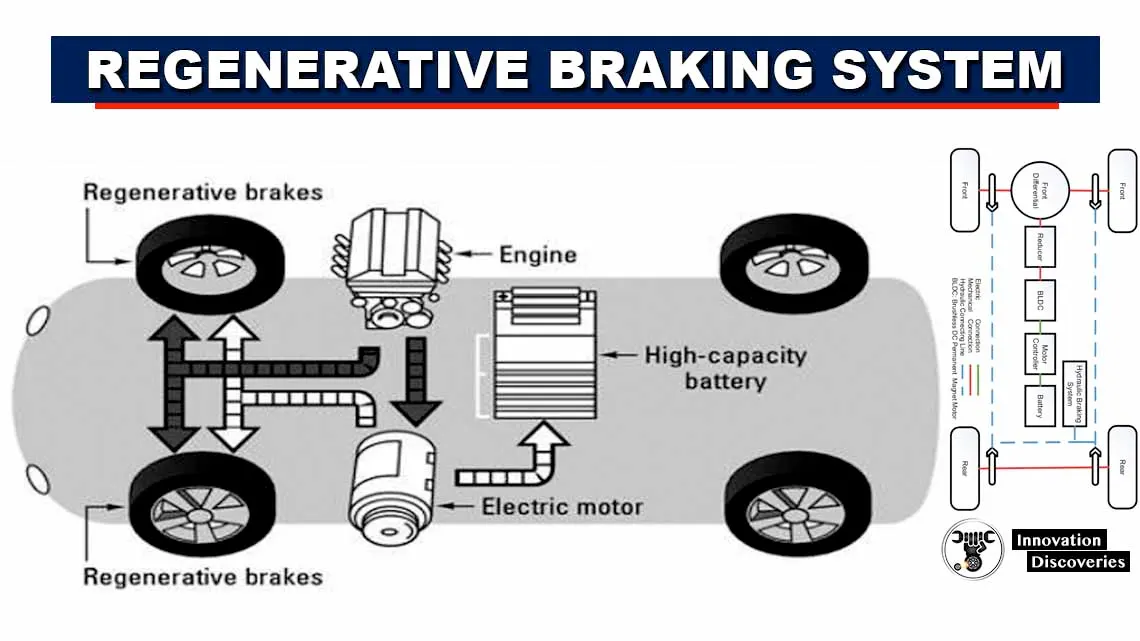
3] Regenerative Braking
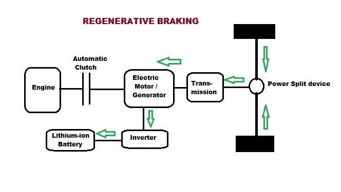
a] In the regenerative braking method the motor is not disconnected from the
supply.
b] It remains connected to it and feeds back the braking energy or it kinetic
energy to the system.
c] As no energy is wasted in this method and it is supplied back to the system,
thus overall energy is saved.
d] Thus regenerative braking is better than plugging and dynamic braking.
e] This type of braking is used in traction whenever the train runs on down.
f] The regenerative braking is applied to DC shunt motor, series motor and
3-phase induction motor.
Mechanical Braking Vs Electrical Braking:
Mechanical Braking Electrical Braking
1. The energy of the rotating parts is 1. The energy of the rotating parts can be converted into
wasted as heat in friction. electrical energy which can be utilized or returned to
the supply mains.
2. It require frequent maintainance like 2. It require very little maintainance because of absence
adjustment of brakes, replacements of mechanical equipments.
brake linings. They are prone to tear and
wear.
3. Depending upon the conditions the braking 3. Braking is very smooth,without snatching.
may not be very smooth.
4. This braking is applied to hold the system at 4. It cannot produce holding torque requires
any position. electrical energy for operation.
5. Brake drum, brake shoes and brake linings are 5. Equipment of higher rating than the motor
needed. ratings may be needed in electrical braking.
6. Mechanical braking is low efficient method. 6. Electrical braking is high efficient method.
Purpose of Braking:
A] If a motor is disconnected from the supply at the time of its operation, the only
opposing torque will be the load torque. The motor will stop only after the kinetic
energy stored in its inertia is dissipated. The motor takes long time to stop, when
either the load torque is small or inertia is large. In application requiring frequent
stops, the stopping time must be decreased by introducing additional opposing
torque by use of electric braking or mechanical braking.
B] In many application where accurate stops are required such as in lifts, machine
tools etc. Electric braking allows accurate steps without involving any mechanical
parts to unduly large stress.
C] In some important applications such as traction, rapid emergency stops are
essential to prevent accidents. The electric braking is mainly used to achieveing
quick and very smooth stops.
Aim 3: Make a MATLAB program which plots contour of given motor speed,
torque and efficiency values. Attach the code as a .m file attach a screenshot
of all the plots.
Solution:
An efficiency map of an electric motor is a contour plot of torque and speed.
It is used to describe the speed and torque combinations required at different
efficiency ranges. In order to model the efficiency contour we must consider
the losses that occur in electric motors and these losses are,
1] Iron or Core losses:
Iron losses are made of two components which are hysterisis and eddy currents.
Hysterisis losses occurs as we switch the electromagnets on our motor on or off.
and depends on the magnetic properties of the iron material used in the motor.
Eddy current losses depends on many variables, including the thickness of the
laminations in the stator, the frequency at which motor operates, the flux density
and the material's resistivity. The iron losses are proportional to the square
of the lamination thickness.
2] Copper or Variable losses:
Copper losses are due to the resistance of the copper conductors and the
current that we ask them to carry, and they lead to heating of the conductors.
Of course, because copper is heavy, we want to use as little of it as possible,
minimising cross-sectional area. This increase resistance and therefore
increase losses and heating.
3] Windage losses:
The loss caused by air friction between rotor and surrounding air is called
windage losses. It occurs due to air resistance to the armature. Higher the
speed of the motor more will be the windage losses.
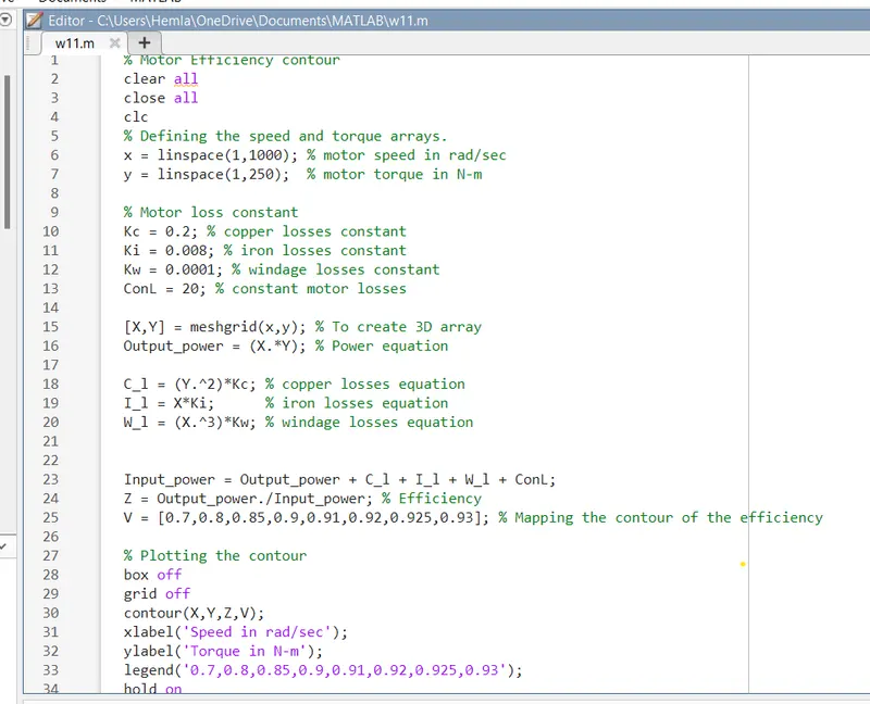
Based on these 3 losses the MATLAB program to plot the efficiency contour
is given below
% Motor efficiency contour.
clear all
close all
clc
% Defining the speed and torque arrays.
x = linspace(1,1000); % Motor speed in rad/sec
y = linspace(1, 250); % Motor torque in N_m
% Motor loss constants
Kc = 0.2; % Copper losses constants
Ki = 0.008; % Iron losses constants
Kw = 0.0001; % Windage losses constants
ConL = 20; % Constant motor losses
[X,Y] = meshgrid(x,y); % To create a 3D array
Output_power = (X.*Y); % Power equation
C_l = (Y.^2)*Kc; % copper losses equation
I_l = X*Ki; % Iron losses equation
W_l = (X.^3)*Kw; % windage losses equation
Input_power = Output_power + C _l + I_l + W_l + ConL;
Z = Output_power. / Input_power; % Efficiency
V = [0.7,0.8,0.85,0.9,0.91,0.92,0.925,0.93]; % Mapping the contour of the efficiency
% Plotting the contour
box off
grid off
contour(X,Y,Z,V);
xlabel('Speed in rad/sec');
ylabel('Torque in N-m');
legend('0.7,0.8,0.85,0.9,0.91,0.92,0.925,0.93');
hold on
Explaination:
1] First the clear all, close all and clc commands are written to clear all variables
in workspace, to clear all plots and to clear the workspace respectively.
2] The speed and torque are defined as 2-Dimensional linearly spaced arrays using
the linspace command.
3] The constants of the motor losses are defined.
4] The 2-D arrays of the speed and torque are then defined as 3-D arrays using
meshgrid command.
5] The output power equation is defined as the product of speed and torque.
6] The equation of motor losses based on the speed and torque are defined.
7] The input power is defined as the sum of output power plus motor losses.
8] The efficiency is then defined as the ratio of output power to input power.
9] In order to map the contour for different efficiency ranges an array is
defined which consists of the efficiencie from 0.7 to 0.93.
10] The graph is plotted using the contour command to plot the speed, torque
and efficiency.
Output :
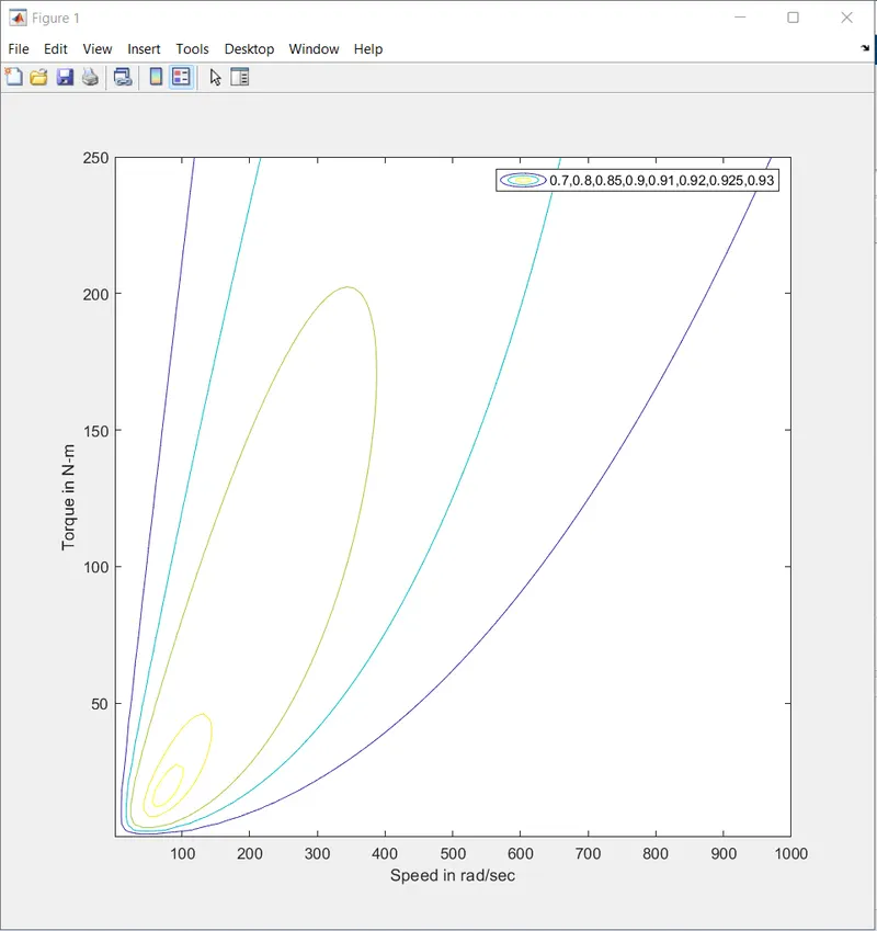
From the output, it can be observed that the speed and torque varies as the
efficiency increases. This is due to the motor losses that occur. The dark blue
line represent the contour 70% efficiency and the bright yellow line represents
the contour 93% efficiency.
For eg. at 70% efficiency, the torque reaches its peak value of 250 N-m when
the vehicle is very low speed but the torque decreases significantly as the speed
increases for the same efficiency. And at a motor efficiency of 93% the speed and
torque required is much less compared to an efficiency of 70%.
Greater the motor efficiency, lower speed-torque combination is required to
overcome the motor losses.
https://drive.google.com/file/d/1WA1wU2cKuu4nmzsRKgTjkwJYBmaVssWn/view?usp=sharing