Project 2 Thermal modeling of battery pack
Aim: Thermal Modelling of Battery Pack
Objective:
For a 10 cell series lithium ion battery model, simulate the thermal effects and compare life cycle
performance at various temperatures, charge & discharge rates using MATLAB.
Introduction:
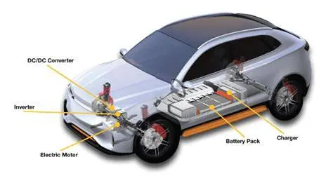
Lithium Ion Battery Pack:-
The lithium ion battery pack is a modern rechargeable battery pack that connects two or more
lithium- ion batteries in series or parallel configurations to increase ratings like voltage, capacity,
current, and energy.
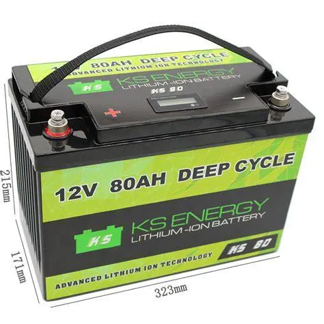
Lithium-ion batteries are one of the most popular types of rechargeable batteries for consumer
electronics, electric vehicles, aerospace, medical, and other applications. The 18650 battery pack is
steadily gaining market share over traditional lead-acid batteries.
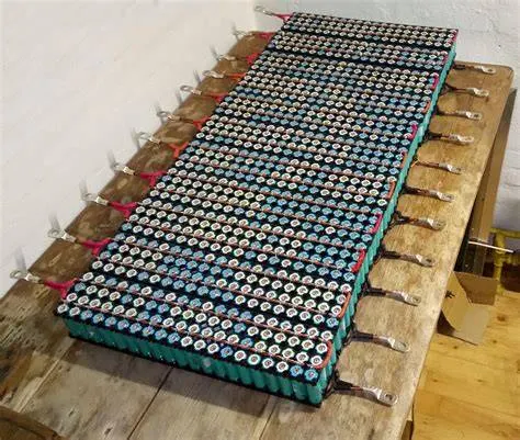
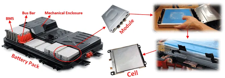
The modern day lithium ion battery pack is safe, reliable, and offers high levels of performance. A
lithium ion battery pack is normally powered by a cylindrical battery of the size format 18650 or
larger like 21700 or 26650. Or, they can be powered by lipo batteries (pouch) or prismatic batteries.
Most packs include protective circuitry like a PCM or a more advanced BMS.
Different Types of Lithium-ion Batteries, Working, Applications:
The lithium-Ion battery is a rechargeable battery that is composed of lithium elements in the
positive electrode and graphite in the negative electrode. The main working of the lithium-ion
battery is the lithium ions move from the positive electrode to the negative electrode during
discharging of the battery and while charging the lithium ions will move back from negative
electrode to positive electrode.
The lithium ion battery was invented in the year 1958 by Japanese chemist Akira Yoshino as a
prototype model later the battery was commercially developed by the Sony company in the year
1991. This battery has an advantage such as high energy density, no memory effect on cells
and lithium-ion has low self-discharge property compared to the other electrical batteries. The
lithium- ion battery works on the main principle of electrochemical effect.
Construction:
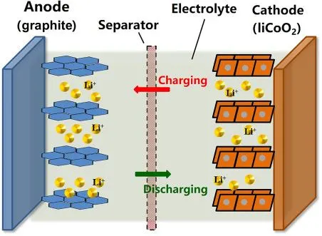
The lithium-ion battery mainly consists of the positive electrode which is popularly known as Anode
and a negative electrode which is popularly known as cathode and separator, electrolyte and two
current terminals named as positive and negative collectors. The separator is used to separate the
electrodes and electrolyte is a solution used for the electrochemistry process. The two current
collectors are the outlets of the battery where the consumer can connect the respective load.
Working:
The working of the lithium-ion battery is mainly divided into two processes such as Charging and
Discharging. During Charging the lithium ions will move from the positive electrode to the negative
electrode and the current will be delivered at the outlets of the battery i.e., collectors. During
Discharging the lithium ions will move from the negative graphite electrode to the positive lithium
electrode where no current will be passed through the current outlets.
The chemical reaction of the lithium ion battery is given below:
{LiC6 + CoO2 <=> C6 + LiCoO2}
The above chemical equation from right to left will give you the charging condition and from left to
right it is given as the discharging condition. This is the main work involved in the lithium-ion
batteries.
There are mainly six types of lithium-ion batteries available in the global market:
1. Lithium Cobalt Oxide Battery
Lithium cobalt oxide batteries mainly consist of three parts anode, cathode and electrolyte. The
cathode of lithium cobalt oxide battery is made up of lithium and cobalt elements and the anode is
made up of graphite. The electrolyte of the battery is made up of lithium salts. The main work
involved in the lithium cobalt oxide battery is the same as the lithium-ion battery. During
discharging state the lithium oxide elements made up of cobalt will flow from anode to cathode.
During charging state the lithium oxide elements made up of cobalt will flow from the cathode to the
anode. The electrolyte is a salt bridge that is used to make the electrolysis process a smoother way
without any changes in the ions exchange between electrodes. This battery is mainly used in
portable electronic gadgets such as cell phones, laptops and digital cameras as its energy density is
comparatively less and self-discharge property is less.
2. Lithium Manganese Dioxide Battery
Lithium Manganese dioxide batteries mainly consist of three parts anode, cathode and electrolyte.
The cathode of lithium manganese dioxide battery is made up of lithium dioxide elements made up
of Manganese and anode is made up of graphite. The electrolyte of the battery is made up of lithium
salts. During discharging state the lithium oxide elements made up of Manganese will be flow from
anode to cathode. During charging state the lithium dioxide elements made up of Manganese will
flow from the cathode to the anode.
The electrolyte is a salt bridge that is used to make the electrolysis process the smoother way
without any changes in the ions exchange between electrodes. This battery is mainly used in the
microcontrollers and microcomputers power supply and it is mainly used for automatic cameras.
3. Lithium Iron Phosphate Battery
The Lithium Iron Phosphate battery works on the main principle of electrochemical effect. The
cathode is made up of a combination of lithium, iron and phosphate but the anode is made up of
graphite. The major application of the LFP battery are it is used in passenger cars, logistic vehicles
and low speed electric vehicles.
4. Lithium Nickel Cobalt Aluminium Oxide Battery
Lithium Nickel Cobalt aluminium oxide battery consists of a cathode made up of Nickel, cobalt and
aluminium (NCL) and the negative electrode is made up of carbon graphite. This is one of the
trending batteries in the world as it is mostly used in electrical automobiles. This is also used in
portable electronic devices.
5. Lithium Nickel Manganese Cobalt Oxide Battery
Lithium Nickel Manganese Cobalt oxide battery consists of a cathode made up of Nickel, Manganese
and cobalt (NMC) and the negative electrode is made up of carbon graphite. This is one of the
trending batteries in the world as it is mostly used in medium speed electrical automobiles.
6. Lithium Titanate Battery
The lithium titanate battery is the fastest rechargeable battery. The cathode is made up of lithium
oxide elements made up of titan element and the anode element is made up of carbon graphite.
This is the fastest charging battery and slow rate while discharging, this property made it used in
many applications. This batteries can be used for small unit operations and they are also used for
electrical bikes as large units. The market price for lithium titanate oxide is Rs 2400/- per unit. This
is mostly used in small voltage applications.
Series configuration
The series configuration is used where the voltage of a single cell is not sufficient. The series
configuration is achieved by connecting the positive of a cell to the negative of another cell, as
shown in the image below. The four lithium-ion cells of 3.6 V connected in series will give you 14.4 V,
and this configuration is called 4S because four cells are connected in series.
The number of cells can be varied according to the voltage of a single cell. A Lead-acid battery has a
nominal voltage of 2 V, so it requires six cells connected in series to achieve 12 V. The six alkaline
batteries of voltage 1.5 V per cell connected in series will give you 9 V.
If the device needs an odd voltage, for example, 10 volts, then three Li-ion batteries can be
connected in series. But when the device needs 8.5 volts from Li-ion, we need to know the
specification of our device. If it can handle 10 V, then it can be connected directly; otherwise, a
buck or boost is used to achieve 8.5 V.
If one cell in series is faulty, cell matching is a challenge in an aging pack at the time of cell
replacement. The new cell has a higher capacity than the others, which causes imbalance. That’s
why battery packs are commonly replaced in units.
BMS (Battery Management Systems) or its controller can determine the faulty battery by measuring
the voltage at every point of the battery as shown below in the image. The one cell is faulty, which is
giving 2.8 V instead of 3.6 V. Due to this, the battery voltage collapses, and the device will shut off
sooner with a low-battery message. We can repair our battery pack by replacing this cell.
Thermal issues associated with electric vehicle battery packs can significantly affect performance
and life cycle. Fundamental heat transfer principles and performance characteristics of commercial
lithium-ion battery are used to predict the temperature distributions in a typical battery pack under
a range of discharge conditions. Various cooling strategies are implemented to examine the
relationship between battery thermal behavior and design parameters. By studying the effect of
cooling conditions and pack configuration on battery temperature, information is obtained as to how
to maintain operating temperature by designing proper battery configuration and choosing proper
cooling systems. It was found that a cooling strategy based on distributed forced convection is an
efficient, cost-effective method which can provide uniform temperature and voltage distributions
within the battery pack at various discharge rates.
Simulink Model of Lithium ion battery pack with Fault :
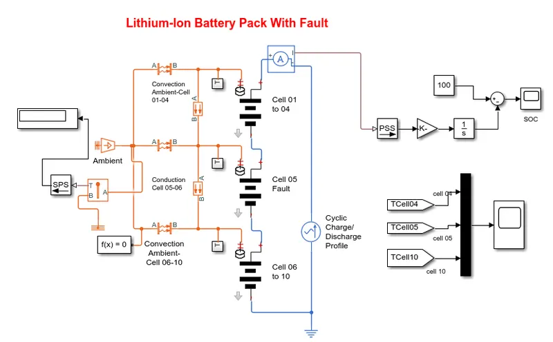
For the 10-cell series lithium-ion battery here I have used Matlab and Simulink for findings thermal
effect and life cycle performances related to temperature, charge, and discharge and also conduction
and convection blocks are used to show how the heat transfer takes place in battery packs.
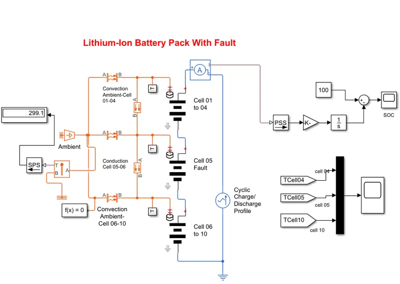
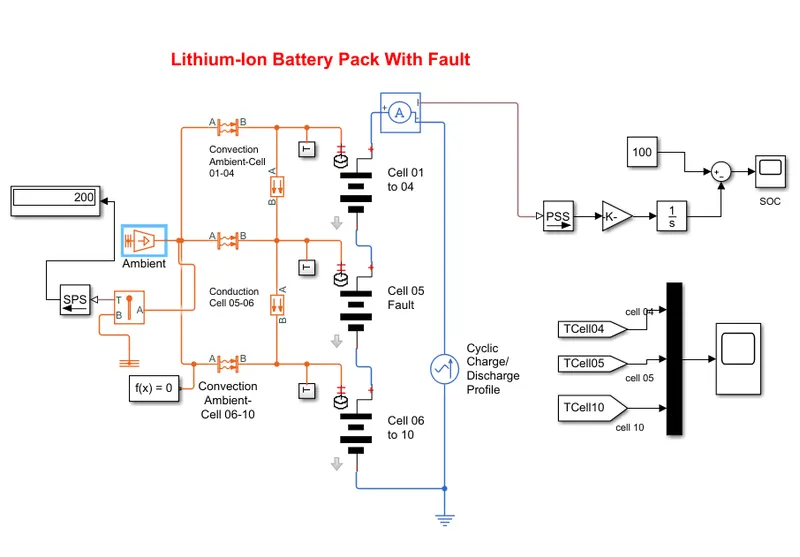
Lithium-ion battery pack with fault is to simulate a battery pack consists of multiple cells connected
in series efficiently.It also shows how a fault can be introduced into one of the cells to the impact on
battery performance and cell temperatures, for efficiency the identical series-connected cells are not
just simply model by connecting cell models in series. Instead single cell is used, and the terminal
voltage is scaled up by the number of cells. The fault is represented by changing the parameters for
the cell 5 subsystem, reducing both the capacity and open-circuit voltage, and increasing the
resistance values.
Connections:
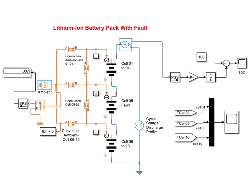
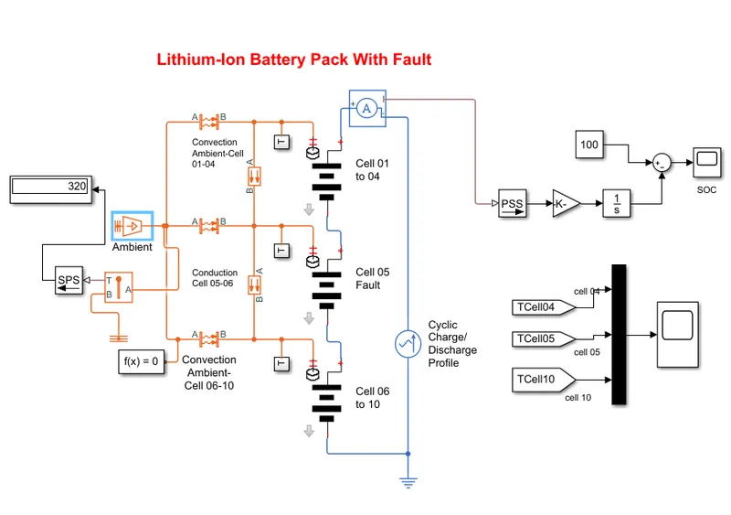
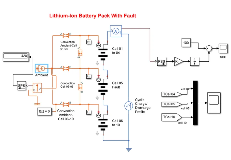
1. 10 lithium-ion battery cells are connected in with the combination of three packs the 1st pack
consistent 4 cells in series 2nd pack consist of 1 cell which set to design as fault for study purpose to
observe temperature changes within battery pack and the 3rd pack contain 5 cells in series.
2. The heat transfer is observed between the packs by conduction and convection block which are
modes of heat transfer.
3. T subsystem is attached in between every pack to plot the temperature graph of the cell of that
particular battery pack.
4. Also external ambient temperature source is attached and also thermal sensor is attached to the
same to indicate the value in the display.
5. This battery pack is connected to AC current source to observe the cyclic charge and discharge
rate graph.
6. Also we have added a current sensor in between the battery pack and AC current source to
calculate the SOC of the battery.
7. The cell temperature and soc graphs are plotted in scope which indicating the temperature of cell
no 4, cell no 5, and cell no 10.
Cell 01 to 04 Subsystem:
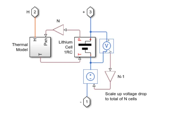
The cell subsystem basically consists of a thermal model and lithium cell 1RC block which calculate
the temperature and thermal effect for cells and overall calculate for the battery pack.
The block which are inside the cell subsystems are PS gain block which multiplies the input physical
signals by a constant i.e y=u.*gain .another block are voltage sensor and current-voltage source.
The voltage sensor block represents an ideal voltage sensor, this is a device that converts voltage
measured between any electric connection into a physical signal proportional to the voltage.
The current-voltage source represents an ideal voltage source that is powerful enough to maintain
the specified voltage at its output regardless of the current passing through it. The output voltage is
V=Vs, where Vs is the numeric value represents at the physical signal port.
A] Thermal model:
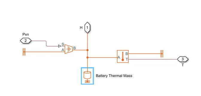
The blocks present inside the systems are,
1. Thermal Reference
Reference connection for thermal ports
Library
Thermal Elements
The Thermal Reference block represents a thermal reference point, that is, a point with an absolute
zero temperature, concerning which all the temperatures in the system are determined.
2. Controlled Heat Flow Rate Source
The Controlled Heat Flow Rate Source block represents an ideal source of thermal energy that is
powerful enough to maintain specified heat flow at its outlet regardless of the temperature
difference across the source.
Connections A and B are thermal conserving ports corresponding to the source inlet and outlet,
respectively. Port S is a physical signal port, through which the control signal that drives the source
is applied. We can use the entire variety of Simulink® signal sources to generate the desired heat
flow variation profile. The heat flow through the source is directly proportional to the signal at the
control port S.
The block positive direction is from port A to port B. This means that a positive signal at port S
generates heat flow in the direction from A to B.
3. Thermal Mass
The Thermal Mass block represents a thermal mass, which reflects the ability of a material or a
combination of materials to store internal energy. The property is characterized by the mass of
the material and its specific heat. The thermal mass is described with the following equation:
Q=c·m*dT/dt
4. Temperature Sensor
The Temperature Sensor block represents an ideal temperature sensor, a device that determines the
temperature differential measured between two points without drawing any heat.
Connections A and B are thermal conserving ports that connect to the two points where the
temperature is being monitored. Port T is a physical signal port that outputs the temperature
differential value.
The block positive direction is from port A to port B. The measured temperature is determined as
T = TA – TB.
B] Lithium Cell 1RC subsystem:
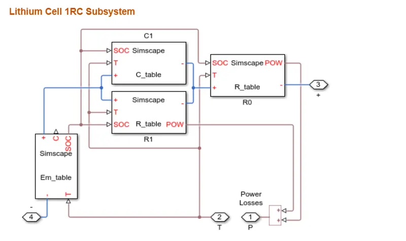
This block especially consists of the capacitor (C)value table which depends upon an external
physical signal input SOC and T.it is assumed that the capacitor value is varying with the time and
hence the equation i=C*DV/dt holds.
Resistance value (R) table depend on external physical signal inputs SOC and T.
Voltage value (EM) implements the cell's main branch voltage source and determines values for
capacity(C) and state of charge (SOC). The defining the equations depends upon cell temperature T.
C] Thermal Behaviour and Fault Setup:
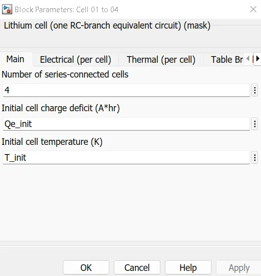
Lithium-ion one cell one RC-Branch equivalent circuit detail for 10 cells
For cell 01 to 04
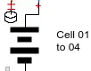
Number of connected in series are:-4
Initial temperature:-299.1 k
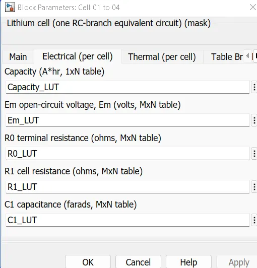
For cell 5 cells
Fault setup in this cell,
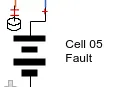
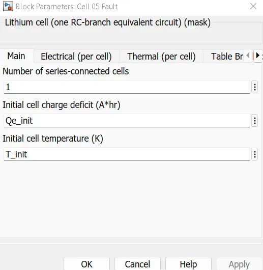

Number of connected in series are=1
Initial temperature=299.1 k
Capacity(A*hr)=Capcity_LUT*0.95
EM-open-circuit voltage (volts)=Em_LUT*0.9
RO terminal resistance (ohms)=RO_LUT*5
R1 cell resistance (ohms)=R1_LUT*5
C1 capacitance(farads)=C1_LUT*0.95
For cell 06 to 10
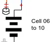
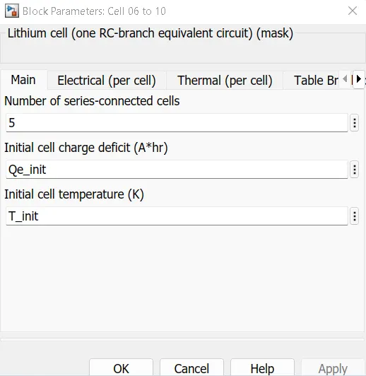
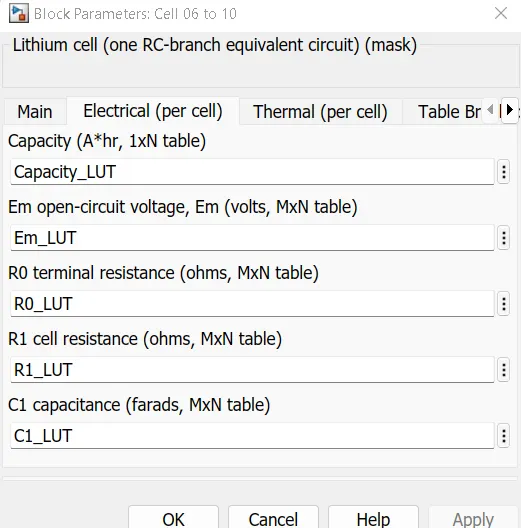
Number of connected in series are:-5
Initial temperature:-299.1 k
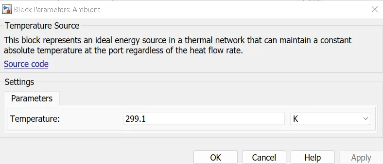
Temperature Source
The Temperature Source block represents an ideal source of thermal energy that is powerful enough
to maintain a specified temperature at its outlet regardless of the heat flow consumed by the
system. The source generates constant absolute temperature, defined by the Temperature
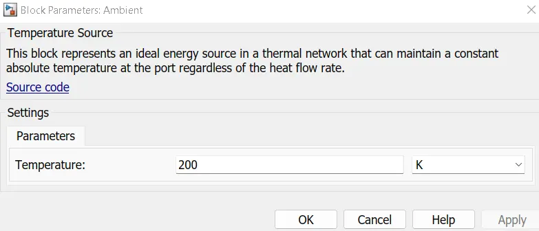
parameter value. Here I have used ambient block and set the temperature for 299.1k or 25.95 C.
D] Thermal Elements:
Conductive Heat Transfer
The Conductive Heat Transfer block represents a heat transfer by conduction between two layers of
the same material. The transfer is governed by the Fourier law and is described with the following
equation:
Q=k·AD(TA−TB)
where,
Q = Heat flow
K = Material thermal conductivity
A = Area normal to the heat flow direction
D = Distance between layers (thickness of material)
TA, TB = Temperatures of the layers
Connections A and B are thermal conserving ports associated with material layers. The block
positive direction is from port A to port B. This means that the heat flow is positive if it flows from A
to B.
The is done from the 2 sets of blocks .one is for cell 04 to 05 and another is used for 05 to 06.
Convective Heat Transfer
The Convective Heat Transfer block represents a heat transfer by convection between two bodies
using fluid motion. The transfer is governed by the Newton law of cooling and is described with the
following equation:
Q=k·A·(TA−TB)
Where,
Q = Heat flow
K = Convection heat transfer coefficient
A = Surface area
TA,TB = Temperature of 2 bodies
Connections A and B are thermal conserving ports associated with the points between which the heat
transfer by convection takes place. The block positive direction is from port A to port B. This means
that the heat flow is positive if it flows from A to B.
Here, I have used 3 blocks for convection
For cell 01-04
For cell 05
For cell 06-10
Temperature Sensor
The Temperature Sensor block represents an ideal temperature sensor, a device that determines the
temperature differential measured between two points without drawing any heat.
Connections A and B are thermal conserving ports that connect to the two points where the
temperature is being monitored. Port T is a physical signal port that outputs the temperature
differential value.
The block positive direction is from port A to port B. The measured temperature is determined as T
= TA – TB.
D] Electrical Elements
Output of one cell is connected with the SOC calculation whereas the output is connected to with AC
source for the cyclic charge/discharge profile.
1. AC Current Source
The AC Current Source block represents an ideal current source that maintains the sinusoidal current
through it, independent of the voltage across its terminals.
The output current is defined by the following equation:
I=I0⋅sin(2π⋅f⋅t+φ)
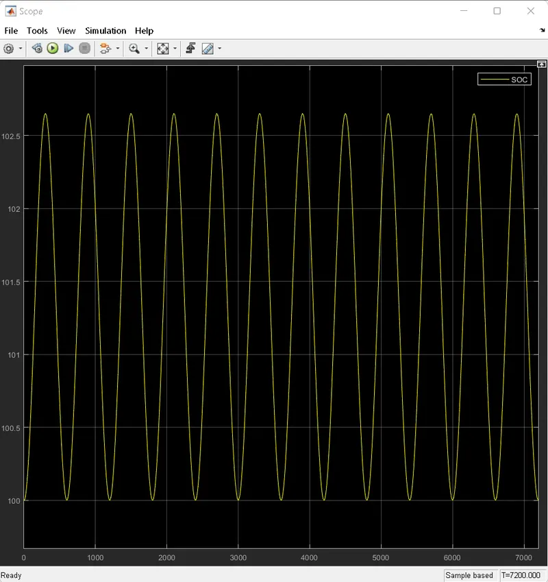
The peak amplitude is set to 50 A for a cyclic charge and discharge. A basic parameter of AC source
is as,
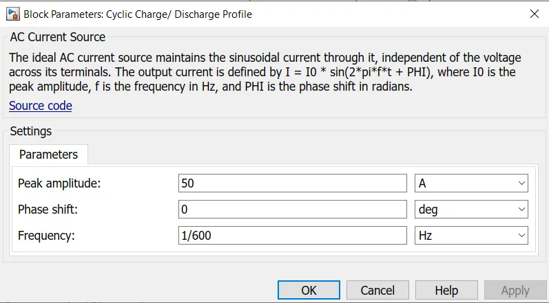
The ideal AC source maintains the sinusoidal current through it, independent of the voltage across its
terminals. The output current is defined by I=I0*sin(2*pi*f*t+PHI) I0 is the peak amplitude,f is the
frequency in Hz, and PHI is the phase shift in radians.
2. Current Sensor
The Current Sensor block represents an ideal current sensor, a device that
converts current measured in any electrical branch into a physical signal proportional to the current.
Connections + and – are electrical conserving ports through which the sensor is inserted into the
circuit. The connection I is a physical signal port that outputs the measurement result.
3. Electrical reference
The Electrical Reference block represents an electrical ground. Electrical conserving ports of all the
blocks that are directly connected to the ground must be connected to an Electrical Reference block.
A model with electrical elements must contain at least one Electrical Reference block.
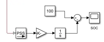
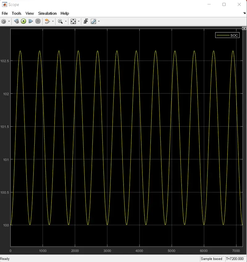
4. SOC Calculation
The Coulomb counting method measures the discharging current of a battery and integrates the
discharging current over time in order to estimate SOC.
This system takes current as input and gives the battery SOC % as output. A current sensor
block is used and connected for soc estimation.
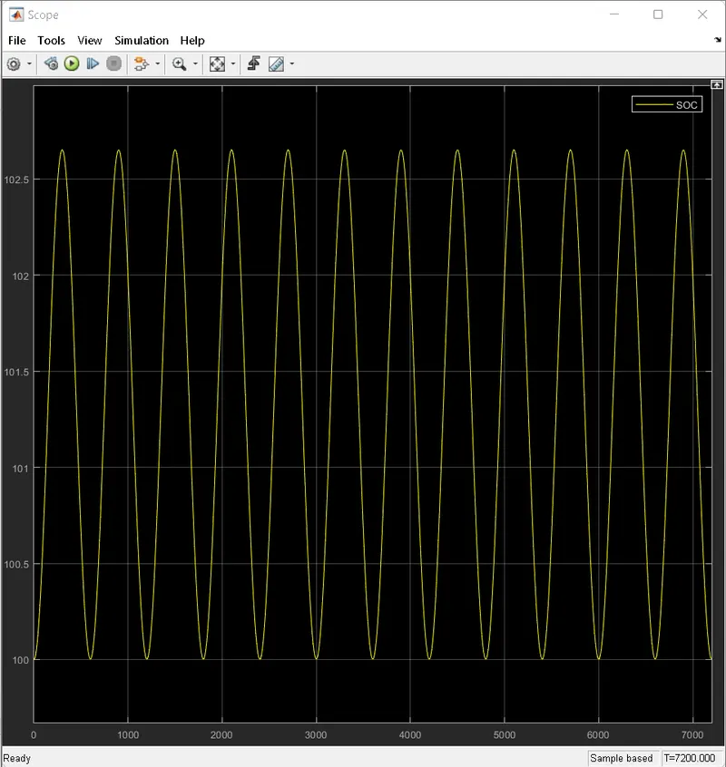
This ckt estimates the battery SOC % using coulomb counting method. It takes current as the input
and gives SOC% as output. Initial SOC of the battery is assumed to be 100% (1)
example shows how to simulate a battery pack consisting of multiple series-connected cells in an
efficient manner. It also shows how a fault can be introduced into one of the cells to see the impact
on battery performance and cell temperatures.
Case 1:- For Temperature = 299.1 K
Simulink model is shown below;
Block parameter:
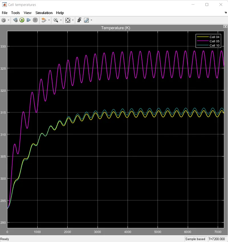
Result of all the cell temperature and SOC:
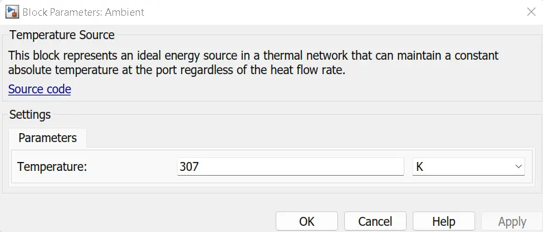
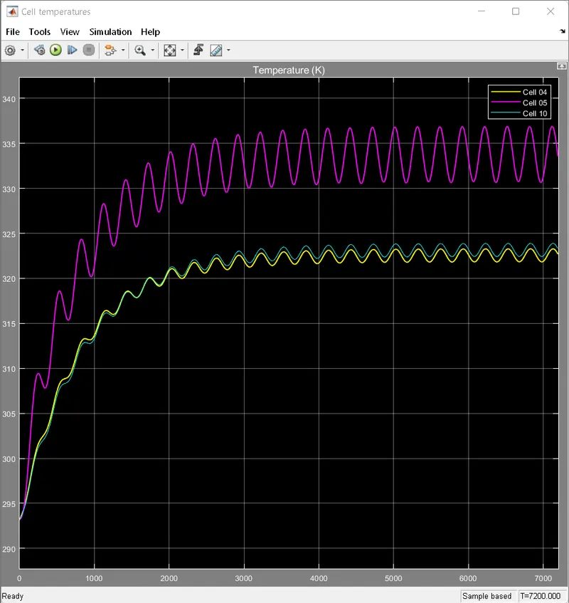
Case 2:- For Temperature = 307 K
Simulink model is shown below;
Block parameter:
Result of all the cell temperature and SOC:
Case 3:- For Temperature = 320 K
Simulink model is shown below;
Block parameter:
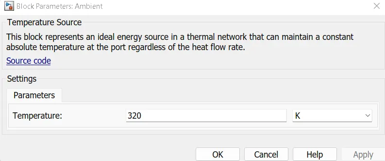
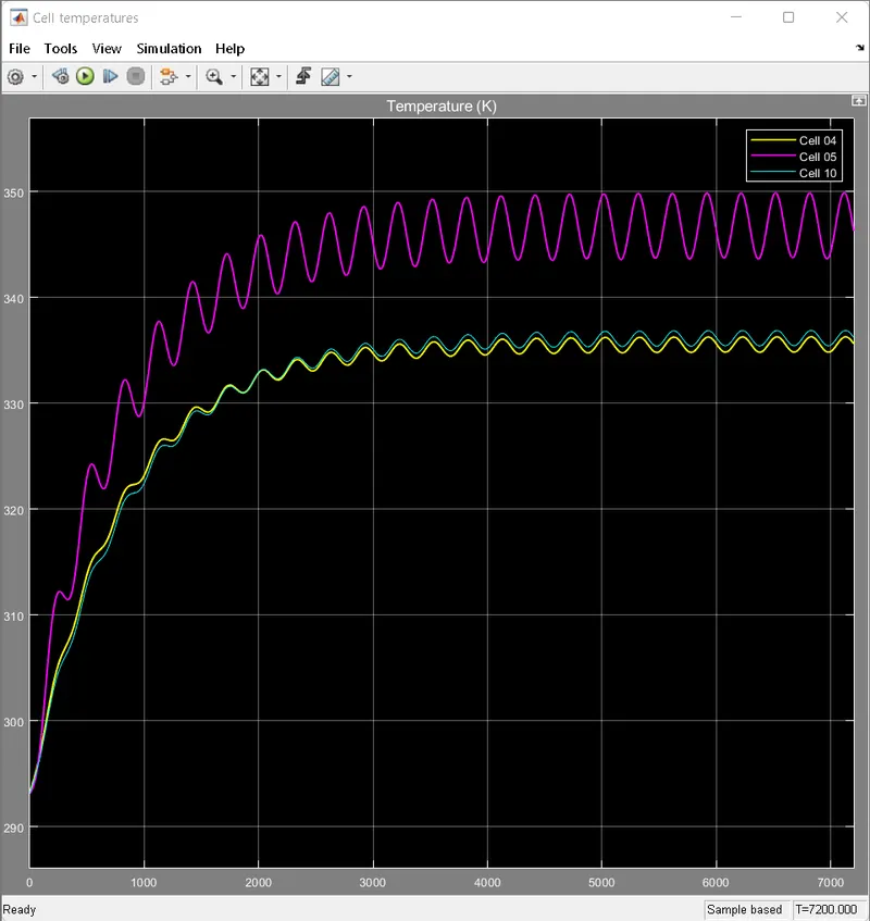
Result of all the cell temperature and SOC:
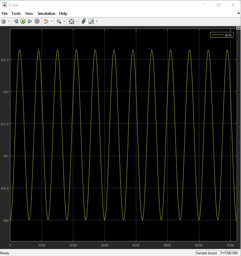
Case 4:- For Temperature = 345 K
Simulink model is shown below;
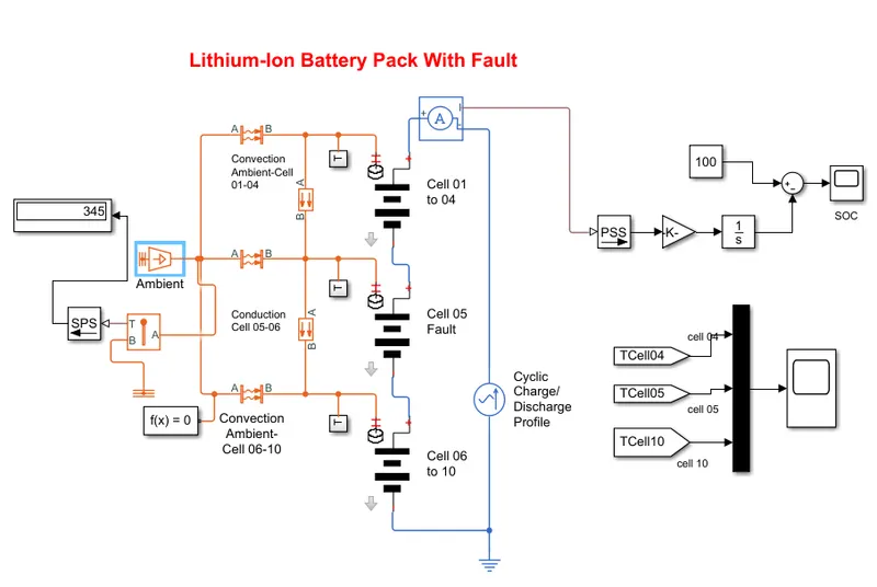
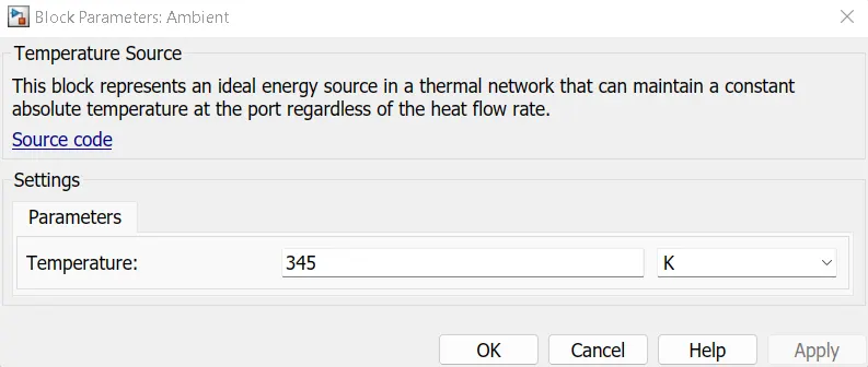
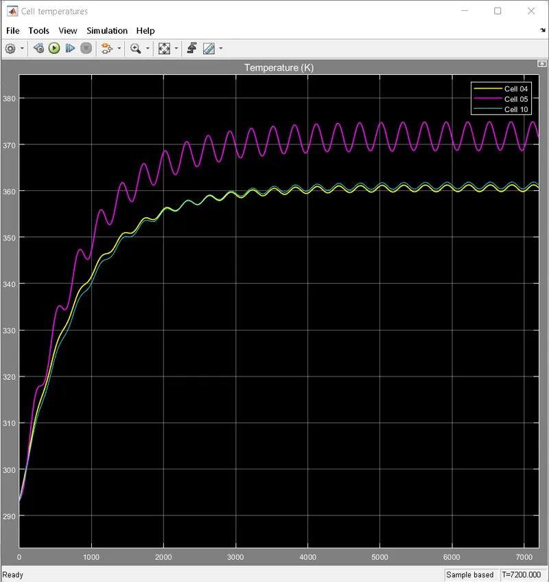
Result of all the cell temperature and SOC:
Case 5:- For Temperature = 200 K
Simulink model is shown below;
Block parameter:
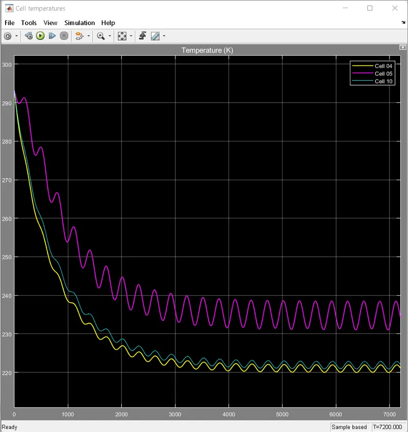
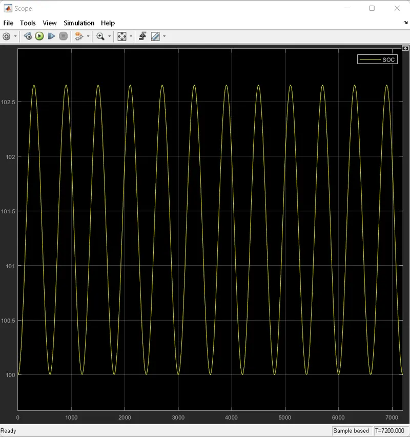
Result of all the cell temperature and SOC:
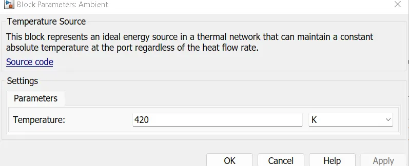
Case 6:- For Temperature = 420 K
Simulink model is shown below;
Block parameter:
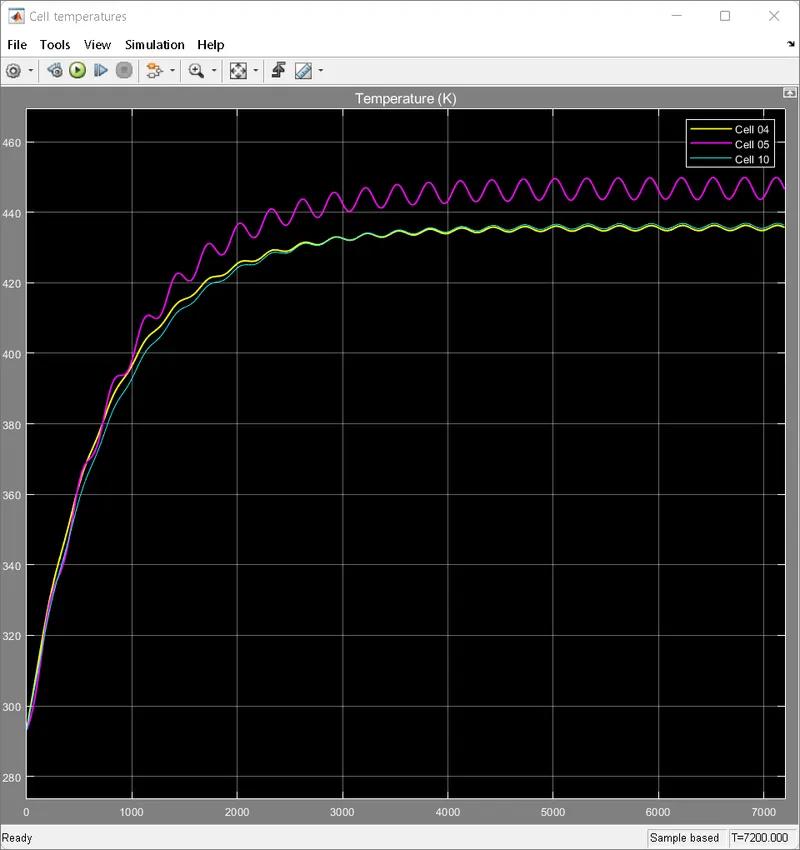
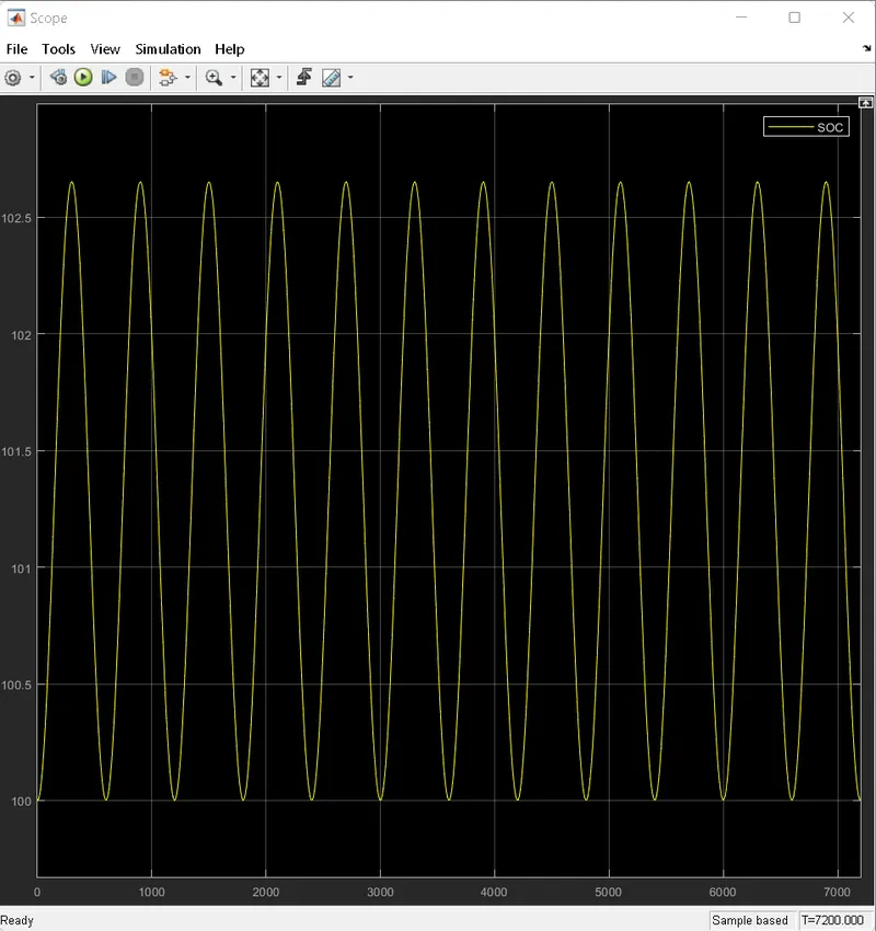
Result of all the cell temperature and SOC:
Comments:
For a 10 cell series lithium ion battery model we simulate the thermal effects and compare life
cycle performance at various temperatures, charge & discharge rates using MATLAB. results are as
follows;
1-4 cells are normal cell 5 th cell is faulty 6-10 cell is normal cell as we are simulating thermal effect
on we give Cyclic Charge/ Discharge Profile to circuit the waveform we can see above results all
conditions it is same but when ckt is run on this drive cycle profile as 5th cell was faulty it will show
temperature rise high than any other cell and the life cycle of cell get reduced and cell even can get
damage.
In case no.1, As we give temp of 299.1 k, the 1-4 and 6-10 cell temp is near to 315 k but
5th faulty cell temp goes to 325k and the drive cycle is shown which is Cyclic Charge/ Discharge
drive cycle.
In Case no.2 ,we give temp 320 k, 1-4 and 6-10 cell temp is near to 323 k but 5th faulty cell temp
goes to 334 k and the drive cycle is shown which is Cyclic Charge/ Discharge drive cycle.
In Case no.3 we give temp 320 k, 1-4 and 6-10 cell temp is near to 336k but 5th faulty cell temp goes to
346 k and the drive cycle is shown which is Cyclic Charge/ Discharge drive cycle.
In Case no.4 we give temp 345 k, 1-4 and 6-10 cell temp is near to 361 k but 5th faulty cell temp goes to
372 k and the drive cycle is shown which is Cyclic Charge/ Discharge drive cycle.
In Case no.5 we give temp 200 k, 1-4 and 6-10 cell temp is near to 222 k but 5th faulty cell tempreaches to
235 k and the drive cycle is shown which is Cyclic Charge/ Discharge drive cycle.
In Case no.6 we give temp 420 k, 1-4 and 6-10 cell temp is near to 428 k but 5th faulty cell temp goes to
444 k and the drive cycle is shown which is Cyclic Charge/ Discharge drive cycle.
This faulty cell i.e cell no. 5 reduces the overall efficiency of the battery pack.
Tabular representation of all obtained results from above the all simulations:
Case No. Temperature given (K) Cell no.(1-4)&(1-6)Temp. [k] Cell no.5 Temp.(k)
(Faulty cell)
1 299.1 315 325
2 307 323 334
3 320 336 346
4 345 361 372
5 200 222 235
6 420 428 444
Conclusion:
From the above all simulations, it is clear that the cell no. 5 requires efficient cooling techniques
to keep the temperature within limits. Otherwise, thermal runaway occurs which results in damage
of the entire battery pack. Also, cell no. 5 being the weak cells, the overall performance of the
battery is affected. Full capacity of the battery cannot be taken out. To avoid the adverse impacts of
high-temperature conditions a Thermal Management System is required to monitor the temperature
and to provide effective cooling. Hence, it is understood from these simulations, the effect of
temperature on driving as well as charging for various climatic conditions.
Simulink file:
https://drive.google.com/file/d/1XtY6HqTJnkUr7BTiNGqR-zxkF6Jq0oUj/view?usp=sharing
Kindly open attached simulink file with MATLAB/Simulink.