Project 1 Mechanical design of battery pack
Aim: Design a mechanical battery pack.
Objective:
Battery pack capacity: 18 kWh
Cell: ANR26650M1-B
Prepare a detailed battery pack drawing along with its enclosure. State your assumptions.
Introduction:
A123 Systems ANR26650M1-B 2500mAh 3.3V LiFePO4 nanophosphate rechargeable
Lithium ion battery
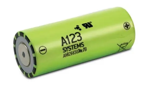
Nanophosphate® ANR26650M1-B:
A123 Systems ANR26650M1-B 2500mAh 3.3V LiFePO4 nanophosphate rechargeable Lithium ion
battery is the next generation of A123 Systems pioneering 26650 cylindrical cell, now with greater
power and energy density and lower impedance. This versatile lithium ion cell is suitable for a wide
variety of applications and system designs. Proven performance in the toughest conditions, combining
durability, reliability, and safety, the ANR26650 cell offers an excellent combination of price-
performance.
Cylindrical Cell Primary Applications:
1. Portable high power devices
2. Stationary battery backup systems
3. Grid stabilisation energy storage systems
4. Commercial truck and bus hybrid electric vehicles (HEVs)
Lithium Ion Cell Benefits:
1. Power: Over 2,600 W/kg and 5,800 W/L
2. Safety: Excellent abuse tolerance and environmentally friendly
3. Life: Excellent calendar life, 10X cycle life vs. conventional lithium ion
Discharge Curve
Battery Specification:
1. Model: ANR26650M1-B
2. Positive terminal style: Flat-top
3. Protected (PCB): No
4. Manufacturer: A123 Systems
5. Country of Origin: USA and China
6. Chemistry: LFP (LiFePO4)
7. Max. continuous discharge current: 70A
8. Maximum pulse discharge: 120A
9. HPPC 10 sec Discharge pulse power: 200W
10. Rated capacity (minimum): 2500 mAh
11. Nominal capacity: 2500 mAh
12. Nominal voltage: 3.3 V
13. Discharge end voltage: 2 V
14. Charging voltage: 3.6 +/- 0.03 V
15. Standard charging current: 2.5A (1C)
16. Fast charging current: 10A (10C)
17. Operating temp: -40 degrees C to +60 degrees C
18. Dimensions: 65mm (L) x 26mm (D)
Cell Calculations:
1] Cell volume = π x r^2 x h
= 3.14 x 0.013 x 0.013 x 0.065
Cell volume = 0.00265333m^3
2] Cell energy = Nominal voltage * Nominal cell capacity
= 3.3 x 2.5
Cell energy = 8.25 Wh
3] Cell energy density = cell energy / cell volume
= 8.25 / 0.0026533
Cell energy density = 3.11 KW.h/m3
Battery Pack Assumptions:
1. All the cells are ANR26650M1-B type.
2. There are 46 cells in series and 48 cells in paralllel of the battery pack.
Battery Pack Calculations:
1] Total number of cells = 46 x 48
Total number of cells = 2208 Cells
2] Voltage = Nominal voltage of a cell x number of cells in series
= 3.3 x 4.6
Voltage = 151.8 V
3] Capacity = Nominal cell capacity x number of cells in parallel
= 2.5 x 48
Capacity = 120 Ah
4] Energy = Voltage x Capacity
= 151.8 x 120
Energy = 18216 = 18.216 KWh
5] Volume = Cell volume x Total number of cells
= 0.0026533 x 2208
Volume = 5.86m^3
6] Energy density = Battery pack energy / Volume
= 18216 / 5.86
Energy density = 3.11 kWh/m^3
7] Weight = Total number of cells x Cell weight
= 2208 x 0.076
Weight = 167.81 Kg
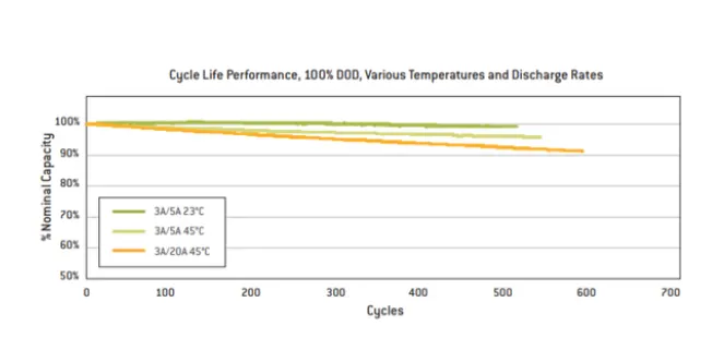
ANR26650M1-B Specifications
Discharging
Max Continuous Discharage: 50 A
Max Pulse Discharge Current >50% SOC (10s): 120 A
Minimum Voltage: 2 Volts
Temperature: -30ºC to 55ºC
Charging
Recommended Standard Charge: 2.5 Amp
Max Charge Rate: 10 Amps
Max Pulse Charge Current <50% SOC (10s): 25A
Float Voltage: 3.45 Volts
Recommended charge V & Cut-off Current: 3.6 Volts, taper to 125mA
Temperature : (reduce charging current to 250mA when under 0ºC): 0ºC to 55ºC
Mechanical
Diameter: Ø25.96 +/- 0.5 mm (1.0")
Length: 65.15 +/- 0.5 mm (2.6")
Mass: 76 g
Battery Pack Construction:
1. Voltages and Capacity:
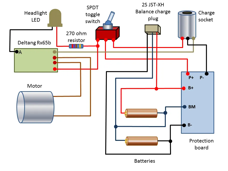
Cells can be combined together either in series or in parallel to achieve higher operating voltages
and capacities, respectively.
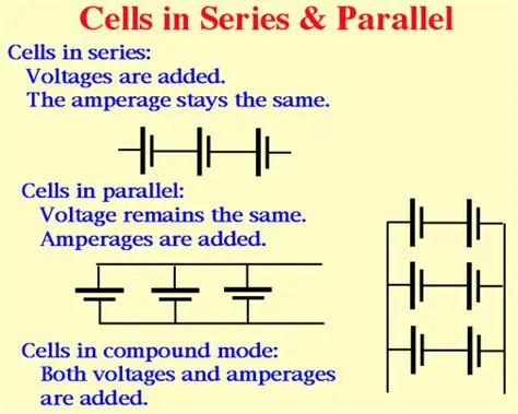
2. Series Strings:
Cells combined in series strings can achieve higher operating voltages by connecting the positive
terminal of one cell to the negative terminal of the next cell. Connect strings of series cells using
their current collection tabs in a manner similar to that illustrated in Figure,
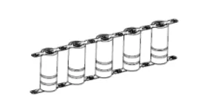
3. Parallel strings:
Cells combined in parallel strings can achieve higher operating capacities by connecting like-polarity
terminals of adjacent cells to each other. Connect strings of parallel cells using their current
collection tabs in a manner similar to that illustrated in Figure,
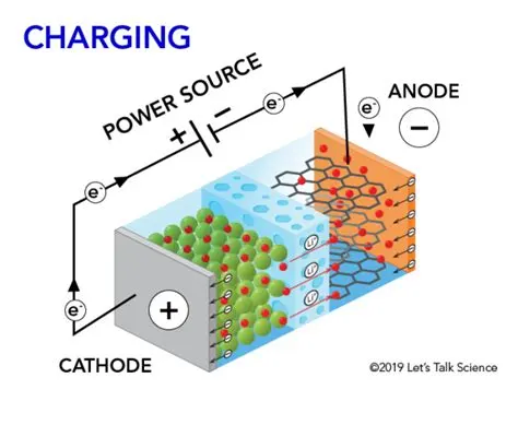
4. Charging Cells:
Charging or Recharging Cells or Strings When charging or recharging Nanophosphate cells, the
charger should apply a constant current (CC) charge followed by a constant voltage (CV) charge.
To achieve maximum life, reliability, and safety, A123 Systems recommends using cell balancing
circuitry during cell charging to prevent an increasing spread between highest and lowest battery
voltages. Refer to Cell Balancing on page 41 for more information. Stop the charging process when
either:
1. The string voltage across the pack has exceeded the recommended maximum charging voltage
for the string, or
2. Any one cell in the series string, has exceeded its maximum recommended charge voltage, or
3. The temperature measured in the pack has gone outside the recommended range for charing.
Determine the charge current for a string of cells by multiplying the number of parallel cells in the
string by the recommended charge current for a single cell. Note that this calculation does not take
into account limitations imposed by any protection electronics or any other features of the battery
pack assembly.
(Number of cells in parallel) x (Recommended Charge Current, Cell) = Charge Current, String
determine the end of charge voltage for a string of cells by multiplying the number of series
elements in the string by the recommended charge voltage of a single cell.
5. Discharging Cells:
Recommended Discharge Method for Strings Determine the maximum continuous discharge current
for a string of cells by multiplying the number of parallel cells in the string by the maximum
continuous discharge current for a single cell. Note that this calculation does not take into account
limitations imposed by any protection electronics or any other features of the battery pack
assembly. (Number of cells in parallel) x (Max Discharge Current, Cell) = Max Discharge Current,
StringAdditionally, correctly size the cell-to-cell current collection tabs to carry the maximum design
current. Discharges at currents higher than the tab design limit risks damaging these tabs, as well as
possibly overheating cells. Discharge Cell Temperature Limits For optimum life, do not continuously
discharge the strings of cells faster than the maximum continuous discharge current. Do not allow
the string of cells to self-heat beyond the maximum recommended cell temperature of 70o
C for discharge or 60o C for recharge. Operation above the maximum recommended cell
temperature will result in accelerated performance degradation during its service life. At low
temperatures, the maximum available discharge current will decrease due to markedly increased
internal impedance at these lower temperatures. Discharge String/Cell Cut-Off Voltage Limits
Discharge should be cut off whenever any one cell in the string reaches its lowest
recommended discharge cutoff voltage. Stop discharges when any of the following occurances
happen:
1. The string of cells reaches the recommended discharge cut-off voltage
2. Any one cell in the series connection reaches its minimum allowable cut-off voltag.
3. The maximum allowable cell temperature.
6. Mechanical Connection and Protection:
Design mechanical interconnects to prevent accidental short circuits. Size these mechanical
interconnects to carry the expected maximum rated current for both the maximum time and
ambient temperature in which the pack is expected to operate.
7. Cell interconnects:
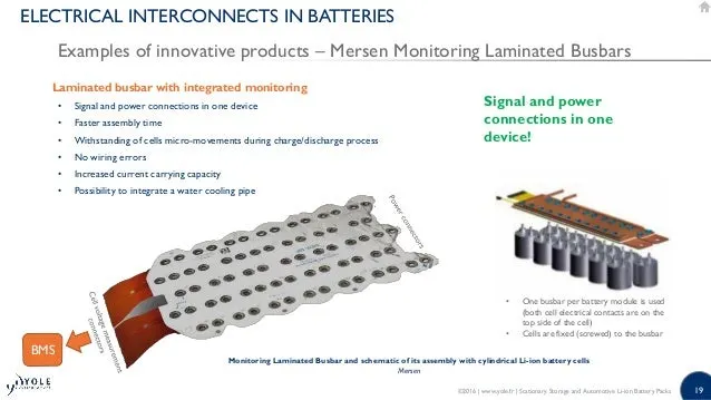
Size cell interconnects for the expected maximum current carrying capability. Improperly sized tabs
could heat up excessively, resulting in even higher resistivity. For reliable welded connections at the
terminals, A123 Systems recommends either pure nickel tabs or nickel-clad copper tabs. In addition,
other alloys afford both the weldability, strength and low resistance, which are all desirable features
of a good interconnection. Cell interconnects (tabs) should be neither soldered on the end caps nor
attached using extreme heat. A123 Systems recommends tabs be resistance or laser-welded to both
ends of the cells. Resistance welding provides a constant current for a specified period of time
through a salient feature in the weld tab. These parameters can be specified and regulated for a
consistent high-quality weld every time.
Allowing the Cell to Vent in a Fault Condition:
The cell vents, located on the end cap(s) of the cells (on the POSITIVE side of the cell), should not be
blocked by any mechanical means. Blocking the cell vent and then sufficiently abusing the cell so as
to build up pressure in the cell prevents the cell from properly venting. An ESS designed to install
cells end-to-end needs at least 1 mm of space between the cells to allow the vent to open under
fault conditions. Refer to Figure,
8. Cell Insulation:
The outside case of the 26650 and 32113 is electrically connected to the positive end (cathode) of
the cell. Take care to keep this surface electrically-isolated from any electrical bus bar or mechanical
support that may be of different voltage potential. Insulation, such as tapes, shrink wraps, or
sleeves, must have at least a 150 °C melting point. This helps ensure that the cells do not short
circuit to each other in a high temperature fault condition, which could cause even more widespread
damage. Cell Support Secure the cells in place by supporting their outside cases, not their terminal
ends. The vibration induced between the terminal ends and the rest of the case has been shown to
be detrimental to the life of the cell, causing internal and external cell damage. The intercell
terminations must be light enough not to cause vibration-induced damage to the cell.
9. Cell Support:
Secure the cells in place by supporting their outside cases, not their terminal ends. The vibration
induced between the terminal ends and the rest of the case has been shown to be detrimental to the
life of the cell, causing internal and external cell damage. The intercell terminations must be light
enough not to cause vibration-induced damage to the cell.
10. Cell Protection:
In addition to being supported, protect cells from exposure to corrosive substances and oxidizing
catalysts, such as dust and moisture. The necessary level of protection for cells in a battery pack
varies depending on the intended application. For example, a battery pack designed for use in an
HEV must have an enclosure that isolates cells from shock and vibration, protects them from dirt
and debris, as well as shielding them from other environmental dangers, such as salt spray. Unless it
is hermetically sealed, even a sealed enclosure is subject to pressure differentials between its
insides and the ambient, causing minute amounts of air exchange. Therefore, over time, some
moisture may accumulate and condense on inside surfaces. An ESS designed to be sealed from the
environment (from dust, moisture, and VOCs) must have a way to benignly drain off whatever
condensate does manage to leak into it. In addition, enclosures protecting cells must work with the
thermal management system to achieve optimum durability and safety of the battery pack. For
example, a poor choice of materials for the enclosure, combined with insufficient cooling and
controls, may cause the battery pack to overheat.
11. Thermal Management:
A123 Systems’ cells operate throughout a wide temperature range; however, they are most
effective between 10°C and 50°C. The temperature differential between the coolest cells and the
hottest cells should be no more than 10°C. Careful attention to thermal management is necessary to
keep the cells operating at peak efficiency and avoiding fault conditions. In most cases, this implies
a cooling system. There are certain applications - such as HEV vehicles operating in cold climates -
where a heater isbeneficial to keeping the cells operating in their optimal range.
12. Electrical:
When joining cells together, A123 recommends using a Battery Management System responsible for
carefully monitoring cell voltage, current, and impedance. The BMS may be implemented as discrete
circuitry or through a microcontroller.
13. Cell Monitoring:
To ensure optimal performance, safety, and durability of the pack, the Battery Management System
must monitor the voltage of each individual series cell in a battery string.Take care to place the
voltage monitoring connections in such a place that they are not affected by high currents going
through the interconnection elements. The diagram below depicts an optimal positioning of the
voltage monitoring contact points in an idealized setting:
In this case, Vm1 = Vcell1 – 2 x i x Rs and Vm2 = Vcell2 – 2 x i x Rs. The result of Vm1 – Vm2
would be exactly what is desired, and that being Vcell1 – Vcell2.
If the contact points are placed asymmetrically, such as shown below:
Vm1 = Vcell1 – 3 x i x Rs and Vm2 = Vcell2 – i x Rs. The result of Vm1 – Vm2 would contain an
undesirable offset in it: Vcell1 – Vcell2 + i x Rs where Voffset = i x Rs.
This offset in the voltage readings would cause the BMS to read that there is more charge in one cell
while the current is flowing in one direction, and have less charge in it while current is flowing in the
opposite direction. So while the battery is discharging, the BMS would balance some of the cells, and
while it is recharging, the BMS would balance the others. This results in a great deal of wasted heat
and energy that contributes to a reduced performance and sevice lifetime of the battery. Ensure that
balancing currents do not share the voltage sensing leads. Otherwise, the balancing currents will
affect the voltage reading proportionally, increasing the time needed to achieve proper cell
balancing, if not making it impossible.
The following circuit depicts a condition in which the measured voltages would be affect by balancing
currents going through the sense leads:
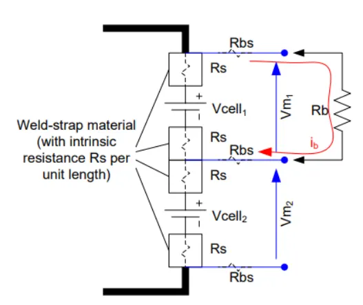
In such a case, if Rb were connected to cell 1, Vm1 would read Vcell1 – ib x 2 x (Rbs + Rs). Having
a separate wire for balancing current from the sensing wires eliminates a good portion of the error.
14. Nickel Strips:
Conductive metal strips were spot welded betweeen all the cells in battery pack.Nickel is used due
to its low relative resistance and ease of spot welding.
Battery Pack Production line
Model of Battery Pack
Assembly of the battery pack
Battery pack components are given as follows;
1. 2200 cells
2. Nickel strip
3. PVC heat sink film
4. spot welder
5. Connected
6. Cell holder
7. Solder
Step 1 -
The first step is to start snapping the square cell holder together. One can use the cell terminal block
but they will take more space than a hexagonal block.
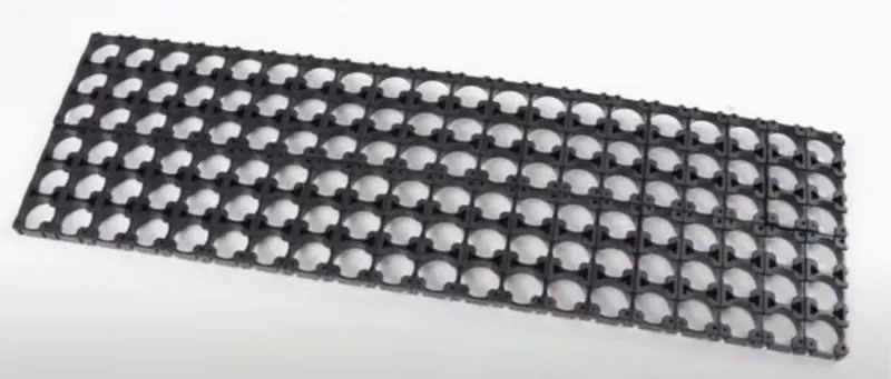
this is the cell holder block.

This image shows the insulate gasket.
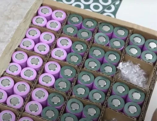
Step 2 -
Placing the cells in the holder matrix. Place all the cells in the holder and put the second holder in
the place.
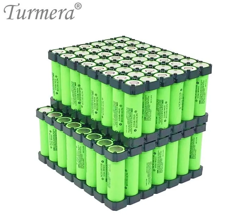
Step 3 -
Now we will be connecting the cells with nickel strips using the spot welding process. The series
connection will be made by connecting the positive terminal of the cells to the negative terminal.
The parallel connection will be made by connecting the same terminal.
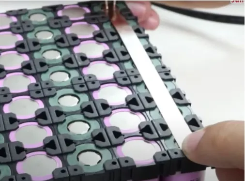
Connecting the complete matrix of the cell together.
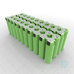
Step 4 -
Connecting the heat sink to the battery pack
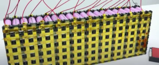 ]
]
Now we will be soldering the battery wire
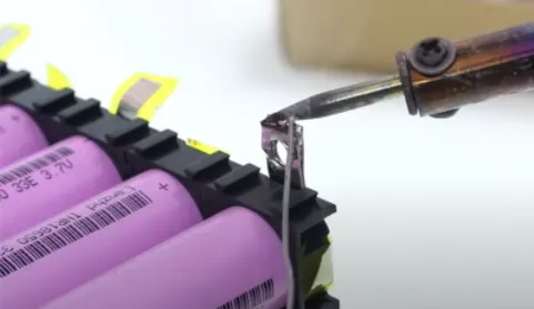
Now the internal structure of the battery pack is assembled and all the terminals are connected as
per the connections.
Step 5 -
Connect the balancing wire pin to the battery management system.

Step 6 -
After the battery management system, the next and final step is to place the enclosure for the
battery pack.
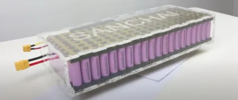
This is the final battery pack model created.
Applications:
1. Energy storage
2. Uninterruptible Power Supplies
3. Communication technologies
4. Aerospace
5. Electrified mobility devices
6. Industrial equipment
7. Medical devices
8. Toys
Conclusion:
1. The design calculation for the battery pack was carried out and calculated.
2. The steps involved in the making of the battery pack are explained briefly.
PDF file:
https://drive.google.com/file/d/1CpAWqY9KR2txRNDfmMag60MCL4vOL_oS/view?usp=sharing