Project 1
Aim:
To design a Battery pack for an electric Vehicle (Car).
Objective:
Battery Pack Capacity = 150 Kw
Rated voltage of a Battery = 120 V.
Cell Nominal capacity = 3500 mAh
Nominal Cell Voltage = 3.6V
Theory:
Electric Vehicle Battery Pack- Design, Components and Packaging:-
Lithium-ion batteries are highly efficient and more reliable than other batteries making them a good
choice for electric vehicles. Despite the batteries being highly rated, some of the main deterring issues
they face include; the thermal stability of Li-Ion batteries and high manufacturing costs. Many players
and car manufacturers in the electric vehicle industry are today focused on optimizing battery designs.
The main result most of them strive to achieve is to have batteries with increased energy storage that
are safe, light in weight, and highly efficient. Most manufacturers aim to produce batteries that have
regulated thermal conditions to improve the performance of EV battery packs.
Fig. LiFePO4 battery Cell
3.2 V 20A Low Temp LiFePO4 Battery Cell:
-40℃ 3C discharge capacity≥70%
Charging temperature:-20~45℃
Discharging temperature: -40~+55℃pass acupuncture test
-40℃ maximum discharge rate:3C
Electric Vehicle Battery Pack design
Electric vehicles' car battery packs have a complex system that consists of various components.
Therefore, an efficient battery pack design is crucial for the success of an electronic vehicle. An EV
battery pack contains various electro-mechanical systems that communicate with different sub-
systems within the car. They also communicate simultaneously with multiple parameters through
various interfaces. These interfaces include; mechanical, structural, thermal, electrical, control, and
support.
1] Mechanical Communication through the various interfaces influences the reliability and safety of the
battery pack, making it safer to drive an EV. It represents all the mechanical design features of an EV.
These include damping pads, exhaust valves, cell spacers, and different seals that have been
integrated within the battery pack for safety reasons.
2] Structural- it is the general containment of the battery pack. It contains structural features such as
tie-rods, end-plates, and cross-members that function as protective members in the battery pack.
Therefore, a good battery pack has to have a case and a cover to prevent it from external and
environmental factors (humidity, dirt, vibrations, and crash effects).
3] The thermal interface controls the temperatures within the Lithium-ion battery cell between 25 and
30 degrees Celsius. It also ensures there is uniform thermal distribution within the battery pack to
maximize energy capacity. It contains systems such as pumps, heat exchangers, coolants, and fans.
4] The electrical interface generates and transmits a certain voltage to meet the power requirements
of an EV. Its electrical circuit consists of a bus bar and cables, fuse, contactors, circuit breaks, and
relays.
5] Control systems monitor and regulate the state of a battery pack. The features are the Battery
Management System and sensors used to measure current, voltage, humidity, pressure, and
temperature within a battery pack.
Fig. Low Temperature High Energy Density Battery
Rugged Laptop Polymer Battery:
Battery specification: 11.1V 7800mAh
-40℃ 0.2C discharge capacity ≥80%Dustproof, resistance to dropping, anti - corrosion, anti -
electromagnetic interference
6] Support interface is the support the battery pack gets from the vehicles. It is commissioned through
mounting brackets and axles to help achieve the required degree of vibration isolation. Other systems
include the chassis, floor, and car seats.
Electric Vehicle Battery Pack Components
An electric vehicle needs an enormous amount of power to perform effectively. An EV battery pack
may vary slightly depending on the type of electric vehicle. But generally, these vehicles' battery packs
contain three components; cells, modules, and a pack. An EV contains countless batteries that are
installed in the form of modules and packs. Therefore, a cluster of battery cells does a module; a
cluster of modules makes a pack, and hence the word battery pack.
A] Cell
A cell is a basic unit that exerts electrical energy by charging and discharging to propel an EV. A cell is
made of cathode, anode, separator, binders, and an electrolyte, all encompassed in an aluminum case.
The cathode is the positive electrode that typically holds the most valuable recyclable material that is
made up of many metals such as cobalt, aluminum, nickel, etc. On the other hand, the anode, which is
a negative electrode, is composed mainly of silicon-based components, carbon or graphite.
B] Module
A module is an assembly of battery cells put in a frame by combining a fixed number of cells to protect
them from external factors like heat, shock, or vibrations. Modules are welded together to complete
the electrical current flow path within an EV. These modules can also incorporate temperatures and
cooling mechanisms and monitoring of the voltage produced by each battery cell.
C] Pack
A pack is the final shape of an EV battery. It is composed of modules and various control systems,
including the Battery Management System, thermal management system, etc.; these control systems
are responsible for communications with the vehicle outside the battery pack.
Electric Vehicle Battery Pack Packaging
An EV battery pack should be reliable and address issues that relate to impact resistance, thermal
stability, and vibration isolation. While packaging a battery pack, there should be minimized
mechanical and thermal interactions between the different units of a battery pack system to reduce
the probability of the battery failing. There are critical factors and systems within a battery that have
to be considered during packaging. These include the battery cell, gas exhaust nozzles, cell spacer
type, insulation coating thickness, and the battery cooling system. These factors are crucial as they
are the systems that make an EV operate safely and efficiently.
When it comes to packaging, the battery cell type is significant. Research proves that it is easier to
improve the volumetric efficiency of a pack by packaging large quantities of smaller cylindrical cells.
Packaging compactness has a positive impact on the thermal performance of a battery pack. The
battery cell spacer type is also important in packaging. The battery cells are usually held together in
their pre-specified places by rigid spacers. These spacers are friction fit and always depend on the type
and shape of cells used. They are meant to be a right fit to restrict the movement of a battery cell or a
module undergoing thermal regulation fluctuations.
The battery pack packaging also includes a thermal management system. A pressure release valve is
included in the packaging to minimize the safety risk posed to the EV in case of a battery failure due to
high temperatures.
Calculations:
1. Design the battery pack configuration.
Here , Battery Pack = 150 Kw
Battery Voltage = 120 V
Cell nominal capacity = 3500 mAh = 3.5 Ah
Cell nominal Voltage = 3.6 V
As Battery power and a Battery Voltage is given, we can Find out Battery Current
As we know that ;
P = V X I
P = Battery power
V = Battery voltage
I = Battery Current
Therefore,
I battery = P / V
= 150000/ 120
Battery current = I = 1250 Amp
Maths for cells in Battery
No. of Cells in Series = Battery voltage / Cell Nominal Voltage
Battery voltage = 120 V
Cell nominal Voltage = 3.6 V
No. of Cells in Series = 120 / 3.6
No. of cells in Series = 33.3333 = 34
With the help of No.of cells in series and cell nominal voltage we can calculate Battery Nominal
Voltage.
Formula:
Battery Nominal Voltage = No. of cells in series X Cell nominal Voltage
Battery Nominal Voltage = 34X 3.6
Battery Nominal Voltage = 122.4 V
Formula for Maximum Battery Voltage :
Battery Maximum voltage = Cell Maximum voltage X No. of Cell in Series
Vmax battery = 120
No. of cells in Series = 34
Cell maximum Voltage = 120 / 34
Cell Maximum voltage = 3.53 V
we know,
Battery Cell Energy = Cell nominal capacity X Cell Nominal Volatage
Battery Cell Energy = 3.5 Ah X 3.6 V
Battery cell Energy = 12.6 Wh
Maths for cells in Battery
No. of Cells in Parallel = Battery Current / Cell nominal Capacity
Battery Current = 1250 Amp
Cell nominal capacity = 3.5 Ah
No. of cells in parallel = 1250/ 3.5
No. of Cells in Parallel = 358
For the configuration of Battery Pack we have,
1.No. of Cells in series = 34
2.No. Of cells in Parallel = 358
3. Battery Voltage = V = 120 V
4. Battery Current = I = 1250 Amp
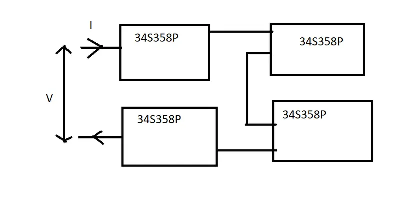
Fig. Battery pack Configuration
How Electric Vehicle battery Packs are Manufactured:
EV battery packs possess many traditional machine components. EV battery pack manufacturing
processes, in particular, rely heavily on a variety of machine components including MISUMI
components which are present at every step in the fabrication process.
The Battery Cell is a small, rectangular component roughly the geometry of a paperback book. These
battery cells are assembled together in frames to form Battery Modules. These modules are then
linked together via a myriad of electrical connections and enclosed in the Battery Pack which is
assembled directly to the automobile frame. The following arrow diagram below is a compass to
understand the process terminology.
Battery Cells -> Battery Modules -> Battery Pack

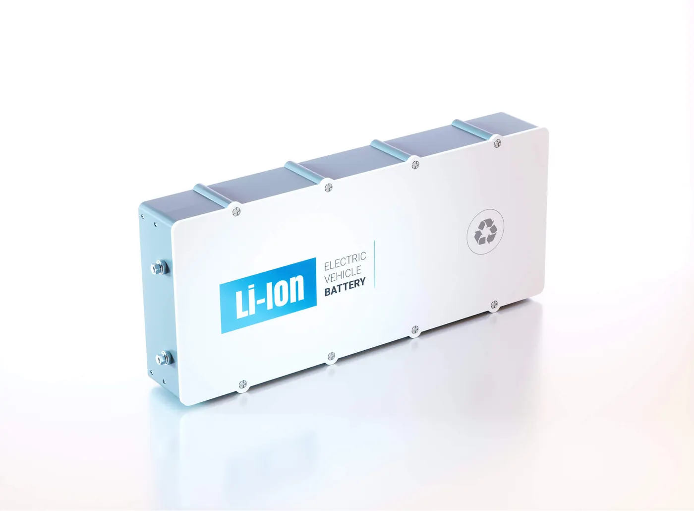
Battery Cell Battery Module
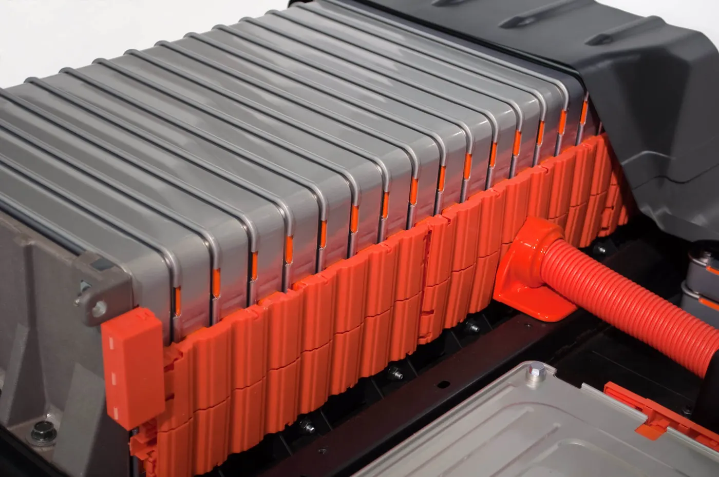
Battery Pack
The process outlined in this topic will begin with taking the battery cells out of packaging. This
topic will discuss the fabrication process using the battery cells as the “raw material” in the battery
pack fabrication process. These small individual cells are typically manufactured at other, specialized
facilities and arrive at the automobile fabrication plant as completed products. This workflow is the
vision for the vaulted Tesla Gigafactory in Nevada which will produce all the battery cells required for
the Tesla’s automotive assembly facilities.
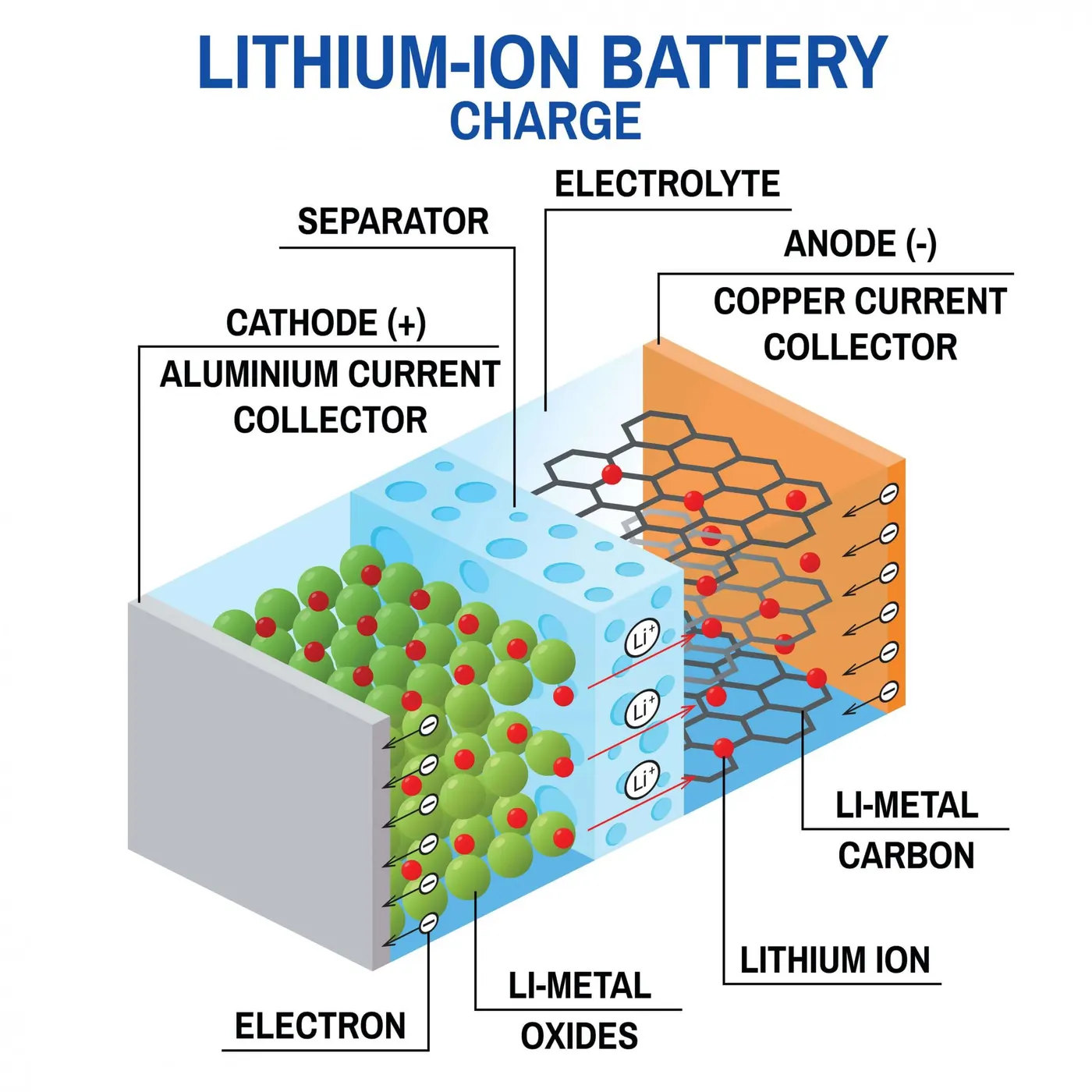
Fig. Lithium-ion battery schematic
Before the cells can be assembled into modules, each cell undergoes checks within a specialized
fixture. This process is essentially a “leak check” process to ensure that the electrolyte isn’t leaking
from the cell and to ensure that no moisture intrusion occurs over the entire operational life of the
battery. This step is vitally important to ensure that the cells are properly functioning, and future
battery capacity won’t be compromised.
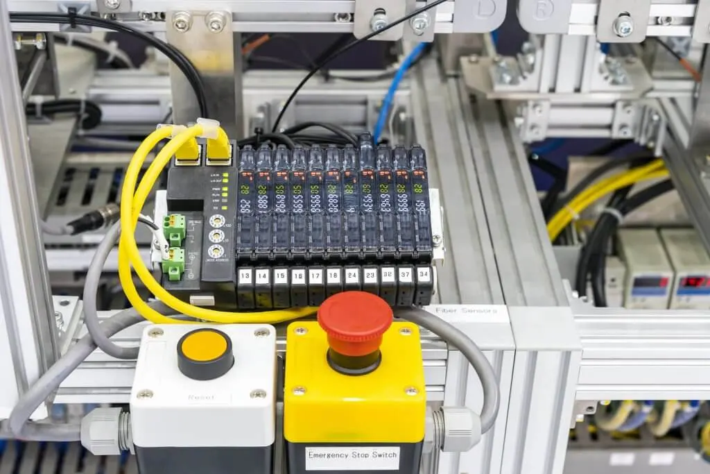
Fig. EV Battery Assembly Fixture
The machine components that unpack the battery cells from packaging are comprised of many
components such as power cables, roller conveyors, rotary shafts and linear ball bushings.
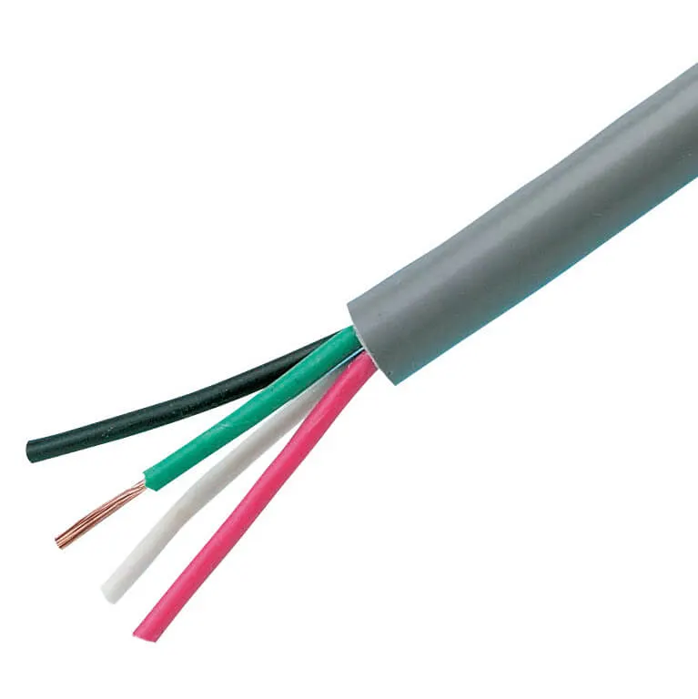
Power cables


Roraty shafts Linear Ball Bushings
The fixtures that check the battery cells are also comprised of dozens of components such
as aluminium extrusions, configurable mounting plates, timing belt/pulley systems, circular cordsets
and circular connectors.


Configurable plates Timing belts& pulleys Circular cordsets
The next step in the process involves assembling the battery cells into battery modules. Typically,
there are about 12 battery cells per battery module, but this varies across automotive make and
model. The modules stack within a metallic frame. This frame comprises the module housing and
protects the cells from physical shock loads.
This assembly process is highly automated and involves many MISUMI configurable machine
components. The most visible of these components are the timing and conveyor belts which run the
workpieces through the process.

Conveyor timing belt
The last step in battery pack fabrication is assembling the modules into the battery pack housing. This
step involves a significant number of electrical hookups and fine-tuning. For example, the Nissan Leaf
EV contains 48 battery modules which are all connected together via electrical monitoring equipment.
These modules are typically picked and placed by an automated robotic assembly arm into the battery
pack housing. After all the modules are placed into the housing they are manually connected together
by an automotive technician. After all connections have been made, the battery pack housing cover is
placed manually; finally, an automated robot arm is typically used to drill all screws thus completing
the battery pack fabrication process.
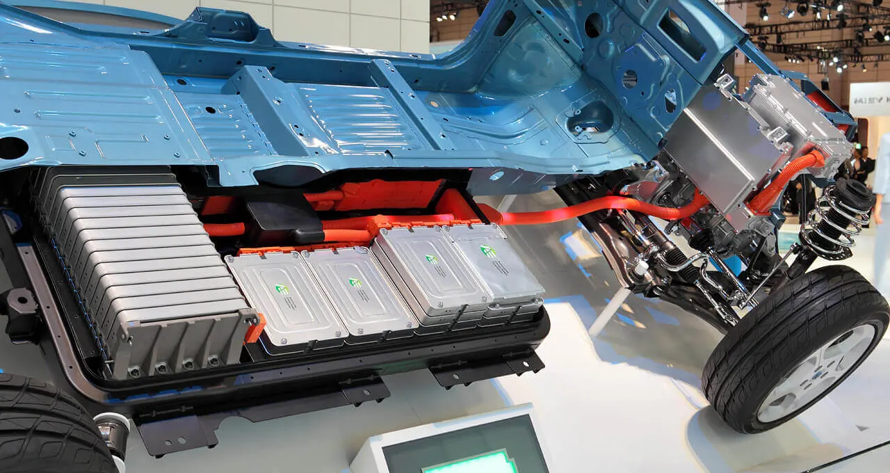
Nissan leaf
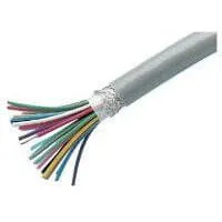
The MISUMI components that are typically employed in this final step involve control and
instrumentation cables, sensor cordsets, angle brackets, locating pins, shims and spacers and pressure
gauges.


Control & Instrumentation Angle brackets Pressure Gauges
cables
From this step, the completed battery pack is ready to be assembled into the automotive frame.
2. Draw the BMS topology for this battery pack.
What is the Battery Management System (BMS):
BMS stands for the battery management system which is used to manage the lithium ion
batteries to prevent it from the overcharging, discharging, and to maintain balance charging. It
provides the protection from the short circuit. Let suppose if we have four lithium cells and we
connect it in series and if we want to charge it, one cell will charge quickly other cell will charge late
due to which proper combination will not be obtained. Due to which we will not get stable voltage at
the output. In this case we make use of BMS module.
Constant monitoring System:
The battery needs the constant monitoring because the battery pack is made up of tiny cells connected
in parallel and series combinations.
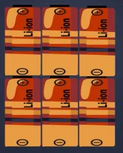
These tiny cells are very dumb and highly unstable; the voltage across the cells has to be precisely
monitored or balanced. If we don’t do so then we can end up destroying the battery pack and safety of
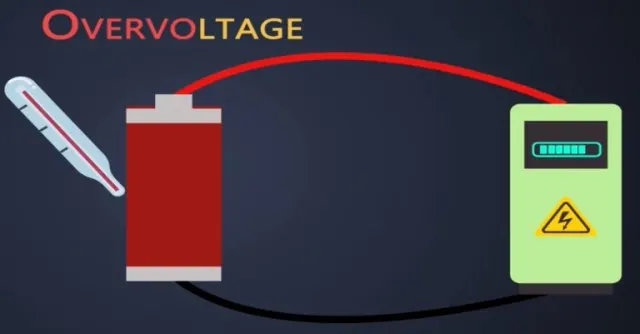
the whole electric vehicle might compromise. When a battery is charging we have to apply
the voltage and current to it. if this voltage is more than specified limit mentioned in the datasheet
then it is considered that the battery is charging with over voltage which will eventually increase the
temperature of the battery.
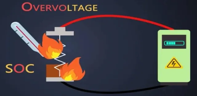
Every battery has a specific range of temperature in which the battery works fine. So if this
temperature increases which ends up reducing the state of charge this condition also increases the
internal resistance of a battery and eventually the power loss across the battery increases. On the
other hand if the voltage applied to this battery is lower, then also it will lead to over
temperature over-voltage and under-voltage lead to a temperature which degrades the battery life
and if we use the battery at a temperature lower than its specific range then its capacity decreases
due to over temperature the batteries might catch fire as well.
There are always slight differences in the state of charge, discharge rate, capacity, and impedance
between two cells. Even if the cells are from same manufacturer and produced in the same lot. While
charging or discharging these cells altogether some cells experience a lot of stress in battery pack so
they lead to degradation well to avoid all these scenarios we have to monitor over voltage and under
voltage limit of the battery. We have to keep a close watch on battery temperature and we have to
ensure that the charge level of each battery stays within the recommended associate range by
balancing every cell. So the efficient and effective way to maintain a close watch on this tiny cells a
fast and smart battery management system has to be used. BMS can monitor all of this and provide
real-time diagnostics.
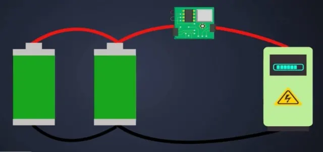
Now let's see how BMS helps to keep these batteries healthy:
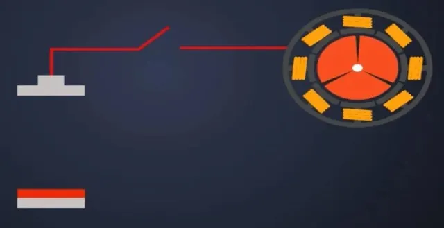
Discharge Control:
First is the discharge control the primary goal of a BMS is to keep the battery away from operating out
of its safety zone. The BMS must protect this cell during discharging.
State of determination:
Second is the state of charge determination one of the features of the BMS battery management
system is to keep the track of SOC of the battery. The SOC indicates the user about current
capacity of the battery. There are several methods to determine SOC.

The SOC can be determined through:
1. Direct voltage measurement
2. Coulomb counting
3. The combination of Coulomb counting and voltage measurement
There are tons of different methods but for simplicity we will see the voltage measurement and
Coulomb counting method to measure the associate directly.
Direct Voltage Measurement:
We can simply use a voltmeter because the voltage decreases more or less linearly during the
discharge cycle of the battery. So if the voltage decreases the associate of the battery also decreases.

Coulomb counting:
In the Coulomb counting method the current coming in or going out of a battery is measured over
time to calculate the relative amount of charge. It is like pouring water into water tank and fetching it
out, imagine the battery as a jar and water is like electrical energy or charge.
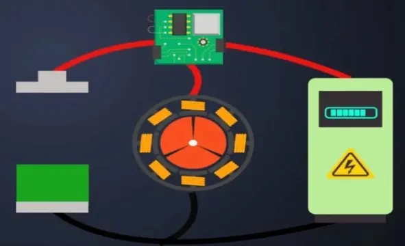
The BMS battery management system measures how much current is going inside the battery and
calculates the charge deposited inside the battery overtime.When the calculated charge is near to the
rated capacity of the battery then BMS informs that battery is fully charged and while it is charging it
follows the same process.
Combination of Coulomb, Counting and Voltage measurement:
In addition this both methods could be combined, the voltmeter could be used to monitor the battery
voltage and calibrate the SOC when the actual charge approaches at the end.
State of health determination:
It is batteries ability to store charge and deliver electrical energy compared with a new battery, any
physical parameter of a battery such as internal resistance or conductance changes significantly with
age can be used to indicate the soh of the cell. In practice the soh could be estimated from by the
internal resistance or the cell conductance as the battery gets older the internal resistance of the
battery increases.
Cell balancing:
It is a method of compensating weaker cells by equalizing the charge on all cells in the chain to extend
the overall battery packs life in the whole battery pack, small differences between the cells due to
tolerances or operating conditions you rise to uncertainties.
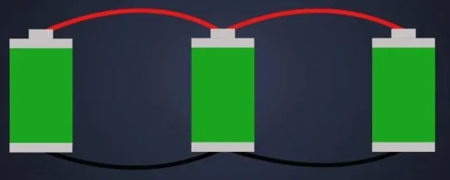
During charging weak cells may get over stressed and become even weaker until they eventually fail
which causes the whole pack to fail prematurely. So to avoid this BMS battery management
system has to provide cell balancing. Majorly there are two cell balancing techniques first is
the active balancing second is the passive balancing.
LOG book:
BMS also has to work as a log book because the soh of a battery is a relative term it compares the
new battery and old battery. So this measurement should hold a record of the initial conditions of a
cell and should be able to compare with the same cell as it gets old. So the log book function of
the MEMS would record such important data into the memory.
Communications:
BMS provides information about health SOC along with much more details for service and
maintenance. In general the user who is driving the vehicle is not a technical guide. So the information
should be simple an interpretable. On the other hand the battery service technicians or engineers
demand very precise technical information for research or fault detection and its BMS job to provide
the necessary data to both of them. So this all things a BMS should do for safety of the battery well.
The benefits of battery management systems:
An entire battery energy storage system, often referred to as BESS, could be made up of tens,
hundreds, or even thousands of lithium-ion cells strategically packed together, depending on the
application. These systems may have a voltage rating of less than 100V, but could be as high as 800V,
with pack supply currents ranging as high as 300A or more. Any mismanagement of a high voltage
pack could trigger a life-threatening, catastrophic disaster. Consequently, therefore BMSs are
absolutely critical to ensure safe operation. The benefits of BMSs can be summarized as follows.
1. Functional Safety. Hands down, for large format lithium-ion battery packs, this is particularly
prudent and essential. But even smaller formats used in, say, laptops, have been known to catch fire
and cause enormous damage. Personal safety of users of products that incorporate lithium-ion
powered systems leaves little room for battery management error.
2. Life Span and Reliability. Battery pack protection management, electrical and thermal, ensures
that all the cells are all used within declared SOA requirements. This delicate oversight ensures the
cells are taken care of against aggressive usage and fast charging and discharging cycling, and
inevitably results in a stable system that will potentially provide many years of reliable service.
3. Performance and Range. BMS battery pack capacity management, where cell-to-cell balancing is
employed to equalize the SOC of adjacent cells across the pack assembly, allows optimum battery
capacity to be realized. Without this BMS feature to account for variations in self-discharge,
charge/discharge cycling, temperature effects, and general aging, a battery pack could eventually
render itself useless.
4. Diagnostics, Data Collection, and External Communication. Oversight tasks include
continuous monitoring of all battery cells, where data logging can be used by itself for diagnostics, but
is often purposed to the task for computation to estimate the SOC of all cells in the assembly. This
information is leveraged for balancing algorithms, but collectively can be relayed to external devices
and displays to indicate the resident energy available, estimate expected range or range/lifetime based
on current usage, and provide the state of health of the battery pack.
5. Cost and Warranty Reduction. The introduction of a BMS into a BESS adds costs, and battery
packs are expensive and potentially hazardous. The more complicated the system, the higher the
safety requirements, resulting in the need for more BMS oversight presence. But the protection and
preventive maintenance of a BMS regarding functional safety, lifespan and reliability, performance and
range, diagnostics, etc. guarantees that it will drive down overall costs, including those related to the
warranty.
BMS Topologies:
Modern BMS systems for EV applications are typically distributed electronic systems. In a standard
distributed topology, routing of wires to individual cells is minimized by breaking the BMS functions up
into at least two categories. The monitoring of the temperature and voltage of individual cells is done
by a BMS sub-module board, which is mounted directly on each battery module stack. Higher level
functions such as computing state of charge, activating contactors, etc. along with aggregating the
data from the sub modules and communicating with the ECU are done by the BMS main module.
The sub-modules and main module communicate on an internal data bus such as controller area
network (CAN). Power for the BMS can be supplied by the battery stack itself or from an external
primary battery such as a standard 12V lead acid battery. In some cases, the main module is powered
externally, while the sub modules are powered parasitically from the battery modules to which they
are attached.
There are 4 types BMS Topologies.
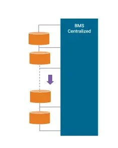
1] Centralized BMS Architecture
Has one central BMS in the battery pack assembly. All the battery packages are connected to the
central BMS directly. The structure of a centralized BMS is shown below . The centralized BMS has
some advantages. It is more compact, and it tends to be the most economical since there is only one
BMS. However, there are disadvantages of a centralized BMS. Since all the batteries are connected to
the BMS directly, the BMS needs a lot of ports to connect with all the battery packages. This translates
to lots of wires, cabling, connectors, etc. in large battery packs, which complicates both
troubleshooting and maintenance.
2] Modular BMS Topology
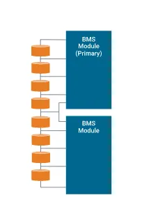
Similar to a centralized implementation, the BMS is divided into several duplicated modules, each with
a dedicated bundle of wires and connections to an adjacent assigned portion of a battery stack. As
shown in below figure. In some cases, these BMS submodules may reside under a primary BMS
module oversight whose function is to monitor the status of the submodules and communicate with
peripheral equipment. Thanks to the duplicated modularity, troubleshooting and maintenance is easier,
and extension to larger battery packs is straightforward. The downside is overall costs are slightly
higher, and there may be duplicated unused functionality depending on the application.
3] Master/Slave BMS Topology
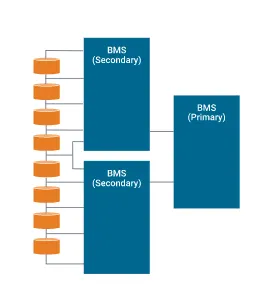
Conceptually similar to the modular topology, however, in this case, the slaves are more restricted to
just relaying measurement information, and the master is dedicated to computation and control, as
well as external communication. So, while like the modular types, the costs may be lower since the
functionality of the slaves tends to be simpler, with likely less overhead and fewer unused features.
4] Distributed BMS Topology
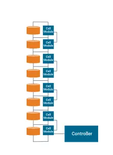
Considerably different from the other topologies, where the electronic hardware and software are
encapsulated in modules that interface to the cells via bundles of attached wiring. A distributed BMS
incorporates all the electronic hardware on a control board placed directly on the cell or module that is
being monitored. This alleviates the bulk of the cabling to a few sensor wires and communication wires
between adjacent BMS modules. Consequently, each BMS is more self-contained, and handles
computations and communications as required. However, despite this apparent simplicity, this
integrated form does make troubleshooting and maintenance potentially problematic, as it resides
deep inside a shield module assembly. Costs also tend to be higher as there are more BMSs in the
overall battery pack structure.
Out of the 4 topologies, For the Battery pack configuration for a car we are using Master/Slave
Topology. This topology is widely used topology for the 4-wheeler. Other topologies are generally
used for 2 and 3-wheeler . Lets know detail about Master/Slave topology in detail.
Nowadays, electric vehicle usage and the use of LiFePO4 batteries in electric vehicles gradually
increase. However, there are important features to be considered to use these batteries safely and
efficiently. Incorrect use of these batteries can lead to burning, explosion or shortening of the life of
batteries. In this paper, a Battery Management System (BMS) for lithium based batteries is designed
that operates more efficiently and communicates with UART between master and slave modules and
can communicate via CAN protocol with external devices. Micro controller based control and protection
equipment is designed that help to measure and monitor the voltage, temperature and current values
of the batteries. They protect the battery cells from the conditions such as over charge, over
discharge, high current, high temperature. BMS balances battery cell voltages during charging process
with passive cell voltage balancing. In addition to the main controller module in the BMS, slave
controller modules have been added to provide high resolution voltage and temperature tracking. A
modular BMS has been devised which can be used in groups of batteries of different voltage values
thanks to electrically isolated slave control modules.
Fig. BMS network topology diagram
Flowchart of Master/Slave topology for the main controller:
Designed BMS Slave module:
Fig. Slave module block diagram
Main Controller module block diagram:
Master Module Structure:
Slave module structure:
Master-Slave architecture:
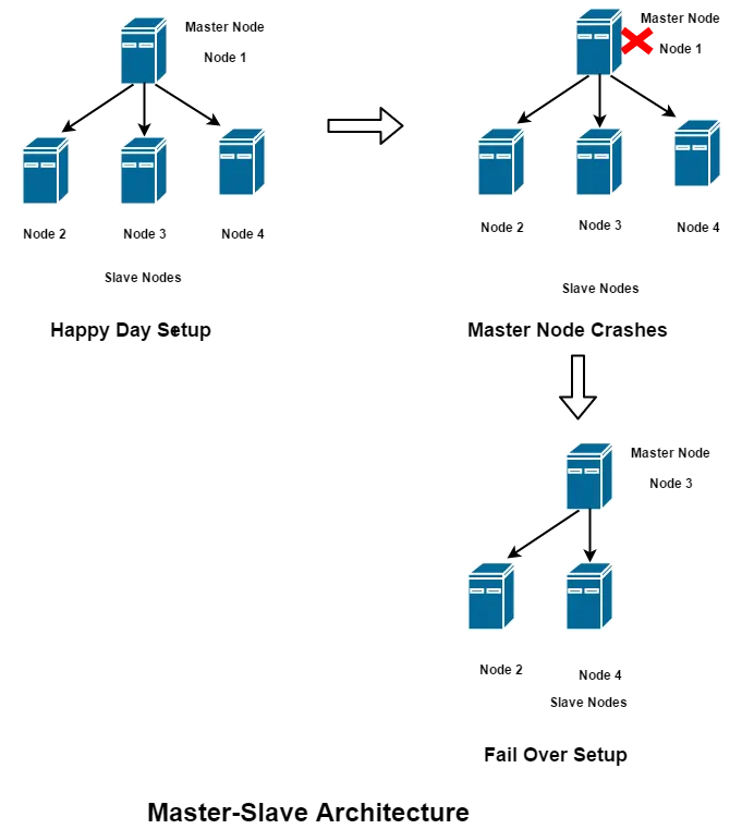
In software architecture, Master/Slave defines a type of architecture in which we have one master
node and several slave nodes, with the master exerting total control over the slave nodes. Also, the
direction of communication in this architecture is always from Master to Slave (However, this may not
apply in failure conditions).
The master node could control the following factors (this list is just a sample):
1. Communication protocol
2. Tasks assigned
3. Directions on when to act upon some task
Challenges:
Being Fault tolerant:
Let us imagine a scenario in which; the master node fails (refer above diagram). It would have a
catastrophic impact on the system, since all the slaves are dependent on the master node for
directions.
In such a scenario, we can have an arrangement wherein, when the master node fails, one of the
slaves would take over as master without impacting the system. For example, in the above diagram,
when the master node crashes, Node 3 is elevated as Master node.
How is the Slave node chosen?
1. Through configuration. i.e., preconfigure a slave node to act as master
2. Through voting. i.e., initiate a voting process amongst the slave nodes to choose the master
candidate.
To effectively implement the above fail over strategy, the slave node should be aware of the state of
the master before it went down. i.e., it should periodically synchronize the master’s state with itself.
The time period of synchronization would depend on the use case and the criticality of the system
being built.
Conclusions:
Electric vehicle battery packs have to follow certain considerations when manufacturing and packaging.
Manufacturers have to consider,
1. safety
2. Efficiency in terms of mass and volume, serviceability.
3. Readiness for harsh conditions operations, cooling system implementation, handling, and
operations.