Week-7 Challenge: DC Motor Control
Aim 1:
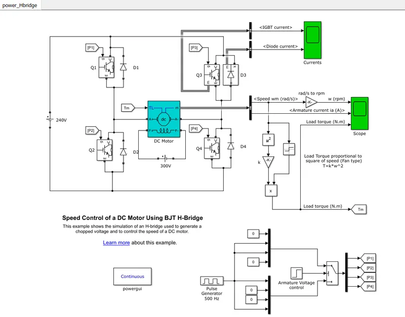
A] Explain a MATLAB demo model named ‘Speed control of a DC motor using BJT H-bridge’.
Solution: Speed control of DC motor using BJT H-Bridge.
This model shows the simulation of an H-bridge used to generate a chopped voltage and to control
the speed of a DC motor.
Explaination:
The most of the DC motor have two terminals because they are series type (armature and field windings
are connected in series) DC motor. please refer the figure given below.
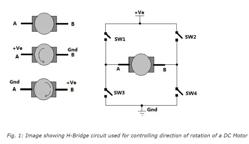
As shown in fig. there are two terminals 'A' and 'B' of a DC motor. Now if we connect terminal A
with +ve supply and terminal B with -ve supply or ground the current will flow from motor from
A to B and motor will rotate in one direction i.e. in forward direction or clockwise. Now as shown
in second figure we change the sypply terminals. Now B is connected with +ve and A is connected
to ground. The current will flow from motor from B to A and motor will rotate in the other direction
i.e. in reverse direction or counter clockwise.
The arrangement is shown in right side of the figure. 4 switches are connected in between +ve
supply and ground and DC motor is connected in between two switches as shown. Such circuit
arrangement is known as H-bridge because it look like letter 'H' (H-bridge circuits are most
widely used in DC motor drivers). Let us see how it gives reverse supply to the motor.
If SW1 and SW4 are pressed simultaneously then current will flow from +ve - SW1 - A - B
- SW4 - Gnd. So motor will rotate in one direction. open SW1 and SW4 to stop motor. Now
if SW2 and SW3 are pressed current will flow from +ve - SW2 - B - A - SW3 - Gnd. So
motor gets reverse supply and it will rotate in another direction.
( Caution: Care must be taken that SW1 and SW3 or SW2 and SW4 must not be pressed
simultaneously otherwise it will short circuit the supply.)
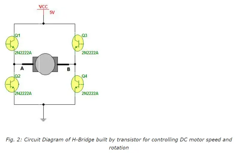
The circuit replaces the switches with NPN transistors. We all know that transistors works as switch.
For NPN transistors if we give +ve input to base it will turn ON and if we give 0 input it will be turned
OFF.
So in this circuit if Q1 and Q4 are turned ON simultaneously the motor will rotate forward and if Q2
and Q3 are turned ON then motor wil rotate reverse.
Motor can be rotated forward and reverse using 4 transistors only.
Let us move to vary thespeed of the DC motor. The DC motor speed varies as applied input voltage
varies. As we increase the applied input voltage the speed will increase and vice versa. Applying
max rated voltage will rotate motor at full speed.
One of the very popular method for generating variable DC voltage is pulse width modulation
(PWM). It is explained in figure given below.
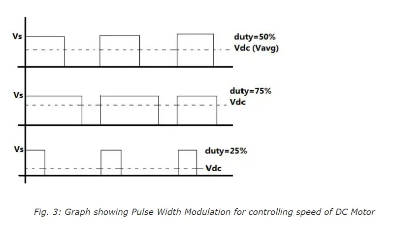
Pulse width modulation means varying the width (duty) of pulse. Width means ON time Ton of pulse.
The average output voltage (Vdc or Vavg) is given by equation,
Vdc = [Ton/(Ton+Toff)] * Vs
It directly depends upon Ton. As shown in fig. if duty is 50% the average output voltage Vdc is
exactly the half of Vs. if duty is increased to 75%, Vdc also increases to 3/4th of Vs and if duty
is decreased to 25%, Vdc reduces to 1/4th of Vs. Thus a pulse width varies the average output
voltage varies. So we have to apply PWM to DC motor to vary its speed.
B] Comment on the armature current shoot-up from the scope results.
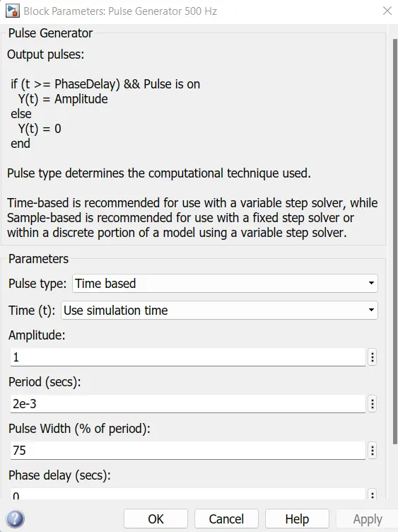
Case-1:The pulse width was set at 75 in the pulse generator.
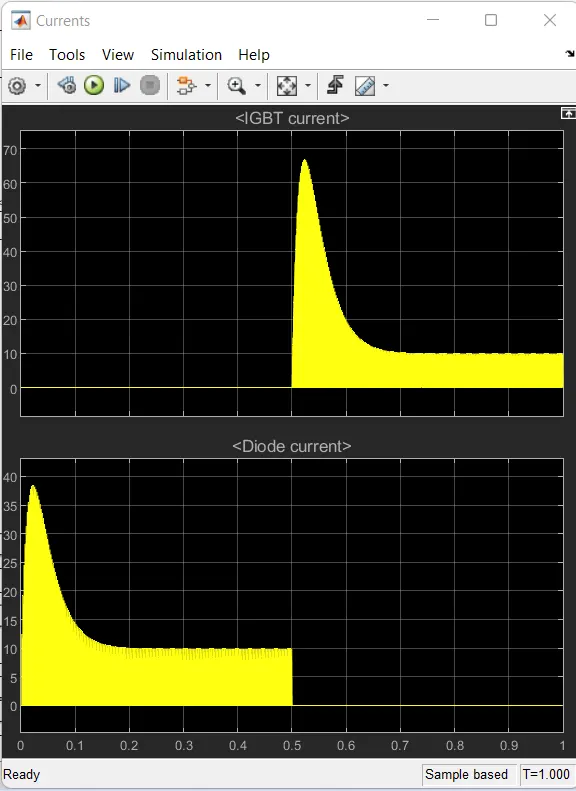
1. In the current, the amount of circuit acted is as shown as the graphical representation
during the period of duty cycles. The scope shows the IGBT current and diode current
passed in the quadrant Q3 and D3.
2. Where Q3 represents as IGBT current D3 is represented as diode current in scope.
3. The graph shows that when the switch Q3 is OFF on the starting stage of current
flow and diode current is on that stage.
4. During the 1 sec of time D3 switch is ON that are given according to the pulse generator
and after the time period of 1 sec D3 switch is OFF and IGBT current acted after 1 sec and
Q3 switch remains ON.
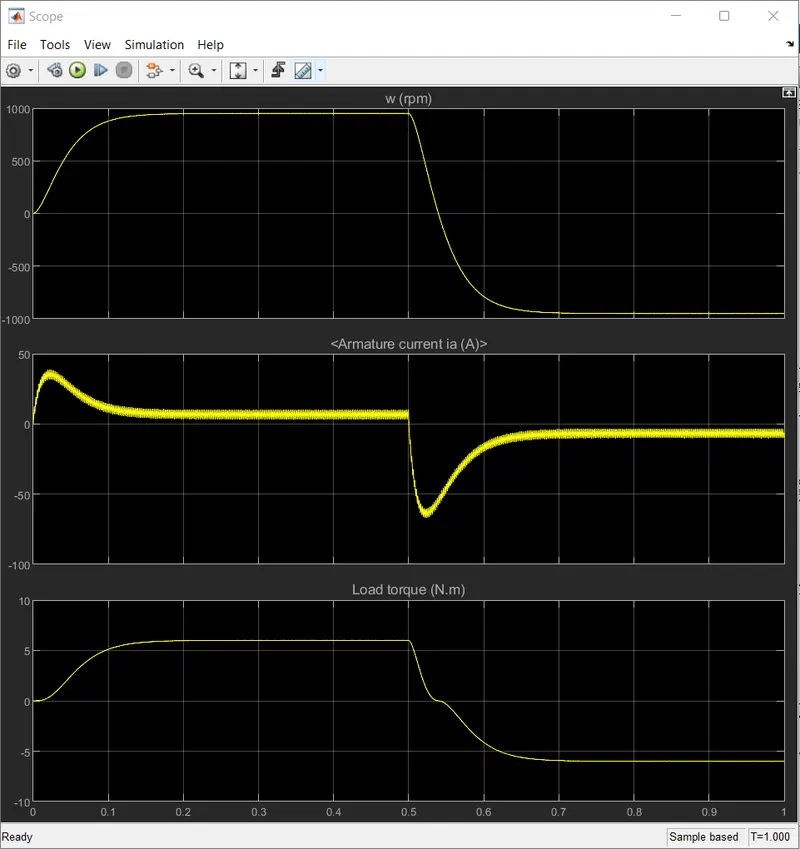
5. The speed and armature current is obtained by the DC motor and load torque is calculated by
torque proportional to the square of speed.
6. In the starting point, there is a sudden shoot-up in act.
7. This scope shows that speed is increased in a certain period of time and at that time armature
current is positive whereas load torque also moves forward.
8. After the time period of 1 sec which is given in pulse generator, sudden shoot up acted and speed
gets decreased in that time armature current is in negative terminal whereas torque act in reverse
action.
9. Here the sudden shoot-up is acted while armature current is processed at a positive and negative
terminal.
Case 2:
By changing the the pulse generator input value.
By changing the pulse width block parameter to 50%,
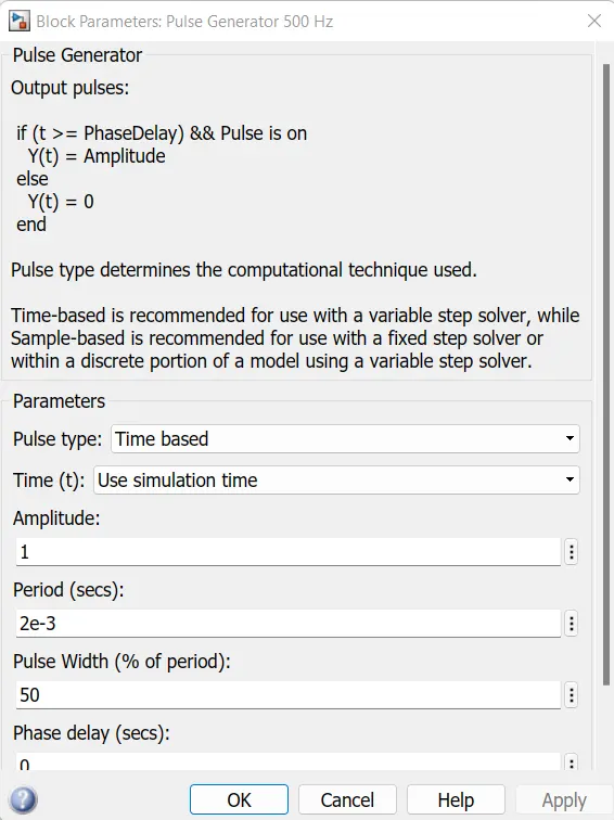
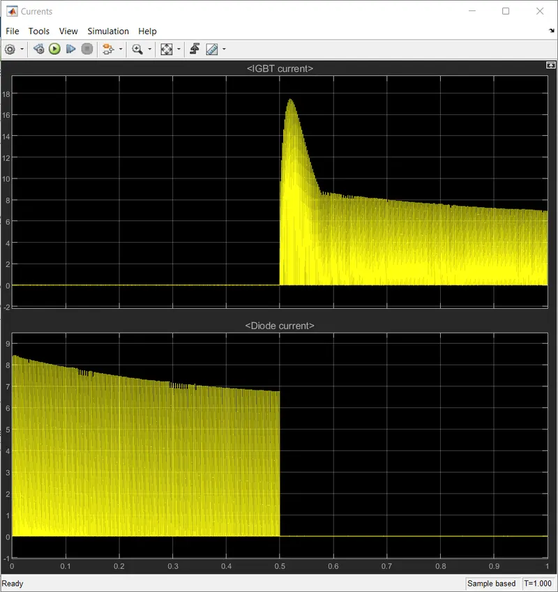
1. Here we can see that sudden shoot- up is not acted by comparing with 75 of pulse width . Same
cycle time is followed in this experiments also.
2. In this observation starting current is generated as diode current for time period of 1 sec, then
IGBT current is acted while diode current is being stopped.
3. This graph shows when the switch Q3 is OFF on starting stage of current flow and Diode current
is ON at that stage.
4. During the 1 sec of time D3 switch is ON that is given according to the pulse generator and after
the time period of 1 sec switch is OFF. As IGBT current is acted after 1 sec and Q3 switch remains
ON.
5. There will be little variation as shown in graph at the starting point of current but the complete
reduction of shoot up is not held here.
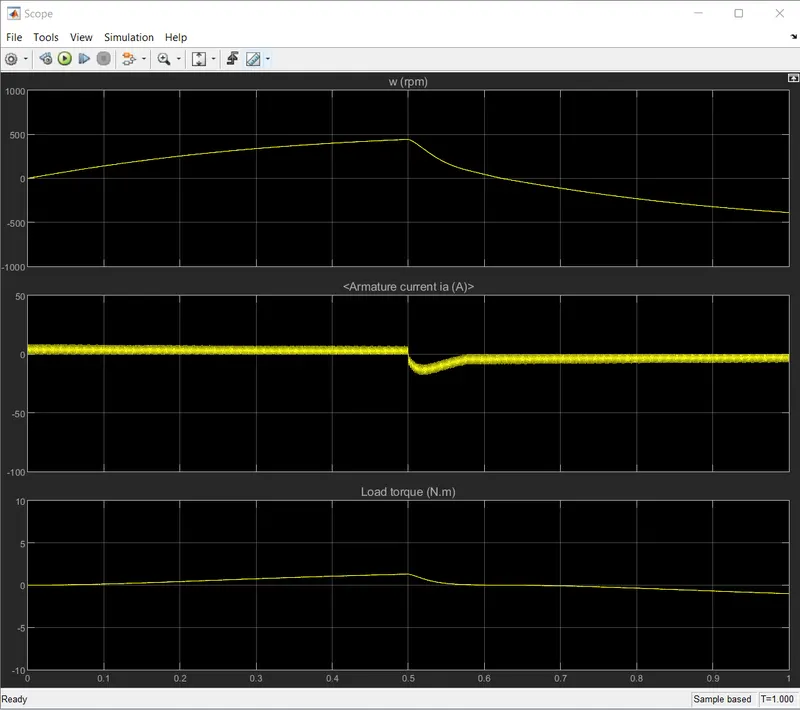
6. In this above scope, a flow of armature current is displayed and speed load torque is also displayed.
7. The change is made in pulse width as 50% from the pulse generator and results are shown that
voltage fluctuation is held in starting point of forwarding reverse state.
8. The sudden fluctuation is reduced in this experiment by reducing the pulse width of the input
supply.
9. A change is also held speed and load torque where the constant level of speed and torque is acted
in above scope compare with the previous 75% of the pulse width.
10. A time period of forwarding and reverse action is maintained as same as the previous duty cycle.
11. In this observation, the shoot up is reduced when motor changes direction from forward to reverse
compared to 75% of pulse width.
c] Refer to the help section of ‘The Four-Quadrant Chopper DC Drive (DC7) block’. Compare
it with the H-bridge model.
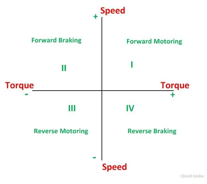
Four quadrant operation of any drives or DC motor means that the machine operates in four
quadrant. They are Forward Braking, Forward Motoring, Reverse Motoring and Reverse
Braking.
Model:
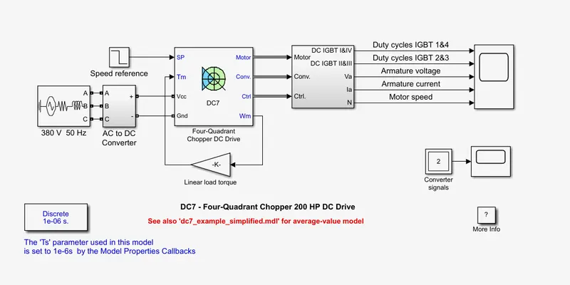
A four quadrant stage is the dedicated part of a power converters used to manage load voltage
and current in the four quadrant area. This function can be part of the converter topology
(thyristor-based or H-bridge DC-DC topologies) or as a kind of extensions to a standard
one-quadrant power converter.
The 200 HP DC motor is separately excited with a constant 150 V DC field voltage source.
The armature voltage is provided by an IGBT converter controlled by two PI regulators.
The converter is fed by a 515 V DC bus obtained by rectification of a 380 V AC 50 Hz voltage
source. In order to limit the DC bus voltage during dynamic braking mode, a braking chopper
has been added between the diode rectifier and the DC7 block.
The first regulator is a speed regulator, followed by a current regulator. The speed regulator
outputs the armature current references (in p.u.) used by the current controller in order to
obtain the electromagnetic torque needed to reach the desired speed. The speed references
change rate follows acceleration and deceleration ramps in order to avoid sudden reference
changes that could cause armature over-current and destabilize the system. The current
regulator controls the armature current by computing the appropriate duty ratios of the 5Hz
pulses of the four IGBT devices(pulse width modulationa). For proper system behaviour, the
instantaneous pulse values of IGBT devices 1 and 4 are opposite to those of IGBT devices 2
and 3 . This generates the average armature voltage needed to obtain the desired armature
currents. Inorder to limit the amplitude of the current oscillators, a smoothing inductance is
placed in series with the armature circuit.
DC chopper device has the advantages of high efficiency, flexibility in control, light
weight, small size, quick response and regeneration down to very low speed.
Result in Scope:-
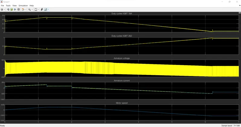
Comparison between The Four-Quadrant Chopper DC Drive (DC7) block and the H-bridge model.
4-Quadrant chopper H-bridge
1. In this model, speed reference input is used 1. In this model, the polarity is reversed across the terminal of the motor
to change the direction of motor rotation. w.r.t. the battery.
2. The speed reference values is changed to control 2. The speed of motor is controlled by varying with the pulse in pulse
the speed of the motor. generator.
3. DC drives operates in 4 modes. 3. DC drives operates in 2 modes.
4. PI controllers are used for speed and current 4. PI is absent BJT-H bridge.
control.
5. The disturbances and current shoot up is low. 5. The shoot up is high because of switching losses.
6. Overall performance and stability is good. 6. performance and stability is less compare with 4
quadrant chopper.
7. More complex system as it contain 4 switching 7. Less complex compare with 4 quadrant chopper.
devices.
Aim 2: Develop a 2-quadrant chopper using simulink & explain the working of the same with the
relevant results. (Refer to article - Multiquadrant operation of motor )
2- Quadrant chopper:
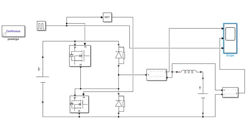
Simulink model of 2-Quadrant chopper:-
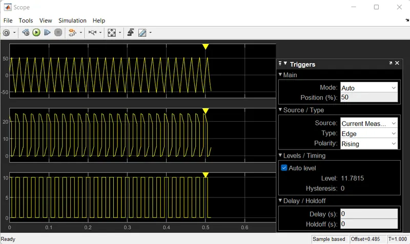
Output in scope:-
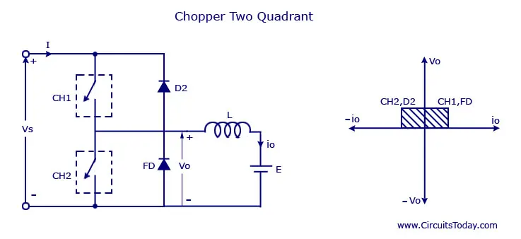
Two quadrant chopper is also called as type C-chopper. Type c chopper is obtained by connecting type
-A and type -B choppers are in parallel. We will always get a positive output voltage Vo as the free-
wheeling diode FD is present across the load. When the chopper is ON the freewheeling diode starts
conducting and the output voltage Vo will be equal to Vs. The direction of the load current io will be
reversed. The current io will be flowing towards the source and it will be positive regardless the
chopper is ON or the FD conducts. The load current will be negative if the chopper is or the diode
D2 conducts. We can say the chopper and FD operates together as a type -A chopper in first quadrant.
In the second quadrant, the chopper and D2 will operate together as type -B chopper.
The average output voltage will be always positive but the average load current might be positive
or negative. The power flow may be life the first quadrant i.e. from source to load or from load to
source like the second quadrant operation. The two chopper should not be turned ON simultaneously
as the combined action may cause a short circuit in supply lines. For regenerative braking and
motoring these type of chopper configuration is used.
In the simulation model various blocks are used:
1. pulse generator
2. mosfet
3. diode
4. logical operator(NOT)
5. scope
6. DC voltage source
7. Voltage measurement block
8. Current measurement block
9. RLC branch, etc.
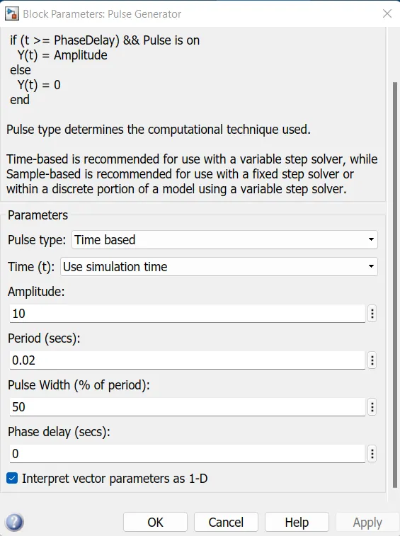
Block parameters of pulse generator is as shown below.
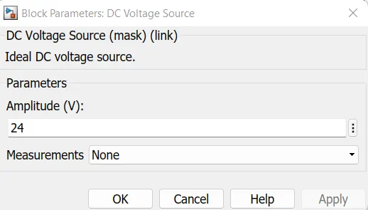
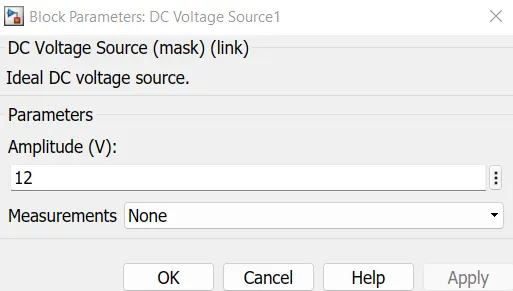
Block parametrs of voltage sources:
From the scope output, it can be seen that the voltage waveformis not going less
than Zero. The minimum value of voltage is zero and maximum value always in
the positive direction.
However, the current waveform is sometimes positive sometimes it is negative.
https://drive.google.com/file/d/1d1IF131JVdxLe6a0JHlED8NBSiouAXce/view?usp=sharing
Aim 3: Explain in a brief about operation of BLDC motor.
Working principle and operation of BLDC Motor:-
BLDC motor works on the principle similar to that of a conventional DC motor, i.e., the Lorentz
force law which states that whenever a current carrying conductor is placed in a magnetic field
it experiences a force. As a consequences of reaction forces, the magnet will experience an equal
and opposite force. In case BLDC motor, current carrying conductor is stationary while the
permanent magnet moves.
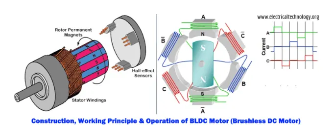
When the stator coils are electrically switched by a supply source. It becomes electromagnet
and starts producing the uniform field in the air gap. Though the source of supply is DC,
switching makes to generate an AC voltage waveform with trapezoidal shape. Due to force
of interaction between electromagnet stator and permanent magnet rotor, the rotor continue
to rotate.
consider the figure below in which motor stator is excited based on different switching states.
With the switching of windings as High and Low signals, corresponding winding energized as
North and South poles. The prmanent magnet rotor with North and South poles align with
stator poles causing motor to rotate.
observe that motor produces torque because of the development of attraction forces(when
North-South or South-North alignment) and repulsion forces (when North-North or South
-South alignment). By this way motor moves in a clockwise direction.
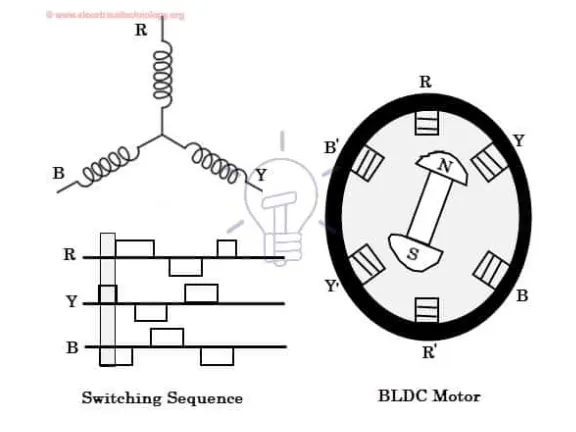
Here, one might get a question that how we know which stator coil should be energized and
when to do. This is because, the motor continuous rotation depends on the switching sequence
around the coils. As discussed abobe that Hall sensors give shaft position feedback to the
electronic controller unit.
Based on the signal from sensor, the controller decides particular coils to energize. Hall-effect
sensors generate. Low and High level signals whenever rotor poles pass near to it. These
signals determine the position of the shaft.
Advantages of BLDC Motor:-
1. It has no mechanical commutator and associated problems.
2. High efficiency due to use of permanent magnet rotor.
3. High speed of operation even in loaded and unloaded conditions due to the absence of
brushes that limits the speed.
4. Smaller motor geometry and lighter in weight than both brushed type DC and induction
AC motors.
5. Higher dynamic response due to low inertia and carrying windings in the stator.
6. Less electromagnetic intereference.
7. Quite operation(or less noise) due to absence of brushes.
Disadvantages of BLDC Motor:-
1. These motors are costly.
2. Electronic controllers are requiredcontrol this motor is expensive.
3. Not much availability of many integrated electronic control solutions, especially
for the tiny BLDC motors.
4. Requires complex drive circuitry.
5. Need of additional sensors.
Applications of BLDC Motors:-
BLDC are used for a variety of application requirements such as varying loads, constant
loads and positioning applications in the field of industrial control, automotive, aviation,
automation systems, health care equipments, etc.
Conclusions:
1. a) Speed control of a DC motor using BJT H-Bridge is studied.
b) Armature current shoot- up is studied from the scope result.
c) Comparison between 4-Quadrant chopper DC drive and H-bridge
is studied.
2. Simulink model of 2- Quadrant chopper is developed and output is
obtained in scope block.
3. Operation of BLDC motor is studied.