Project-1: Modelling an electric Car with Li-ion battery
Aim:
To Create a MATLAB model of an electric car in which we uses which uses lithium ion battery and suitable
motor choosing a suitable blocks from the Powertrain block set and Implement the Vehicle Speed by
using PI Controller and generate the accelerator and brake commands.
Objectives:
To prepare the technical report about the EV model including
1. System level configurations
2. Model parameters
3. Results
4. Conclusions
Theory:
An electric vehicles (EVs) use a battery pack to store the electrical energy that powers the motor.
EVs are sometimes referred to as battery electric vehicles (BEVs). EV batteries are charged by
plugging the vehicle into an electric power source.
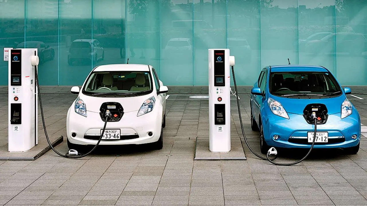
All-electric vehicles (EVs) have an electric motor instead of an internal combustion engine. The vehicle
uses a large traction battery pack to power the electric motor and must be plugged into a charging
station or wall outlet to charge. Because it runs on electricity, the vehicle emits no exhaust from a
tailpipe and does not contain the typical liquid fuel components, such as a fuel pump, fuel line, or fuel
tank.
All-electric vehicles (EVs) use a battery pack to store the electrical energy that powers the motor. EVs
are sometimes referred to as battery electric vehicles (BEVs). EV batteries are charged by plugging
the vehicle into an electric power source. Although electricity production may contribute to air
pollution, the U.S. Environmental Protection Agency categorizes all-electric vehicles as zero-emission
vehicles because they produce no direct exhaust or emissions.
Both heavy-duty and light-duty EVs are commercially available. EVs are typically more expensive than
similar conventional and hybrid vehicles, although some cost can be recovered through fuel savings, a
federal tax credit, or state incentives.
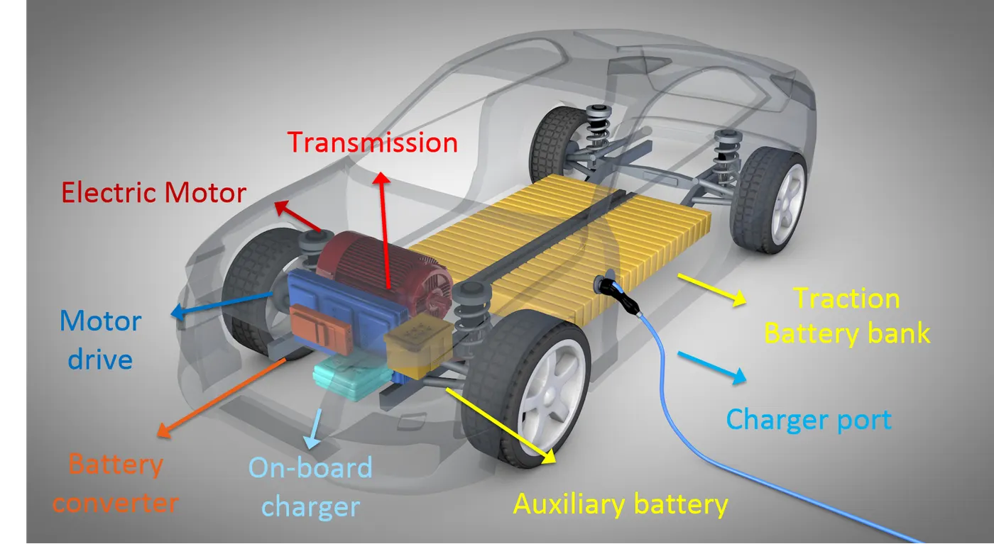
Components of an electric car:
1] Battery ( all-electric auxiliary):
In an electric drive vehicle, the auxiliary battery provides electricity to power vehicle accessories.
2] Charger port:
The charge port allows the vehicle to connect to an external power supply in order to charge the
traction battery pack.
3] DC/DC Converter:
This device converts higher-voltage DC power from the traction battery pack to the lower-voltage DC
power needed to run vehicle accessories and recharge the auxiliary battery.
4] Electric traction motor:
Using power from the traction battery pack, this motor drives the vehicle’s wheels. Some vehicles use
motor generators that perform both the drive and regeneration functions.
5] Onboard Charger:
Takes the incoming AC electricity supplied via the charge port and converts it to DC power for charging
the traction battery. It monitors battery characteristics such as voltage, current, temperature, and
state of charge while charging the pack.
6] Power electronic controller:
This unit manages the flow of electrical energy delivered by the traction battery, controlling the speed
of the electric traction motor and the torque it produces.
7] Thermal system (Cooling):
This system maintains a proper operating temperature range of the engine, electric motor, power
electronics, and other components.
8] Traction battery pack:
Stores electricity for use by the electric traction motor.
9] Transmission (electric):
The transmission transfers mechanical power from the electric traction motor to drive the wheels.
Driving Range
Today’s EVs generally have a shorter range (per charge) than comparable conventional vehicles have
(per tank of gas). The efficiency and driving range of EVs vary substantially based on driving
conditions. Extreme outside temperatures tend to reduce range because more energy must be used to
heat or cool the cabin. High driving speeds reduce range because of the energy required to overcome
increased drag. Compared with gradual acceleration, rapid acceleration reduces range. Hauling heavy
loads or driving up significant inclines also reduces range.
Advantages of an Electric vehicles:
1. Environment-friendly: Electric vehicles do not use fuels for combustion and hence there is no
emission or exhaust of gasses. Vehicles using fossil fuels are large contributors to harmful gas buildup
in the environment so the use of an electric car can help contribute to a cleaner atmosphere.
2. Renewable energy source: Electric vehicles run on electricity that is renewable whereas
conventional cars work on the burning of fossil fuels that exhaust the fossil-fuel reserves on earth.
3.Cost-effective: Electricity is much cheaper than fuels like petrol and diesel which suffer a frequent
price hike. The recharging of batteries is cost-effective if solar power is used at home.
4. Low maintenance: Electric vehicles have fewer moving parts so wear and tear is less as compared
to conventional auto parts. Repair work is also simple and less expensive relative to combustion
engines.
5. Less noise and smoother motion: Electric vehicles give a much smoother driving experience.
The absence of rapidly moving parts makes them much quiet with low sound generation.
6. Government support: Governments in various countries have offered tax credits as an incentive
to encourage people to use electric vehicles as a go-green initiative.
Disadvantages of an Electric vehicles:
1. High initial cost: Electric vehicles are still very expensive and many consumers consider them not
as affordable as conventional vehicles.
2. Charging station limitations: People who need to drive long distances are worried about getting
suitable charging stations midway which is not available everywhere.
3. Recharging takes time: Unlike conventional cars that require a few minutes for refilling fuel,
recharging of the electric vehicle takes much more time which is generally a few hours.
4. Limited choices: Presently there aren’t too many electric models of cars available to choose from
when it comes to the looks, designs, or customized versions.
5. Less driving range: The driving range of the electric vehicles is found to be less as compared to
conventional vehicles. Electric vehicles can be suitable for day-to-day travel but can be problematic for
a long-distance journey.
Model Parameters:
Vehicle Body subsystem:
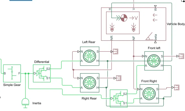
The Vehicle is assumed to be the front axle driven( 4 wheels and in 2 on each axle).
1] Tire
i] The Tire (Magic Formula) block models a tire with longitudinal behavior given by the Magic Formula,
an empirical equation based on four fitting coefficients. The block can model tire dynamics under
constant or variable pavement conditions.
ii] The longitudinal direction of the tire is the same as its direction of motion as it rolls on pavement.
iii] To increase the fidelity of the tire model, you can specify properties such as tire compliance, inertia,
and rolling resistance. However, these properties increase the complexity of the tire model and can
slow down simulation. Consider ignoring tire compliance and inertia if simulating the model in real
time or if preparing the model for hardware-in-the-loop (HIL) simulation.
The wheels are modelled using simple Tire( Magical formula) simulink blocks.
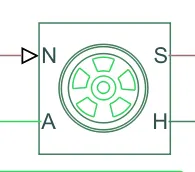
iv] The N port of the tire corresponds to the Normal Reaction acting on it.
v] The A port corresponds to the Mechanical Rotational Conserving Port for the four wheel axle.Thus
both the wheels on the same axle should form a connection through their respective A ports.
vi] Connection H corresponds to the Mechanical Translational Conserving Port for the Wheel hub
through which the thrust developed by the tire is applied to the vehicle.Thus, all the four wheels form
a connection through their respective H ports and thus in turn connected to the translationa; hub of
the vehicle body.
The connection S represent the output port for the slip of the tire.
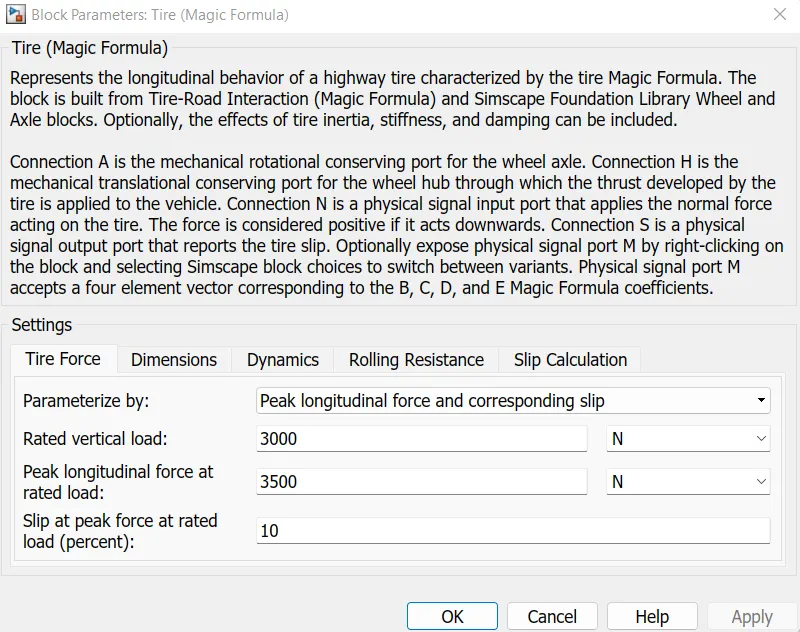
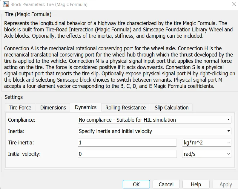
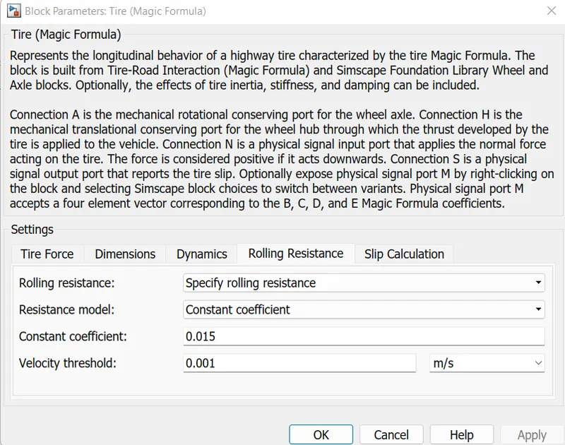
vii] The tires are parameterized by the peak longitudinal force and corresponding slip.
viii] The other block parameter such as rated vertical load, peak longitudinal force at rated load and
slip at peak force at rated load are kept with their default values.
ix] The tire radius is given as 0.3m.
x] The tire inertia is kept as 1 kg-m^2. Also the rolling resistance is given with a constant coefficient
of 0.015.
2] Vehicle body
This 2 axle (4 wheel) assembly is now connected to a velocity Body simscape block.
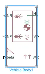
This block basically represent a two-axle vehicle body in longitudinal motion.The block accounts for
a] Body mass
b] Aerodynamic drag
c] Road incline
d] Weight distribution between axles due to acceleration
e] Road Profile.
Here the connection H is the mechanical translational conserving port NF and Nr are said to be a
normal reaction forces on the front axle and the rear wheels respectively.Connection V represent the
actual output translational velocity of the vehicle.
Beta is the road inclinational angle and W corresponds to the headwind speed (headwind-direction
opposite to that of the vehice)
The geometric paramerters of the vehicle body is given as;
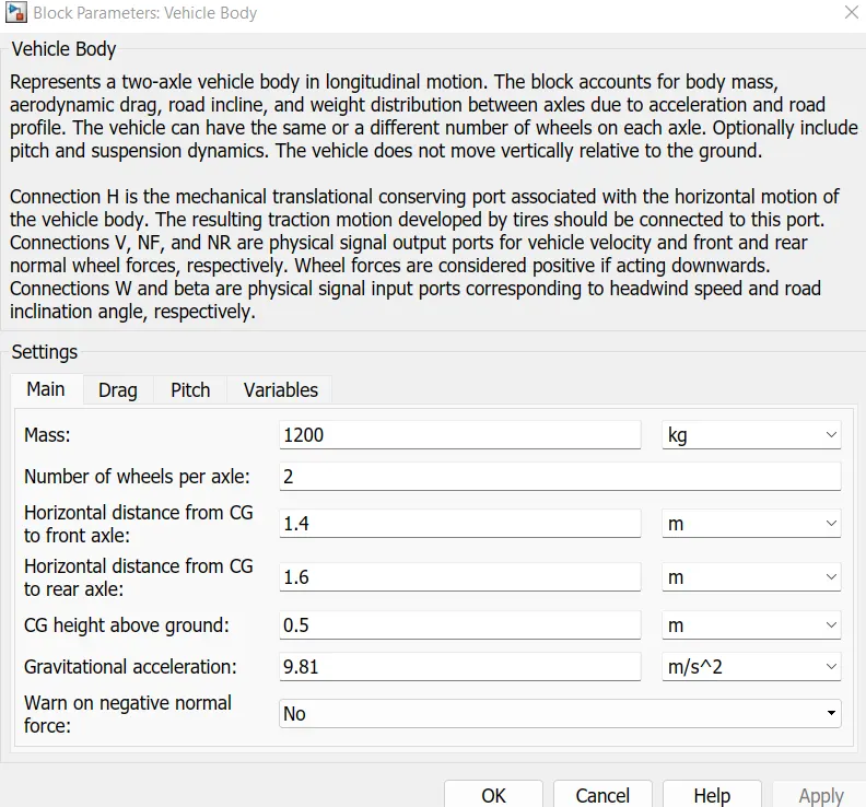
To be account for proper drag force on the vehicle, the related parameters are kept as follows,
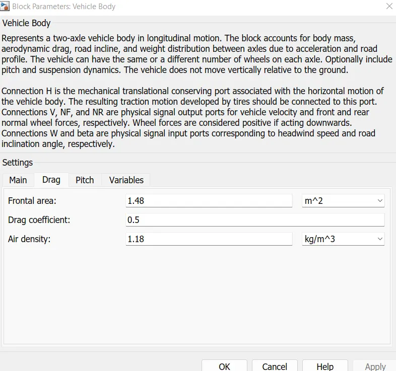
The pitch dynamics for the vehicle are not considered for this simulation.
3] Differential
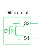
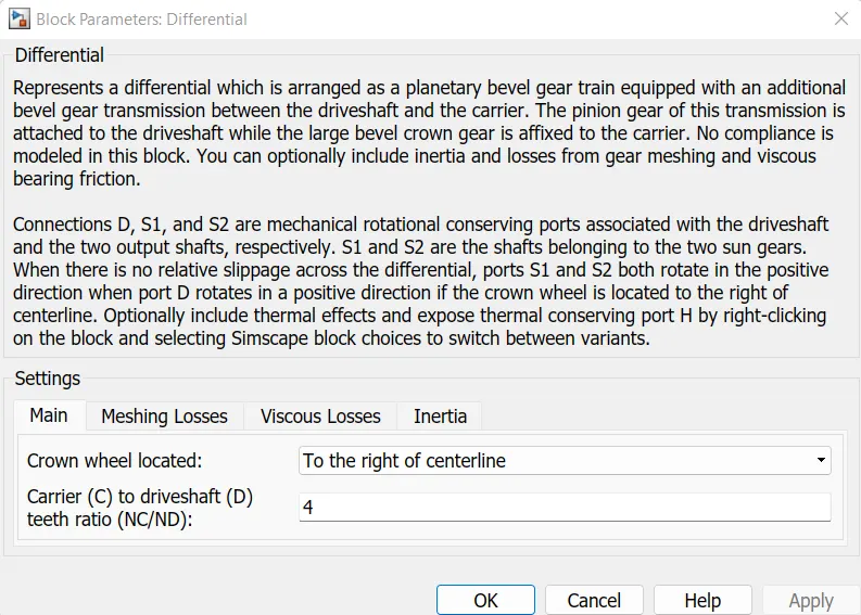
a] Gear mechanism that allows driven shafts to spin at different speeds.
b] The Differential block represents a gear mechanism that allows the driven shafts to spin at different
speeds. Differentials are common in automobiles, where they enable the various wheels to spin at
different speeds while cornering. Ports D, S1, and S2 represent the longitudinal driveshaft and the sun
gear shafts of the differential, respectively. Any one of the shafts can drive the other two.
4] Simple gear
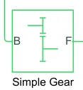
The Simple Gear block represents a gearbox that constrains the connected driveline axes of the base
gear, B, and the follower gear, F, to corotate with a fixed ratio that you specify. You choose whether the
follower axis rotates in the same or opposite direction as the base axis. If they rotate in the same
direction, the angular velocity of the follower, ωF, and the angular velocity of the base, ωB, have the
same sign. If they rotate in opposite directions, ωF and ωB have opposite signs.
The input for this subsystem is taken as the Rotational speed of the motor.
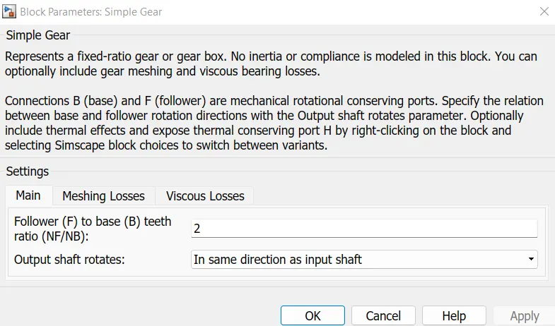
And here the rotational direction of the output shaft is kept as the same as the input shaft. Also, no
meshing losses are considered for the simulation.
5] Inertia
A concrete block which serves as a base for mechanical equipment such as fans or pumps; the block is
mounted on a resilient support to reduce the transmission of vibration to the EV structure.

Complete system of vehicle body is shown below,
DC Motor:
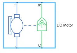
1. Simulink Provides an inbuilt model block for a DC motor which converts electrical input into
mechanical rotational output.
2. Note the blue colour corresponds to the electrical side of the motor and the green colour
corresponds to the mechanical side.
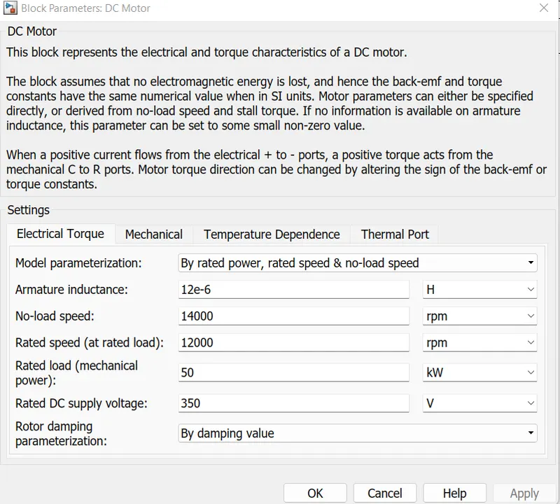
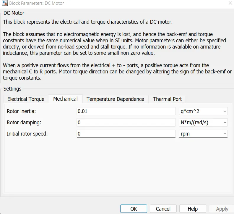
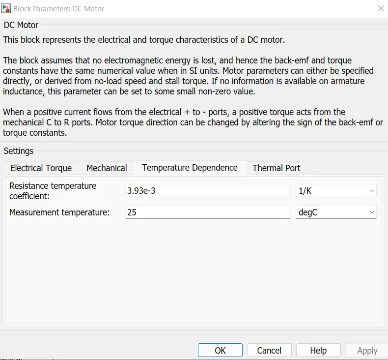
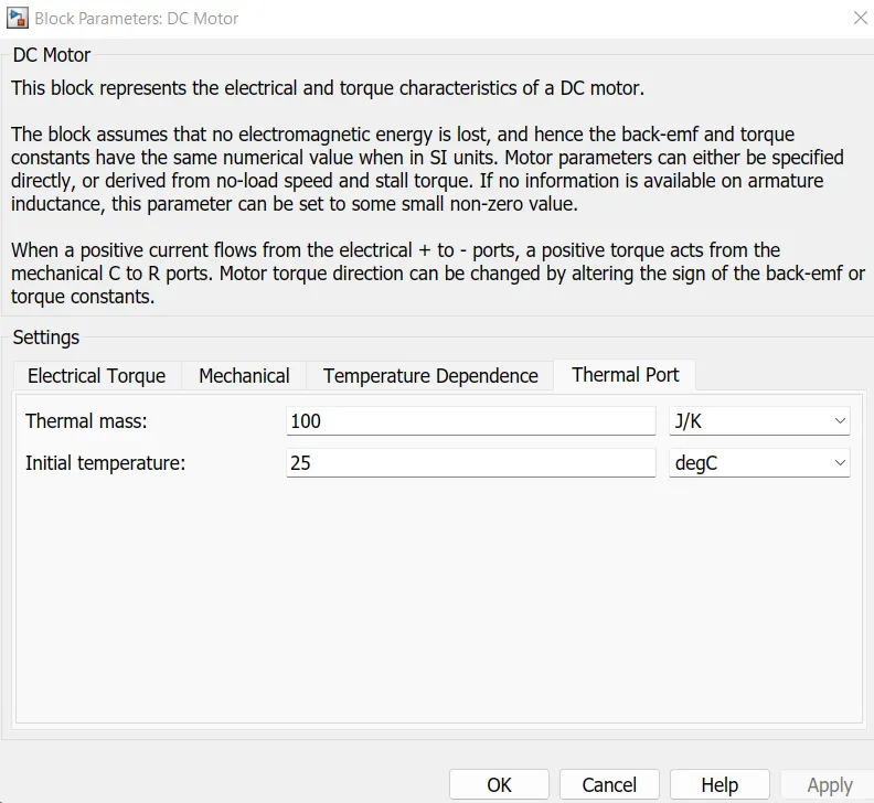
3. Here thr motor field type is kept as Permanent magnet and the model parameterization is done by
ratedd load and speed. The armature inductance and the mechanical parameters are given as their
default values.
All the other parameters are changed as shown below.
4. The connection R represent the Rotor while the connection C is for Casting (stationary). The C port
is connected to a mechanical rotational reference.
5. The + and - ve terminal of the motor are connected to the motor controller. If these terminals are
directly connected to a battery the required DC motor will run on the rated capacity of the battery.
This will eventually resulta into no control over the DC motor and the vehicle will run at the top speed
through out the simulation.
We consider the Inertia and the Friction and also the Temperature Sensor.
Motor Controller:
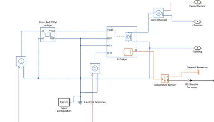
H-bridge circuit
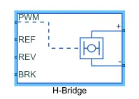
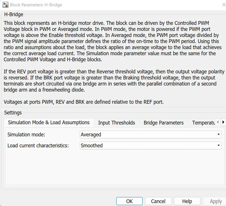
The H-Bridge block represents an H-bridge motor driver. The block has the following two Simulation
mode options:
1 PWM — The H-Bridge block output is a controlled voltage that depends on the input signal at
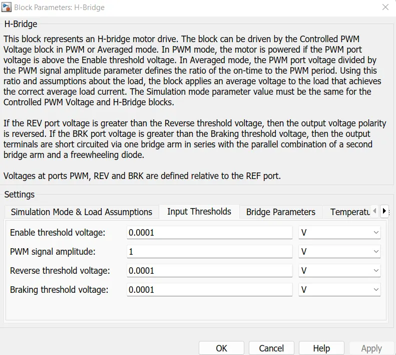
the PWM port. If the input signal has a value greater than the Enable threshold voltage parameter
value, the H-Bridge block output is on and has a value equal to the value of the Output voltage
amplitude parameter. If it has a value less than the Enable threshold voltage parameter value, the
block maintains the load circuit using one of the following three Freewheeling mode options:
1. Via 1 semiconductor switch and 1 freewheeling diode.
2. Via 2 freewheeling diodes.
3. Via 2 semiconductors switches and 1 freewheeling diode.
The first and third options are sometimes referred to as synchronous operation.
The signal at the REV port determines the polarity of the output. If the value of the signal at
the REV port is less than the value of the Reverse threshold voltage parameter, the output has positive
polarity; otherwise, it has negative polarity.
The block can be driven by the controlled PWM Voltage block in PWM or Averaged mode.
1. In PWM mode, the motor is powered if the PWM port voltage is above the enabled threshold
voltage.
2. In Averaged mode, the PWM port voltage divided by the PWM signal amplitudes parameter defines
that the ratio of on time yo the PWM period.
3. Connection REF is for the Reference input. This combined with the Pwm connected will form the
pulse input for the H Bridge.It is Electrical Reference.
4. Connection REV corresponds to the reverse motion of the motor which essentially means, the
backward motion of the vehicle. Here the backward motion of the vehicle is not accounted for and so
the port is connected to the electrical reference.
5. Connection BRK is for the braking the Vehicle.
6. The PWM mode results in a huge amount of simulation time. Averaged mode is selected for this
simulation.
7. Load current characteristics are considered to be smoothed here.
8. The regenerative braking is enabled for the simulation. This means when the vehicle starts
decelerating corresponding amount of charge will be fed back to the battery.
9. BRK input is connected to a controlled Voltage Source. This will generate emf corresponding to the
intensity of brakes applied and fed the power back to the battery.
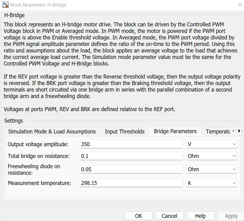
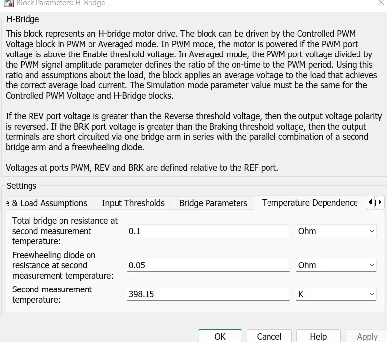
Output Voltage Amplitude of the H-Bridge circuit is given the same value as the rated DC supply
Voltage of the DC motor.
Controlled PWM Voltage block:
Simulink provides an inbuilt Controlled PWM Voltage block. This block is used for providing the proper
pulse input to the block.
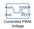
The Controlled PWM Voltage block represents a pulse-width modulated (PWM) voltage source.
1. Electrical input ports — The block calculates the duty cycle based on the reference voltage
across its ref+ and ref- ports. This modeling variant is the default.
2. PS input — Specify the duty cycle value directly by using an input physical signal port.
The PWM and REF connection are for the corresponding ports on the H-Bridge Circuit.The two
reference inputs corresponds to the throttle inputs given by the driver.The block generates
corresponding pulse width as per the acceleration and brakes applied by the driver himself.Here the
PWM frquency is 1000Hz. Also the simulation mode is Averaged as that in the H-Bridge circuit.
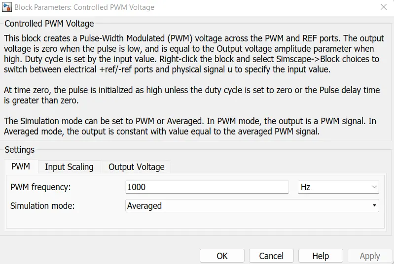
The input Scaling Parameters given as,
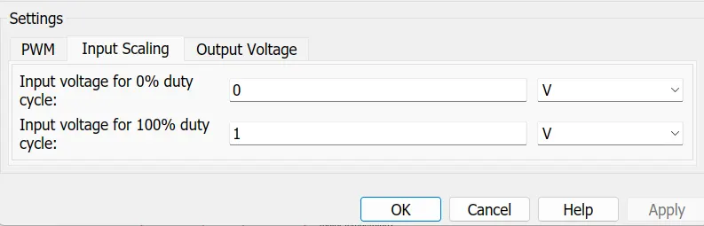
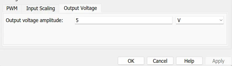
0V for 0% duty cycle and 5V for 100% duty cycle. So the output voltage amplitudes becomes 5V.
The H-Bridge circuit along with the PWM input, together form the motor controller circuit.
PID Controller:
The Discrete PID Controller block implements a PID controller (PID, PI, PD, P only, or I only). The
block is identical to PID Controller block with the Time domain parameter set to Discrete-time.
The block output is a weighted sum of the input signal, the integral of the input signal, and the
derivative of the input signal. The weights are the proportional, integral, and derivative gain
parameters. A first-order pole filters the derivative action.
The block supports several controller types and structures. Configurable options in the block include:
-
Controller type (PID, PI, PD, P only, or I only)
-
Controller form (Parallel or Ideal)
-
Time domain (continuous or discrete)
-
Initial conditions and reset trigger
-
Output saturation limits and built-in anti-windup mechanism
-
Signal tracking for bumpless control transfer and multiloop control
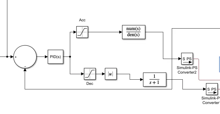
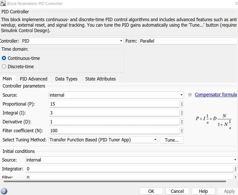
The output from the sum block is given to this block based on the PID, the output is generated.
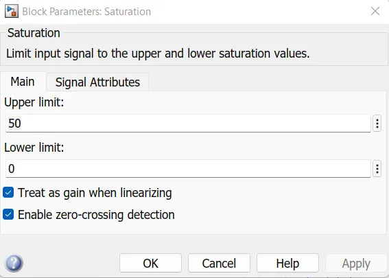
The Saturation block produces an output signal that is the value of the input signal bounded to the
upper and lower saturation values. The upper and lower limits are specified by the parameters Upper
limit and Lower limit.
Input Output
Lower limit <= upper limit Input value
Input value < Upper limit Lower limit
Input value > upper limit Upper limit
In the Saturation there is two types they are,
Acceleration:
Deceleration:
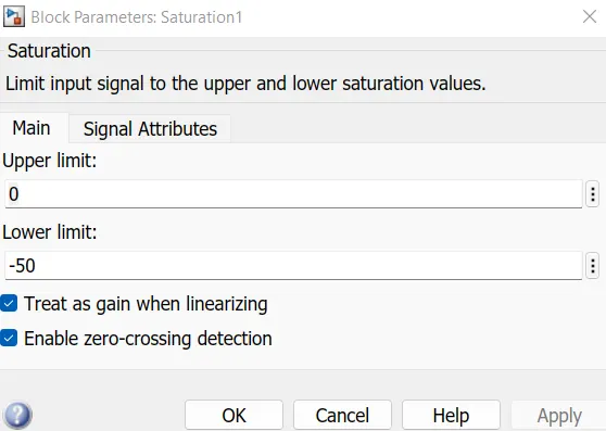
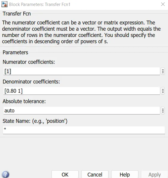
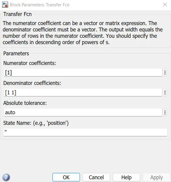
This blocks helps to limit the output signal from the PID controller and the separate deceleration and
the acceleration values.
The output from these block is sent to a transfer function then these are provided to the motor
Controller block.
Battery:
A lithium-ion (Li-ion) battery is an advanced battery technology that uses lithium ions as a key
component of its electrochemistry. During a discharge cycle, lithium atoms in the anode are ionized
and separated from their electrons. The lithium ions move from the anode and pass through the
electrolyte until they reach the cathode, where they recombine with their electrons and electrically
neutralize. The lithium ions are small enough to be able to move through a micro-permeable separator
between the anode and cathode. In part because of lithium’s small size (third only to hydrogen and
helium), Li-ion batteries are capable of having a very high voltage and charge storage per unit mass
and unit volume.
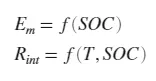
To calculate the voltage, the block implements these equations.
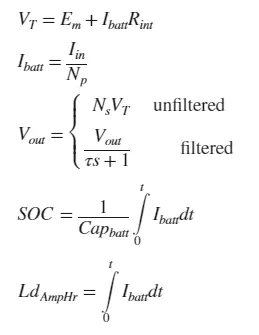
Positive current indicates battery discharge. Negative current indicates battery charge.
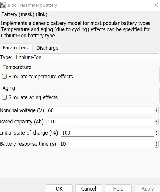
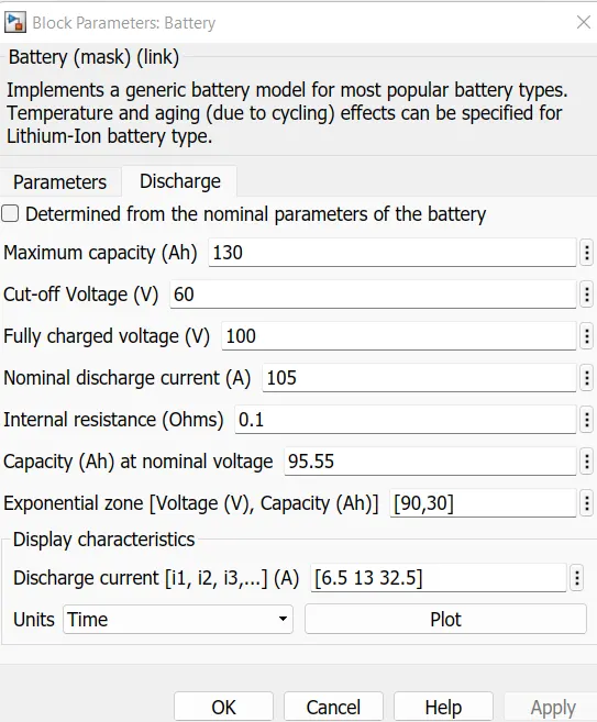
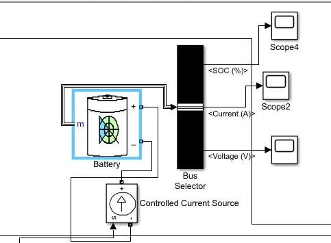
Complete model of the Lithium ion battery;
Temperature Sensor block:
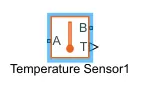
The Temperature Sensor block represents an ideal temperature sensor, that is, a device that
determines the temperature differential measured between two points without drawing any heat.
Connections A and B are thermal conserving ports that connect to the two points where temperature is
being monitored. Port T is a physical signal port that outputs the temperature differential value.
The block positive direction is from port A to port B. The measured temperature is determined as
T = TA – TB.
The block has the following ports:
A- Thermal conserving port associated with the sensor +ve probe.
B- Thermal conserving port associated with the sensor -ve probe.
C- Physical signal output port for temperature.
References:
1] Electrical Reference: Used to ground the all the electrical connections.
2] Mechanical Rotational Reference: Used to ground the all mechanical rotational ports.
3] Thermal Reference: Used to ground the thermal sensor.
Solver configuration:
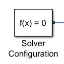
It is used to defines the solver settings to use for simulations.
System Level Configuration:
Drive cycle source ( Reference Velocity):
1. The Drive cycle source block is used to provide the reference speed for the simulation.
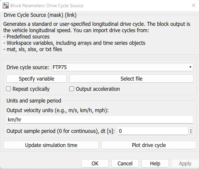
2. It generates is a standard or user-specified longitudinal drive cycle.
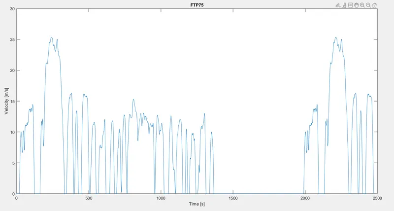
A] For 1st drive cycle source;
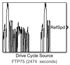
Here, the selected drive cycle is the standard FTP75.
The plot of drive cycle source is shown below.
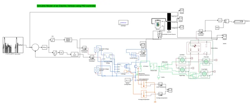
Simulink Model Of an electric vehicle using PID controller:
Result :
A]
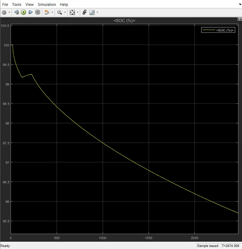
Upto 200 sec battery is discharge to 99.1 from 100 %. Then after regeneration takes place for next
100 sec After that battery gradually discharged to 95.58% for the complete simulation time.
B]
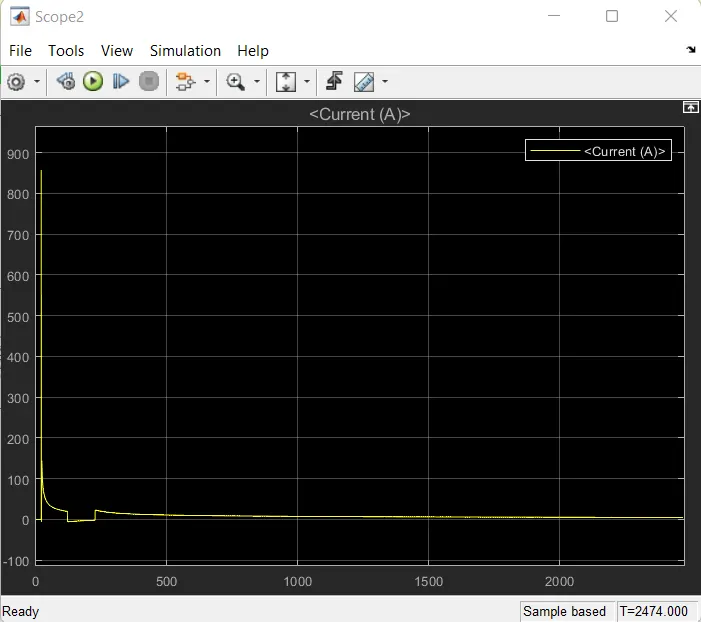
Initially current shoot up to above 800 Amp for 1st 100 sec time. After time of 2000 sec it becomes
nearly equal to zero.
C]
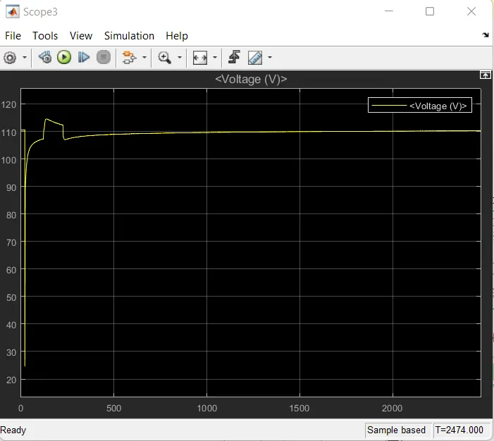
From 110 to 25v voltage gets reduced. Again voltage reaches to 100v attaining some peak it settles to
108v for the rest of the cycle
D] 1. The run time is kept at 2474 seconds because the total run time of the FTP drive cycle is
2474seconds.
2. Now we will see the actual drive cycle and the reference cycle.
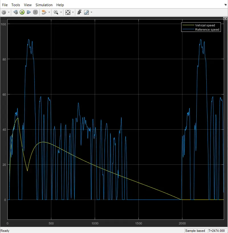
3. From the plot it is evident that the actual drive cycle is almost trying to following the the reference
drive cycle.
4. But the peak velocity is lesser in the actual drive cycle(46 km/hr). This is because of many factors,
The rolling resistance of the vehicle is taken into the consideration and hence this will affect the
velocity of the vehicle.
5. The wind velocity also affect the speed of the Vehicle.
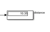
From this drive cycle the Vehicle can able to cover the distance of 10.35 km/hr.
E]
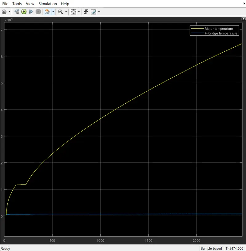
The motor perform based on the drive cycle when the drive cycle reference velocity increased motor
speed keep on increasing when it reduce the motor speed keep on reduced but it does not match
exactly with drive cycle because the motor operation when the drive cycle is reduced fastely the motor
cannot able to reduce that much fast because the braking operation needs some time.
The motor temperature is increased from 0 to 6.2 within 2474 we need to provide coolant in this
system so that motor perform better and controller temperature is maintained some what constant in
this system.
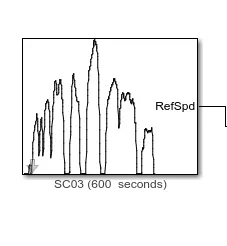
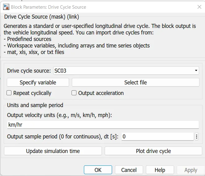
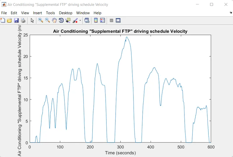
B] For 2nd Drive cycle source;
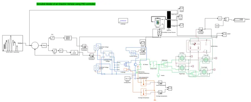
Simulink Model Of an electric vehicle using PID controller:
Results:
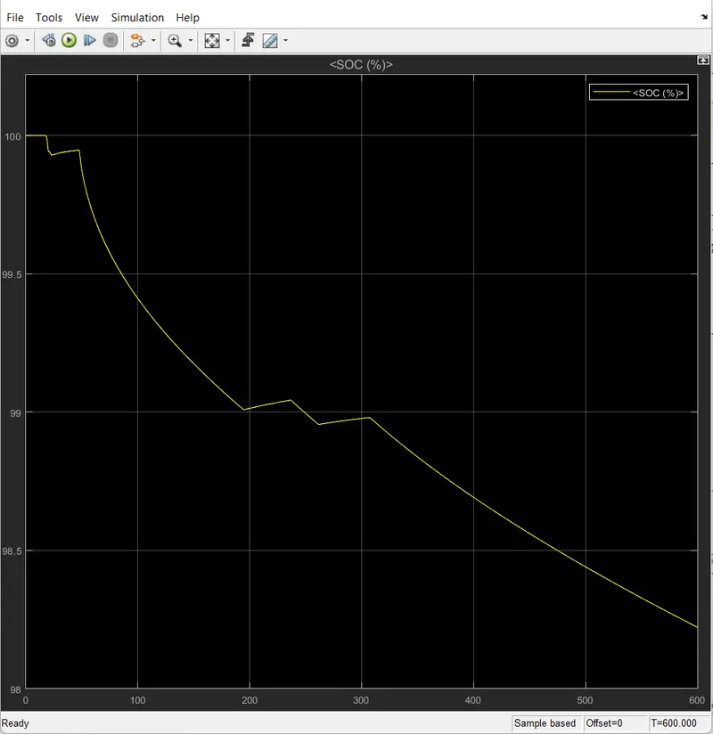
A] During this simulation battery discharged to 98.3%.
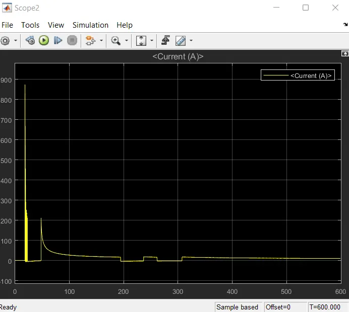
B] Behaviour of current is nearly equal to previous drive cycle source. Settling time is different here.
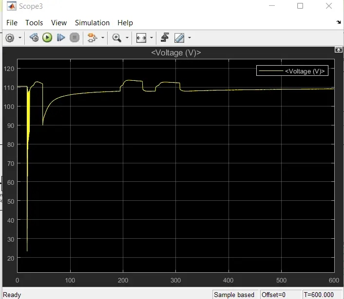
C]
The voltage is comes to 90v for first 50 sec. Then it try to attain its maximum range of 1.9-110v.
D]
1. The run time is kept at 600 seconds because the total run time of the SC03drive cycle is
2474seconds.
2. Now we will see the actual drive cycle and the reference cycle.
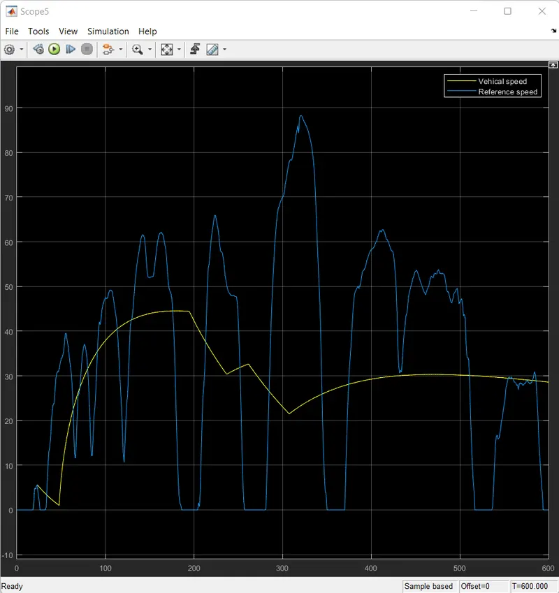
3. From the plot it is evident that the actual drive cycle is almost trying to following the the reference
drive cycle.
4. But the peak velocity is lesser in the actual drive cycle. This is because of many factors,
The rolling resistance of the vehicle is taken into the consideration and hence this will affect the
velocity of the vehicle.
5. The wind velocity also affect the speed of the Vehicle.
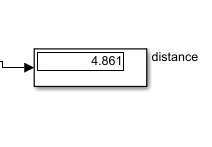
From this drive cycle the Vehicle can able to cover the distance of 4.861 km/hr.
E]
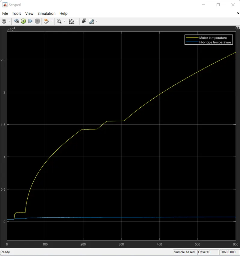
The motor perform based on the drive cycle when the drive cycle reference velocity increased motor
speed keep on increasing when it reduce the motor speed keep on reduced but it does not match
exactly with drive cycle because the motor operation when the drive cycle is reduced fastely the
motor cannot able to reduce that much fast because the braking operation performed here from
it takes atleast some time so that we cannot match exactly with the drive cycle.
The motor temperature is increased from 0.1 to 2.5 within 430 sec we need to provide coolant in this
system so that motor perform better and controller temperature is maintained some what constant in
this system.
https://drive.google.com/file/d/19teUeIRbVLmI9yE8kwskUmFos2C41mjg/view?usp=sharing
Kindly open this attached link with simulink(MATLAB).
Conclusions:
I have Created a MATLAB model of an electric car which uses lithium ion battery with suitable motor
and by using suitable blocks from the Simscape or Powertrain Block set , I have Implemented the
vehicle speed control using PI Controller and generate a brake and accelerator commands, perform
the System level Configuration, Model Parameters and the model run as per the reference input
give with less error in it due to PID Controller.