Week 8 - Simulating Cyclone separator with Discrete Phase Modelling
Aim:- To perform analysis on cyclone separator and calculate the separation efficiency and pressure drop.
Objective:-
- To write a few words about any four empirical models used to calculate the cyclone separator efficiency.
- To perform an analysis on a given cyclone separator model by varying the particle diameter from 1 μm to 5 μm and calculate the separation efficiency in each case. Discuss the results. [Use both the velocity's as 3m/sec.]
- To perform an analysis on a given cyclone separator model by varying the particle velocity from 1 m/sec to 5 m/sec and calculate the separation efficiency and pressure drop in each case. Discuss the results. [Use particle diameter size as 5 μm for all cases & keep flow velocity same as particle velocity]
Boundary Conditions:-
Inlet and wall:- Reflect
Outlet(Top):- Escape
Outlet(Bottom/dustbin) - Trap
Note:
Structural mesh gives the best results, so you can use cutcell meshing approach available in Ansys Meshing.
Introduction of Cyclone Separator with its Application:
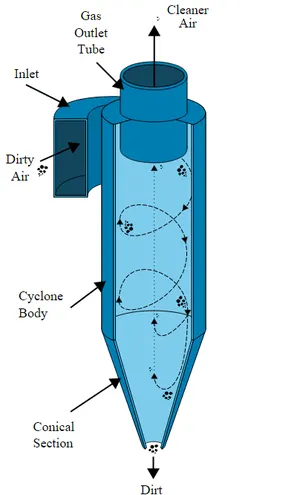
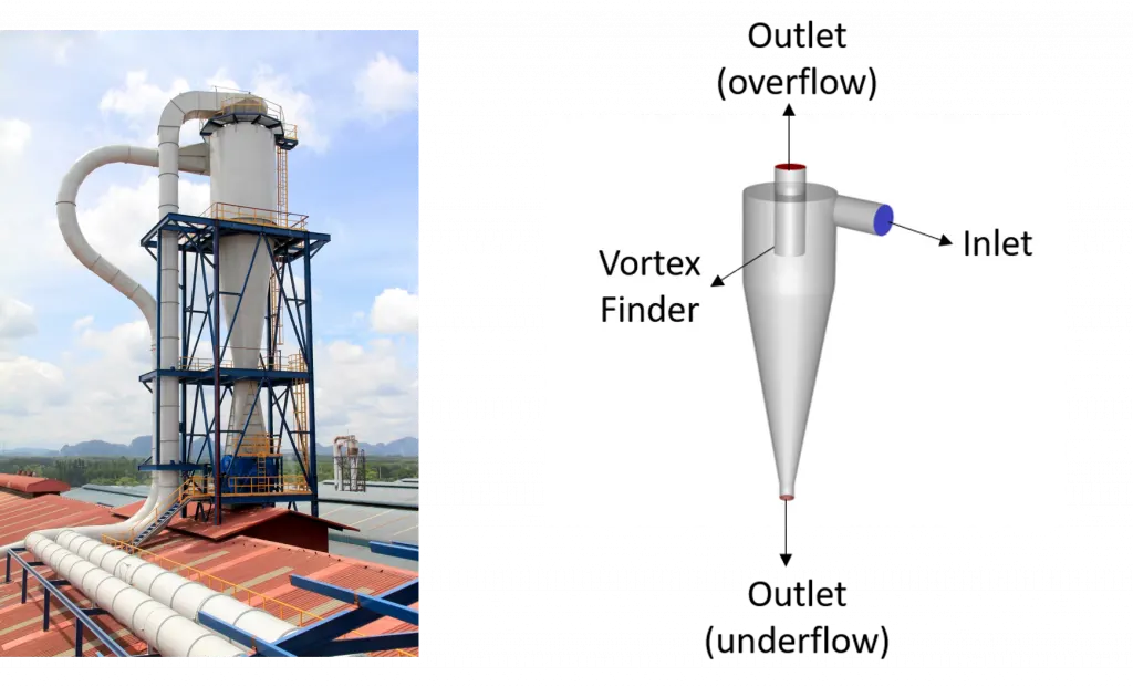
Cyclonic separation is a widely used separation technique in the process, oil and gas, and cement industries. The mechanism of separation occurring within the cyclone is known as classification, whereby fine and coarse, as well as lighter and heavier particles, are separated according to their terminal velocity in the fluid. The cyclone works by inducing spiral rotation in the primary phase, which imposes an enhanced radial acceleration on suspended particulates due to the centrifugal force. Conventional cylindrical cyclone devices consist of a conically shaped vessel, two outlets (underflow and overflow), both on the axis of symmetry, and a feed inlet connected to a cylindrical section. The underflow is situated at the apex of the cone. The overflow is an inner tube which passes through the top of the cyclone. The portion of the overflow pipe that extends into the body of the cyclone is a short, removable section known as the vortex finder. The vortex finder prevents short-circuiting of the feed directly into the overflow.
Due to the imposed swirl, larger particles migrate radially to the outer wall and then spiral down to the underflow. Smaller particles migrate more slowly and are captured in an upward spiral in the center of the cyclone and leave through the top via the vortex finder. Liquid cyclones, commonly known as hydrocyclones, are open to the atmosphere, which adds additional complexity. Due to the low pressure at the cyclone axis, a backflow of gas can occur, forming a gas core. Experimental work has shown that in the central core region under the vortex finder, the tangential velocity increases sharply with increasing radial distance; outside the central core, the tangential velocity decreases with increasing radius.
Cyclones are devices that employ a centrifugal force generated by a spinning gas stream to separate particles from the carrier gas. Their simple design, low capital cost, and nearly maintenance-free operation make them ideal for use as pre-cleaners for more expensive final control devices such as baghouses or electrostatic precipitators. Cyclones are particularly well suited for high temperature and pressure conditions because of their rugged design and flexible component materials. Cyclone collection efficiencies can reach 99% for particles bigger than 5 μm, and can be operated at very high dust loading. Cyclones are used for the removal of large particles for both air pollution control and process use. Application in extreme conditions includes the removal of coal dust in a power plant and the use as a spray dryer or gasification reactor. Engineers are generally interested in two parameters in order to carry out an assessment of the design and performance of a cyclone. These parameters are the collection efficiency of particle and pressure drop through the cyclone. An accurate prediction of cyclone efficiency is very important because inaccuracy in the efficiency prediction may result in an inefficient design of the cyclone separator. CFD has a great potential to predict the flow field characteristics and particle trajectories inside the cyclone as well as the pressure drop. The complicated swirling turbulent flow in a cyclone places great demands on the numerical techniques and the turbulence models employed in the CFD codes when modeling the cyclone pressure drop.
Collection efficiency
The collection or separation efficiency is most properly defined for a given particle size. As mentioned, fractional efficiency is defined as the fraction of particles of a given size collected in the cyclone, compared to those of that size going into the cyclone. Experience shows that collection efficiency of cyclone separator increases with increasing particle mean diameter and density; increasing gas tangential velocity; decreasing cyclone diameter; increasing cyclone length; extraction of gas along with solids through the cyclone legs. Several equations have been developed to predict the collection efficiency in cyclones through correlation equations. The following section describes two methods of calculating cyclone efficiency. First the theory proposed by Leith and Licht for calculating fractional efficiency will be discussed and then a convenient graphical method developed by Lappel will be presented. The fractional efficiency equation of Leith and Licht is given as:
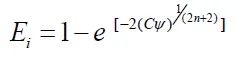
Where C = cyclone dimension factor; ψ = impaction parameter; n = vortex exponent
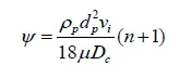
In this expression, c is a factor that is a function only of the cyclone’s dimensions. The symbol ψ expresses characteristics of the particles and gas and is known as inertia or impaction parameter. The value of n is dependent on the cyclone diameter and temperature of the gas stream. And ρp times vi expresses the particle’s initial momentum.
Pressure drop
alternatively, it can be thought of as the amount of resistance the cyclone separator adds to the system flow. The pressure drop is a product of the gas flow rate, gas density and cyclone geometry. Pressure drop can be expressed as:
DR = Ra Inlet – Ra Outlet
Where:
DR = Cyclone Pressure Drop
Ra = Absolute Pressure
Factors affecting Cyclone Separator's Efficiency are:
There are several factors that can affect a cyclone separator's efficiency. These include particle density, particle size, volumetric flow rate, pressure drop, cone length, body length, a ratio of accept port to body diameter, and even the smoothness of the cyclone’s internal surfaces.
Four empirical models used to calculate the cyclone separator efficiency.
1)Iozia and Leith Model:
Iozia and Leith logistic model is a modified version of Barth Model, which is developed based on force balance. The model assumes that a particle carried by the vortex endures the influence of two forces: a centrifugal force, Z and a flow resistance, W. The collection efficiency E of particle diameter dpi can be calculated from
E =1/(1 + (dpc/dpi )^beta)
2)Li and Wang Model:
The Li and Wang model include particle bounce or re-entrainment and turbulent diffusion at the cyclone wall. A two-dimensional analytical expression of particle distribution in the cyclone is obtained.
The resultant expression of the collection efficiency for particle of any size is given as
E = 1 − exp{−lambda*theta(1)}
where
theta1 = (2*pie(S + L))/a
3) Koch and Licht Model:
Koch and Licht collection theory recognized the inherently turbulent nature of cyclones and the distribution of gas residence times within the cyclone. Koch and Licht described particle motion in the entry and collection regions with the additional following assumptions:
- The tangential velocity of a particle is equal to the tangential velocity of the gas flow, i.e. there is no slip in the tangential direction between the particle and the gas.
- The tangential velocity is related to the radius of cyclone by uRn = constant.
A force balance and an equation on the particles collection yields
the grade efficiency E
E = 1 – exp*{-2*[((G*tau*Q)/(D^3))*(n+1)]^0.5/(n+1)}
4) Lapple Model:
Lapple model was developed based on force balance without considering the flow resistance. Lapple assumed that a particle entering the cyclone is evenly distributed across the inlet opening. The particle that travels from inlet half width to the wall in the cyclone is collected with 50% efficiency.
The efficiency of collection of any size of particle is given by
E =1/(1 + (dpc/dpi )^2)
Where, dpi is particle diameter and dpc is cut diameter.
Discrete Phase Modelling(DPM):
DPM is employed when we want to represent solid particles and gas or liquid or say liquid droplets in a gas or sometimes bubble in a liquid. So, PDM consists of two phases, one is called Continuous phase and another is called the Discrete phase. The continuous phase consists of fluid that is flowing within the fluid volume and the discrete phase consists of smaller particles that are supposed to be interacting with the continuous phase. The Discrete phase can also exchange momentum, mass, and energy with the fluid phase or continuous phase in this case.
> GEOMETRY:
extract the volume.
Prepare > volume extract > select edges > click on ok.
> MESHING:
Perform the structured mesh with element size of 5mm having cartesian method.
> PRE PROCESSING:
case 1.1:
The velocity of the particle and gas as 3m/s and the size of the particle diameter as 5micrometer.
| SOLVER TYPE | PRESSURE BASED |
| SOLVER TIME | STEADY STATE |
| ENERGY | OFF |
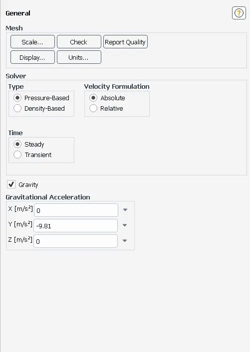
| GRAVITY | ON ( Y AXIS - -9.81m/s^2) |
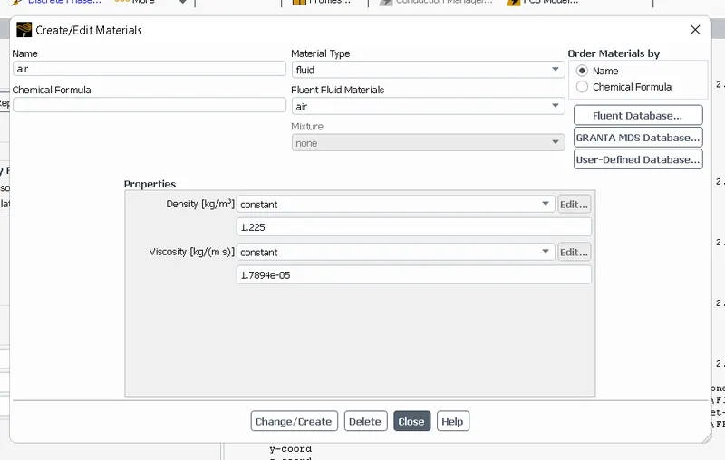
| MATERIAL | AIR |
| METHOD | COUPLED |
| DPM | ENABLED+CONTINIOUS PHASE+INJECTIONS+SURFACE+MATERIAL TYPE ANTHRACITE |
| X-VELOCITY 3m/s | |
| Diameter 5*10^-6 | |
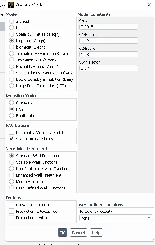
| VISCOUS MODEL | K-EPSILON+RNG+SWIRL DOMINATED FLOW+STANDARD WALL FUNCTIONS |
> Perform general settings as solver type as Pressure based, solver time as steady state, enable gravity.
> USE K-EPSILON+ RNG +SWIRL DOMINATED FLOW+STANDARD WALL FUNCTIONS, So This model is slight modification of the standard K-epsilon model which enhances the accuracy for the sirling flows.
the standard k–ε turbulence model is inadequate to simulate flows with swirl because it leads to excessive turbulence viscosities and unrealistic tangential velocities.
> use material as air.
> For particle flow in the dilute flow are anthracite.
> use boundary conditions.
| BOUNDARIES | TYPE | DPM |
| INLET | VELOCITY INLET WITH V=3m/s | reflect |
| outlet top | pessure outlet with atmospheric conditions | escape |
| outlet bottom | pressure outlet with atmospheric conditions | trapped |
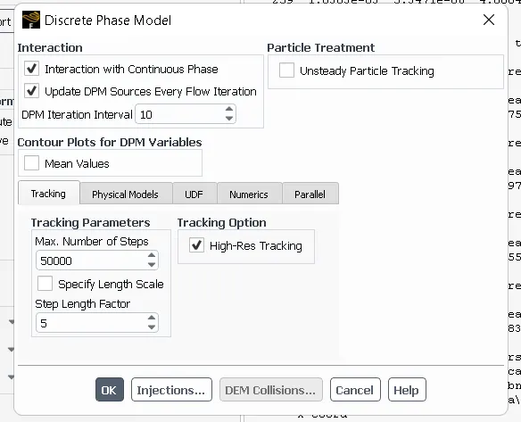
To enable the interaction between gas and solid particles, Turn on DPM
Click on Interaction with Continuous Phase to enable the couple flow (interaction between gas and solid particles).
Select Update DPM sources every flow iterations- to calculate particle source term at every iterations.
Select Contour plots for DPM variables – to allow cell average variable value which is use for Post processing.
Tracking parameter- select maximum number of steps 50,000 and Step length factor 5 - the larger the step length factor the smaller will be the time step(dt).
Now to specify the injection of the discrete particles on to the Continous phase,
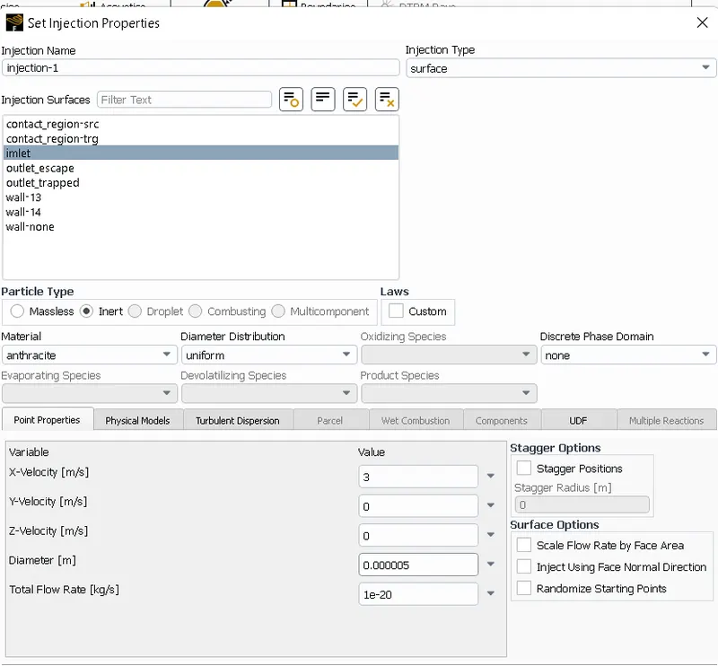
Select Injections->create->particle type->inert->Material(Anthracite)->Injection type(surface injections)->Surface release(inlet).
Point properties: x-velocity-3m/s, Diameter – 5microns, Total flow rate- 1e-20 kg/s.
Solution:
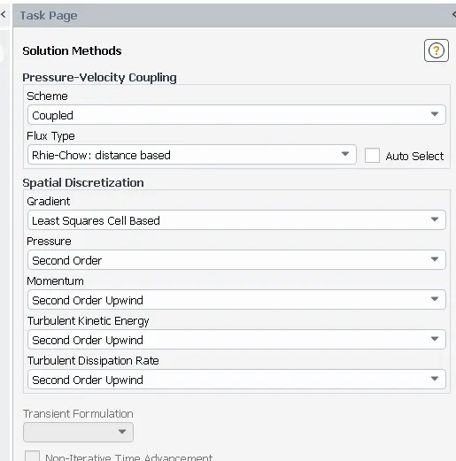
Methods
For Turbulent Kinetic Energy-> 2nd order Upwind Interpolation scheme as it is unconditionally stable.
For Turbulent Dissipation rate-> 2nd order Upwind Interpolation scheme as it is unconditionally stable.
Control: Pressure of particle 0.1 , momentum of particles 0.3.
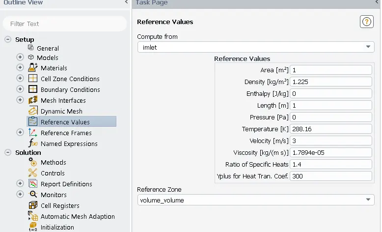
Solving: Standard Initialization->options->compute from inlet->Initialize and calculate.
After calculations, check DPM data from console and Export-> Particle History data from injection1 folder for CFD Post
> RESULTS:
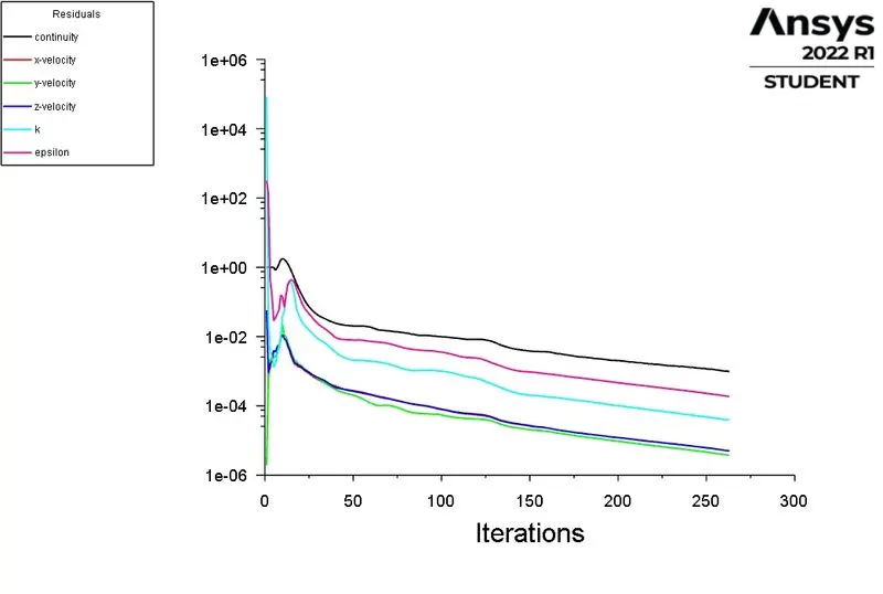
> SCALED RESIDUALS:
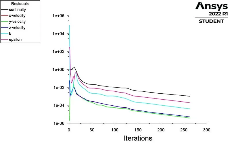
The solution is converged after 263 iterations.
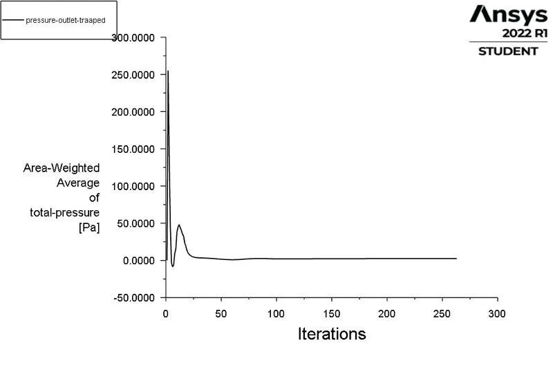
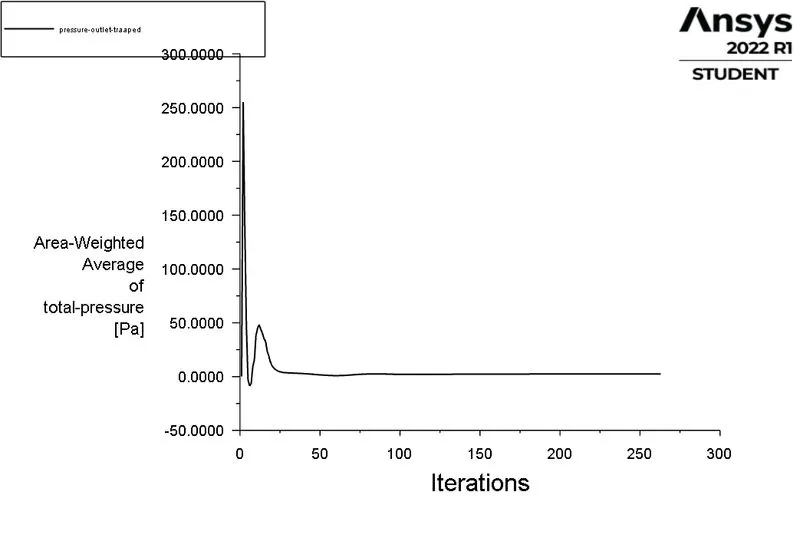
> PRESSURE AT OUTLET TRAPPED.
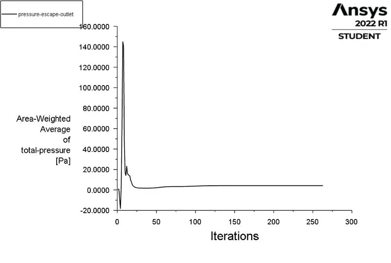
> PRESSURE AT OUTLET ESCAPE:
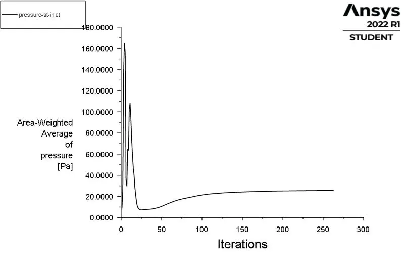
> PRESSURE AT INLET:
> Number tracked = 378
number escaped = 104
number trapped = 248
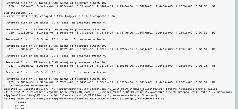
The separation efficiency is defined as the ratio of the particle traaped at the bottom to the total number of tracked elements.It is the measurement of the cyclone separator ability to separate the particles from the flowing gas stream.
cyclone separator efficiecncy = 65.60%
> Cut poinys are the point at which particles are removed from the gas stream at 50% efficiency.
> The pressure values at diffrent locations.
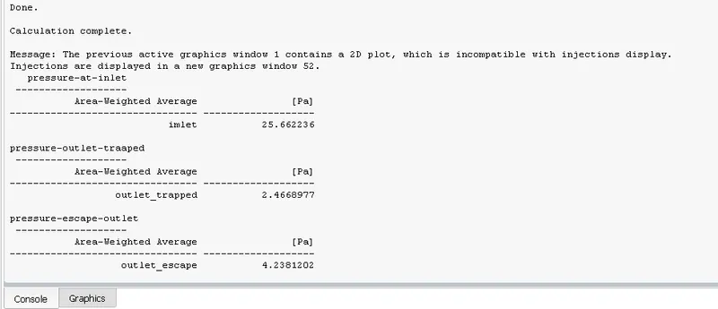
Pressure at inlet = 25.662
pressure at outlet trapped = 2.466
Pressure diffrence between pressure at inlet to the pressure at outlet trap = 19.63
POST PROCESSING:
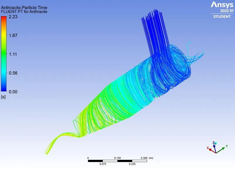
Anthracite particle time plot:
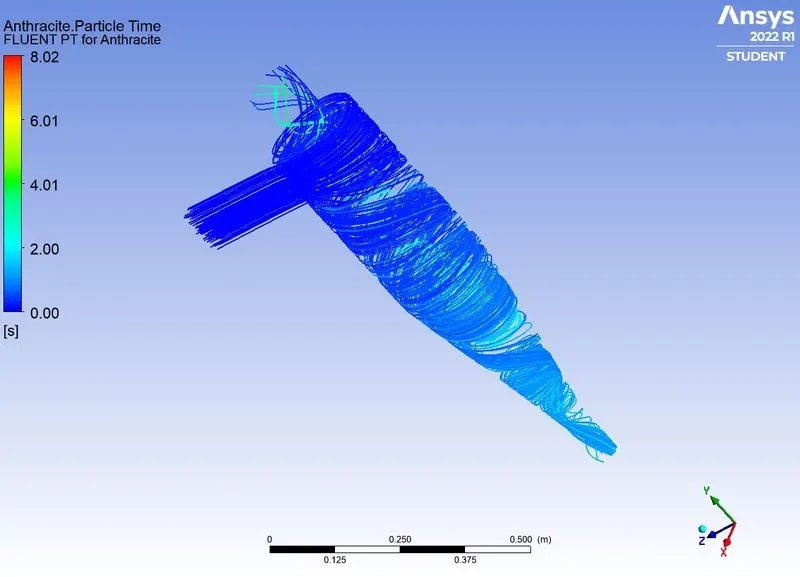
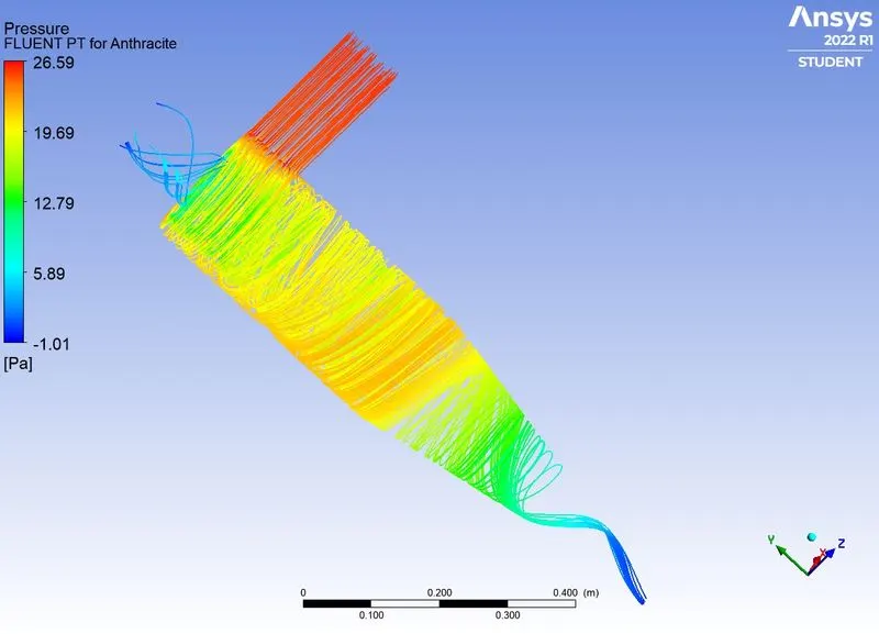
> pressure contour:
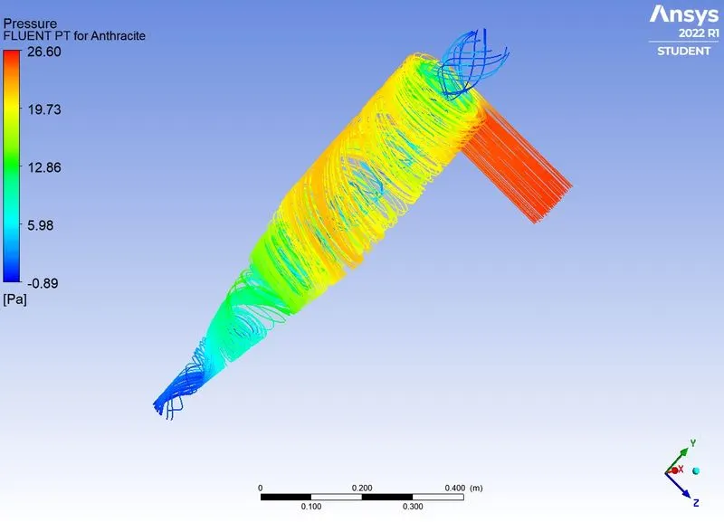
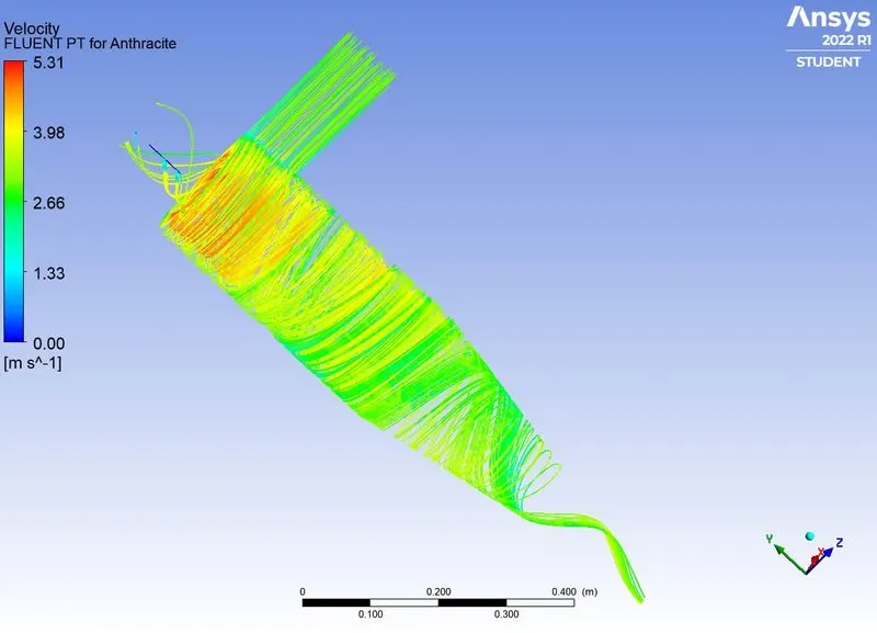
> Velocity contour:
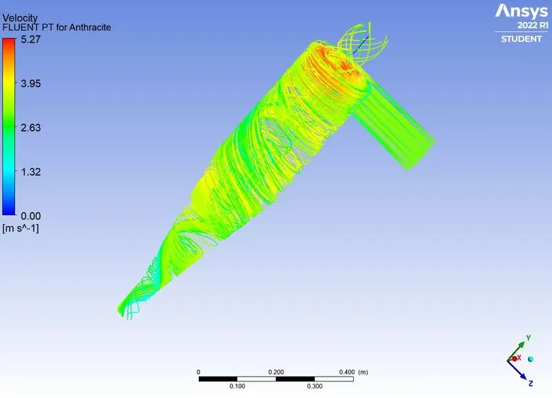
Case 1.2:
The velocity of gas and anthracite as 3m/s and size of Anthracite particle as 1micrometer.
> Scaled residuals:
> pressure at inlet :
> pressure at outlet trapped:
> pressure at outlet escape:
POST- PROCESSING:
> Anthracite particle time plot:
> Pressure contour:
> velocity contour:
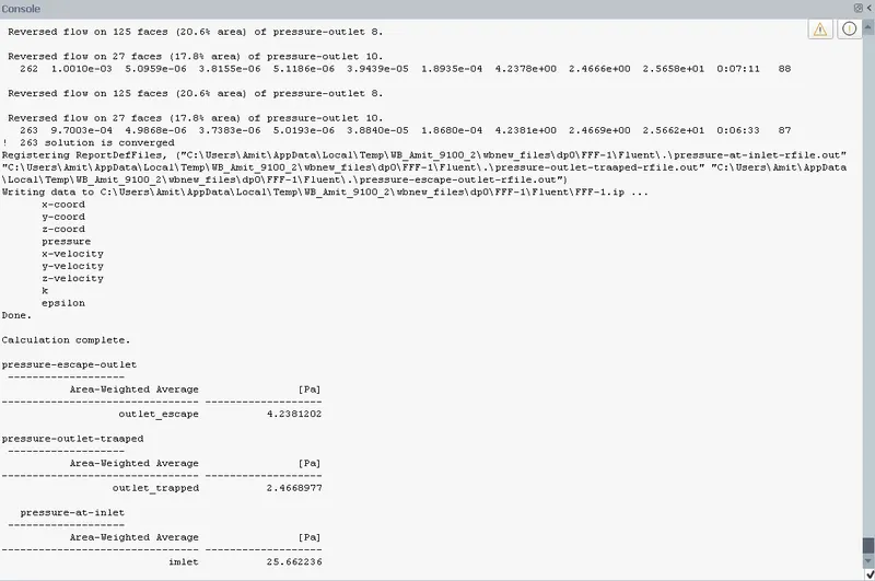
The solution is converged after 263 iterations.
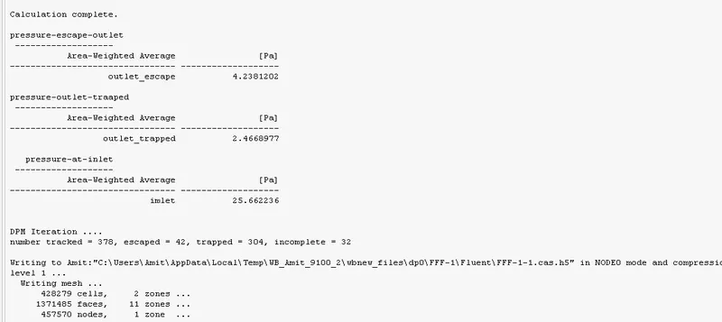
Paticle tracked at inlet = 378
partcle trapped at outlet trap = 304
The cyclone separator efficiency = 80.423%
Pressure at inlet = 25.66
Pressure at outlet trapped = 2.466
Pressure diffrence between inlet and outlet trapped = 23.1963
case 1.3:
The velocity of gas and anthracite particle are 3m/s and size of Anthracite particle are 3 micrometer.
> Scaled residuals:
> Pressure at inlet:
> pressure at outlet escaped:
> pressure at outlet tarpped:
The soultion is converged after after 212 iterations.
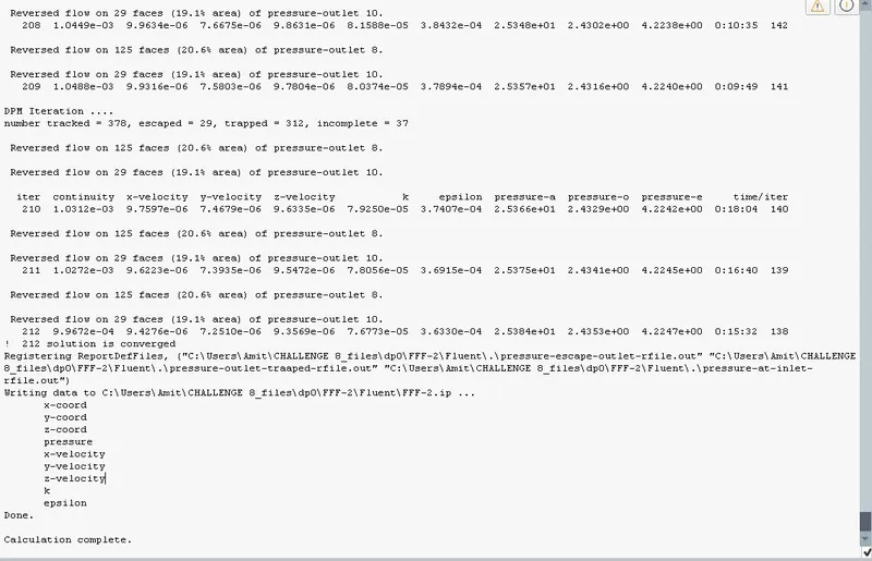
Total number of partcle tracked at inlet = 378
Total number of particle trapped at outlet = 312
separator efficiency = 82.539%
Post Processing:
> Anthracite particle time plot:
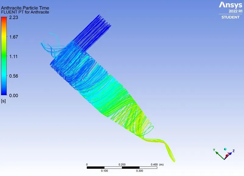
> velocity contour:
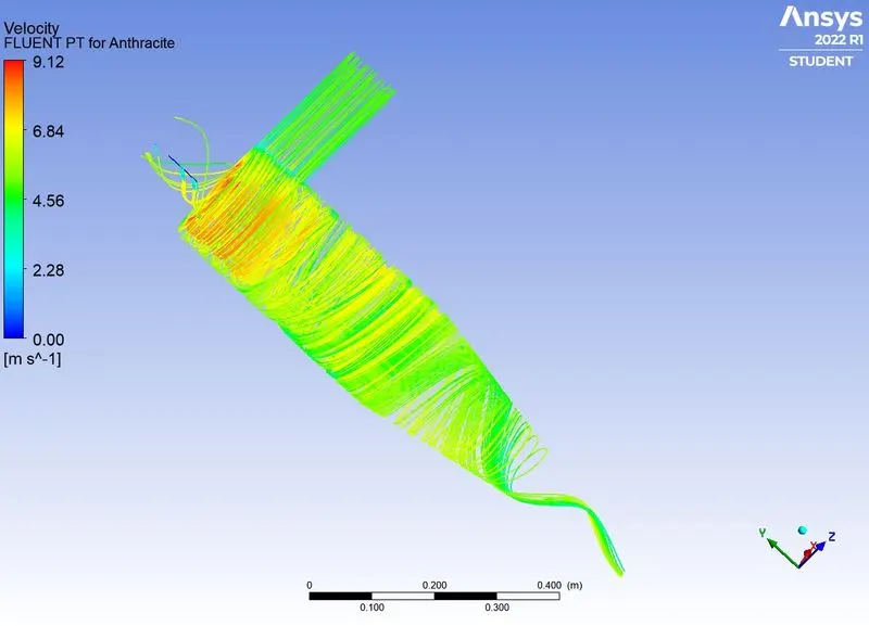
> pressure contour
| CASES | velocity of particle and gas | diameter of particle | pressure diffrence | separation efficiency | anthracite particle time |
| Case1 | 3 m/s | 0.000001 | 23.1963 | 80.423% | 2.23s |
| CASE 2 | 3 m/s | 0.000003 | 23.1963 | 82.539% | 2.23 |
| CASE 3 | 3 m/s | 0.000005 | 23.1963 | 65.29% | 8.02s |
Case 1.4:
Velocity of the gas and anthracite particle are 5m/s and size of anthracite particle are 3 micrometer.
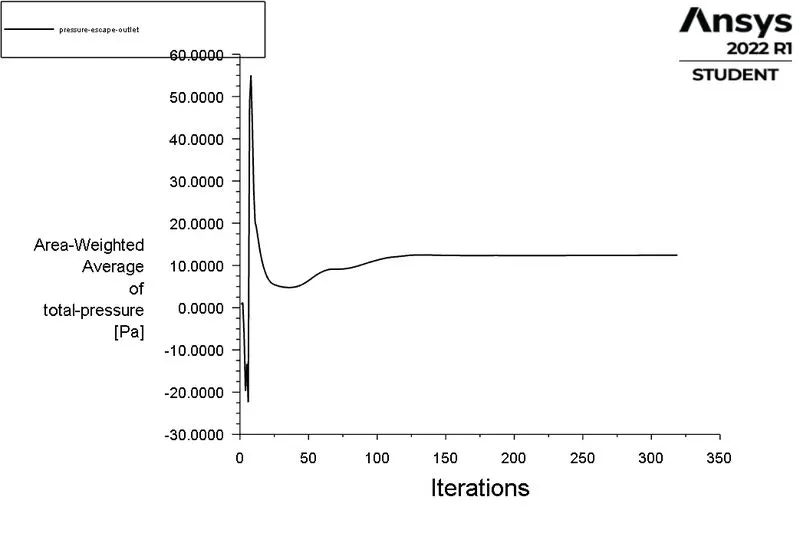
> Scaled residuals:
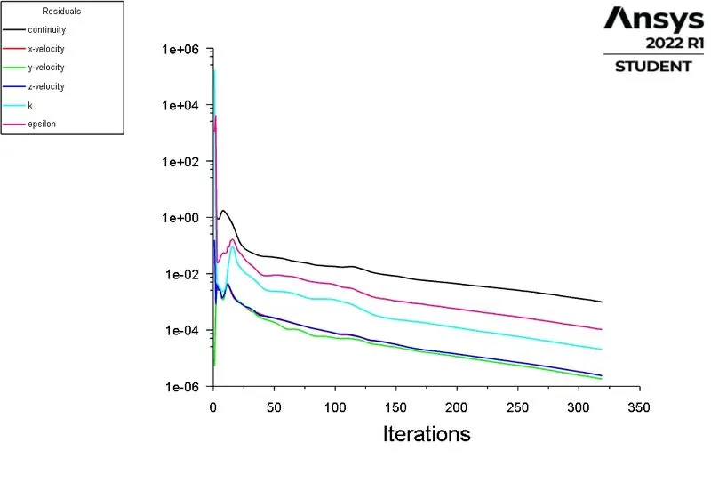
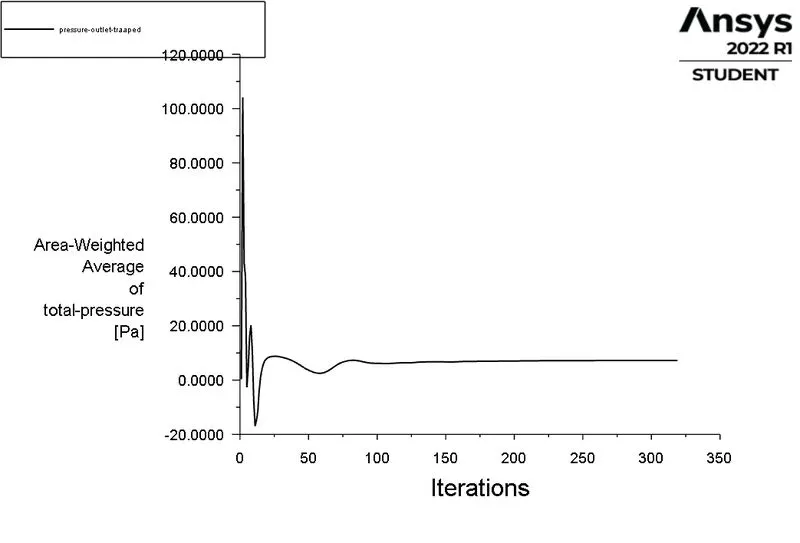
The solution is converged after 320 iterations.
> Pressure at outlet escape:
> Pressure at outlet trapped:
> Pressure at inlet:
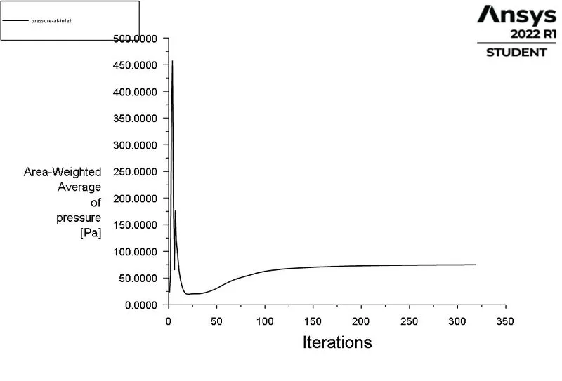
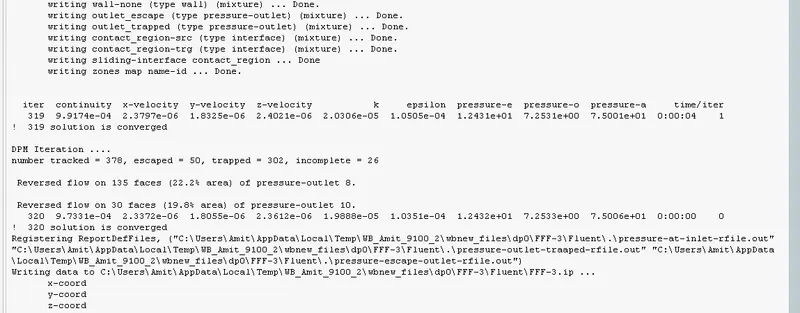
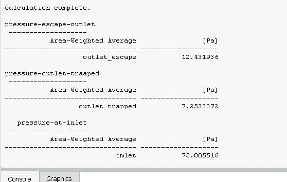
Total pressure at inlet = 75
Toal pressure at outlet trapped = 7.25
Total pressure diffrence between inlet and outlet trapped = 67.75
Number of particle tracked at inlet = 378
Number of particle trapped at outlet = 302
separation efficiency = 79.89%
Post processing:
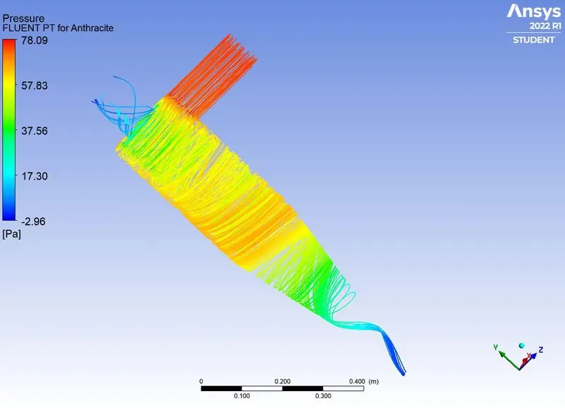
> Anthracite particle time plot:
> Pressure contour:
> velocity contour:
RESULTS:
| CASES | VELOCITY OF GAS AND PARTICLE | DIAMETER OF PARTICLE | PRESSURE DIFFRENCE | ANTHRACITE PARTICLE TIME | SEPARATOR EFFICIENCY |
| CASE 3 | 3 m/s | 0.000003m | 23.1963 | 9.12 | 79.89% |
| CASE 4 | 5 m/s | 0.000003m | 67.75 | 9.12 | 82.25% |
Conclusion:
- As the velocity(tangential velocity) of gas and particles increases for the same size of the particle, the Efficiency of Cyclone separator and Pressure drop also increases due to inertia.
- As the particle size increases the Efficiency of Cyclone separator and Pressure drop also increases.