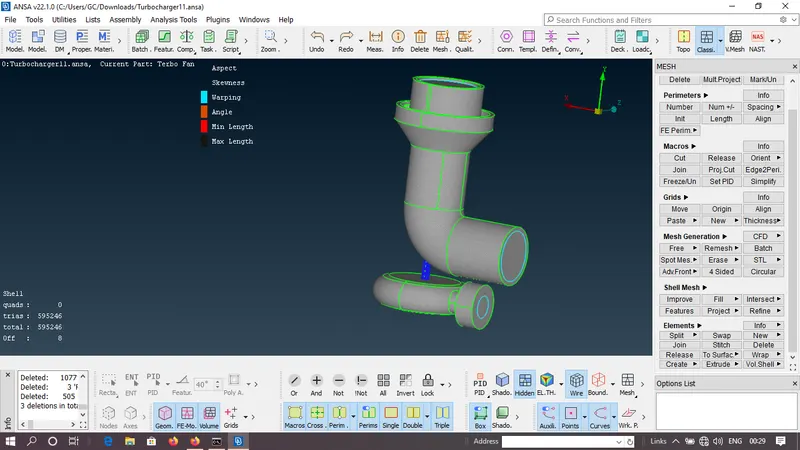
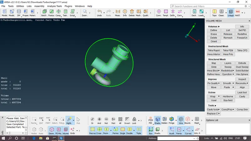
Week 3 Challenge : CFD meshing on Turbocharger
AIM : CFD MESHING ON TURBOCHARGER.
PROBLEM STATEMENT:
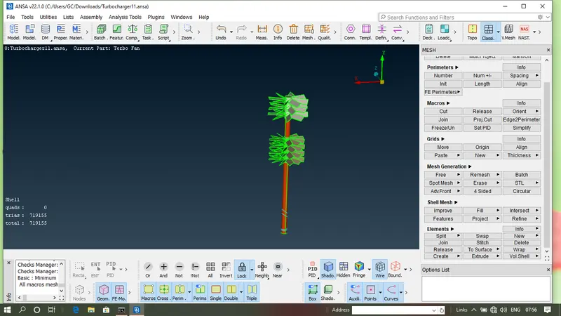
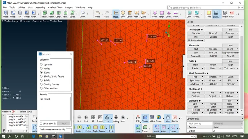
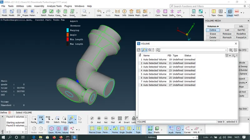
For the given model, check for the geometrical errors to make appropriate volumes. Create and assign PIDs as shown in the video. Perform surface mesh with the given target lengths as per PIDs.
- Blade stage-1 = 1 mm
- Blade stage-2 = 1 mm
- Impeller = 2 mm
- Shaft rotor = 1 mm
- Turbo casing = 5 mm
- Compressor casing = 5 mm
- Inlet casing cover = 5 mm
PROCEDURE:
Open the turbocharger ansa file on ANSA software.
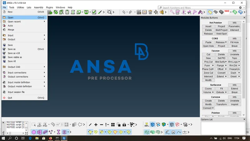
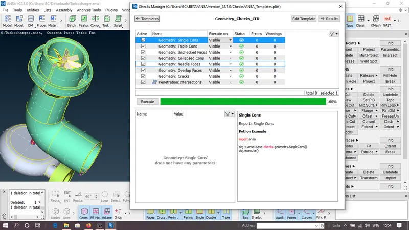
Perform topological geometrical cleanup such as elimination of single cons,tripple cons,penetrating and overlapping surfaces,small open surfaces, cracks, etc.
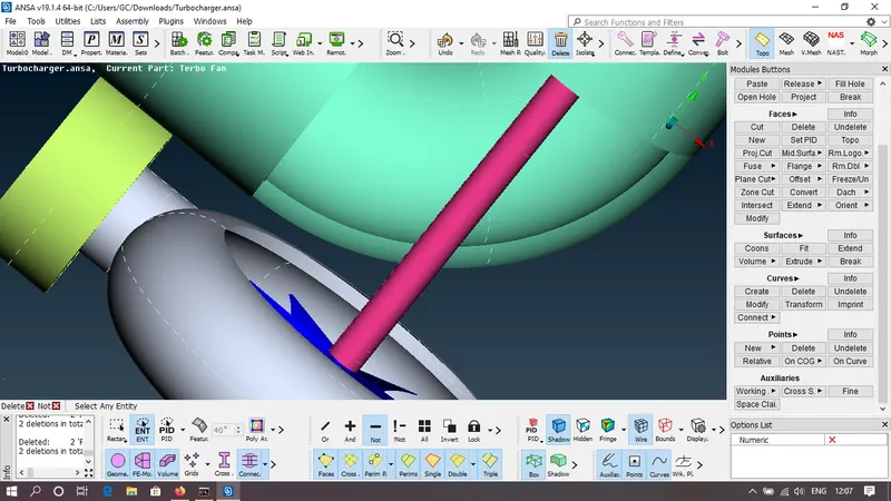
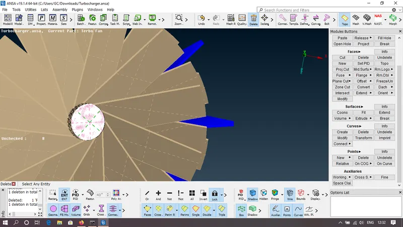
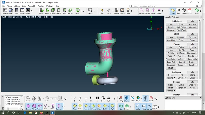
To perform topological geometric cleanup first start with the elimination of overlapping surfaces. overlapping surfaces are the surfaces where two surfaces are ovelapped to each other.
as shown in image.
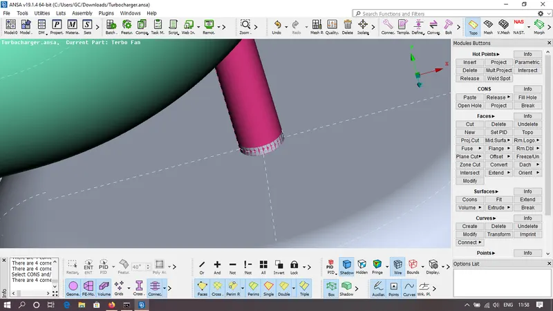
To find out the ovelapping surfaces first enables the pid mode, surfaces with glitched surfaces are the overlapping surfaces as shown in the image. Here pink colour surfaces are ovelapped on the green colour surface.
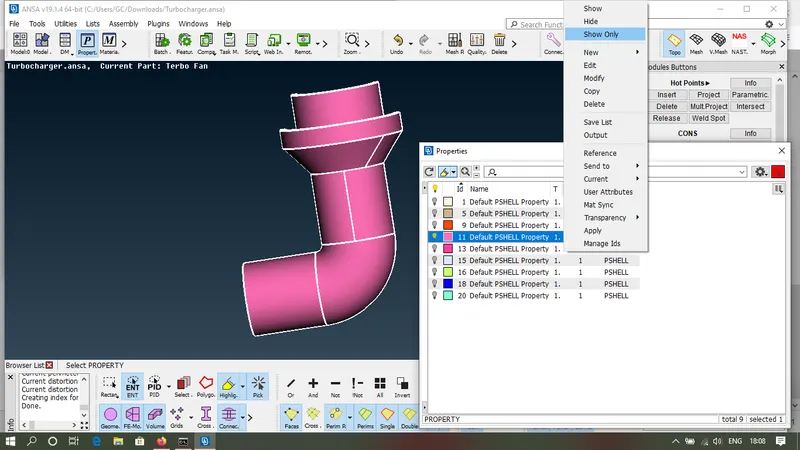
to delete these type of surfaces there are two methods.
1; identification of pid. identify the pid which is ovelapping such as in this case pid having name 11 default pshell propoerty is the overlapping pid. we can also confirm that by clicking right click on pid and enable show only option.then after identification we can delete that pid by following the layout.
PID MANAGER > PROPERTIES > SELECT PID > DELETE > OK
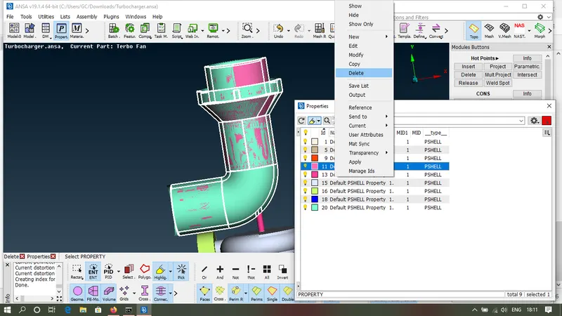
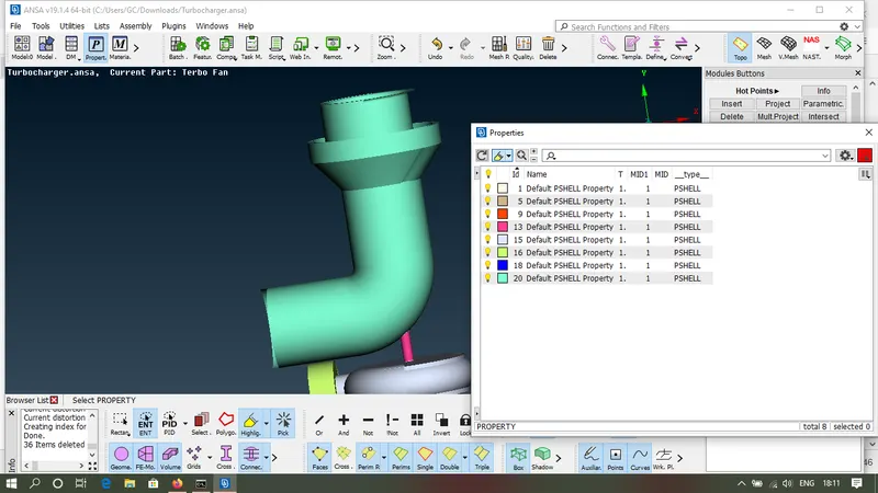
2; BY DELETING THE OVERALAPPING SURFACES.
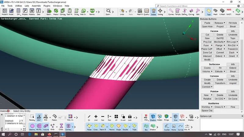
In this method first identify the overlapping surfaces by turning on the pid mode and after that select the cross hatch. cross hatch of the overlapped surfaces have the same colour as of the overlapped surface and then delete that surface.
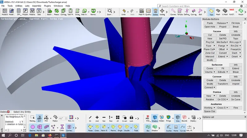
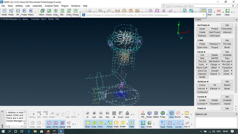
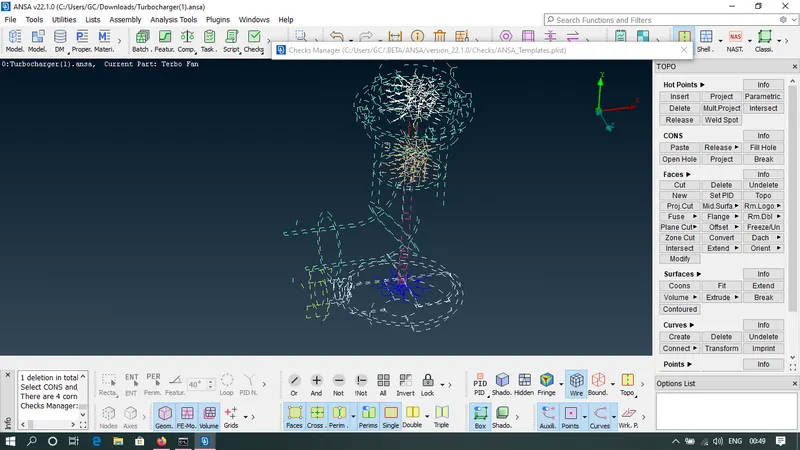
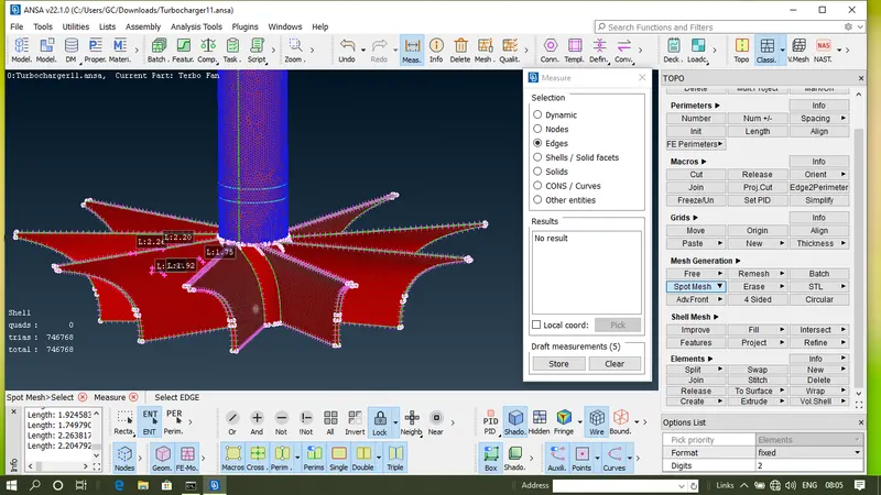
After the removal of the overlapped surface eliminate the single cons. single cons can be check by enabling the wire frame model. Single cons are the cons those are red in colour as shown in figure.
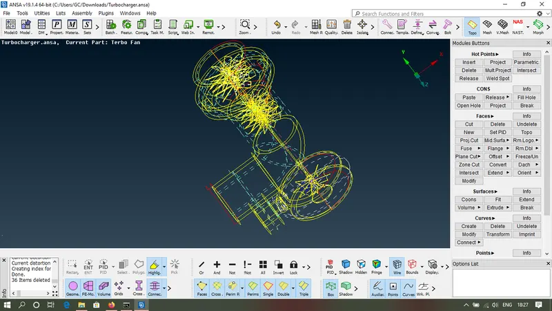
in the figure there are several red cons so start with deleting the single cons which is caused due extra porotion of the surface that is present at the outlet of the turbocharger.
so for deleting that surface first split the surafce in two diffrent surfaces using project cons method and then delete the surface that is present at outside portion of the turbocharger by following the layout as mentioned below.
TOPO > CONS > PROJECT > SELECT CON > MIDDLE KEY > SELECT FACE(The face that has to split in two faces) > MIDDLE KEY > DELETE > SELECT FACE > OK
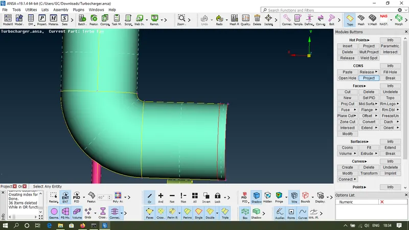
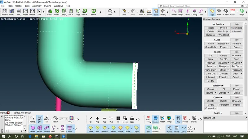
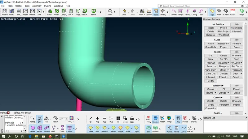
This single con can alse be eliminated by deleting the entire surface and then creating the surface.
now after the elimination of the single cons present at the outer part eliminate the single con present at upper side of turbocharger. This single con is presnt due to the incomplete surface as shown in figure.
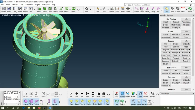
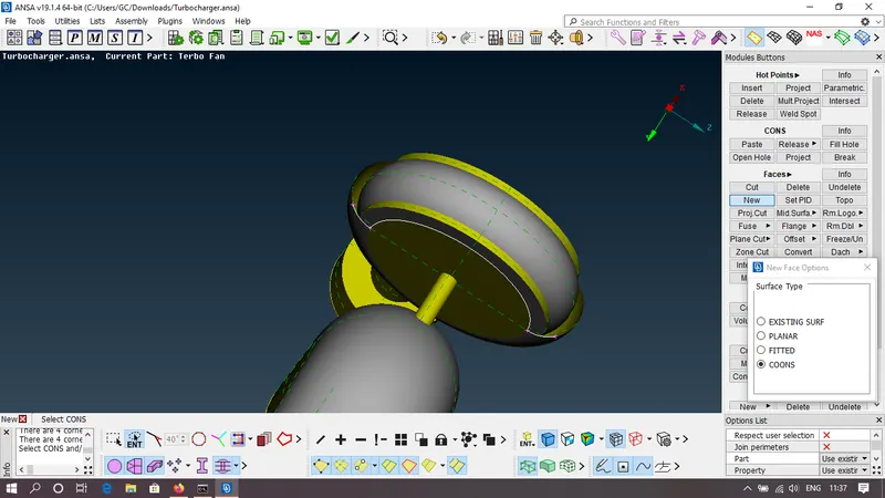
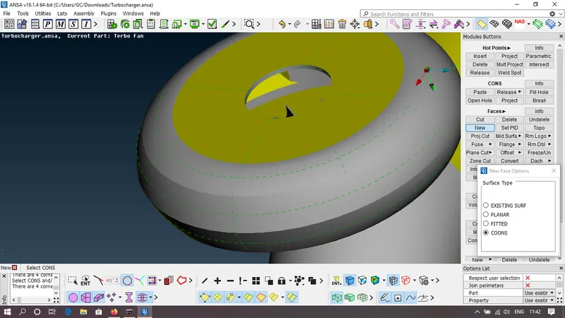
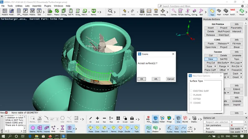
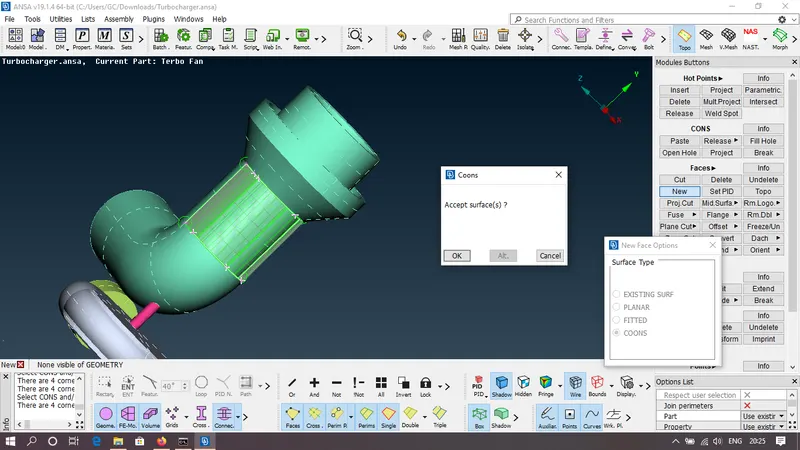
this single cons can be eliminated by new coons method. To apply this method follow the layout as shown below.
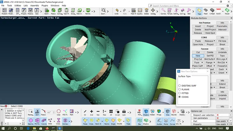
first hide the outer surfaces using boolen operator NOT due to which the defect will be visible more properly as shown in image.
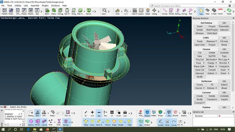
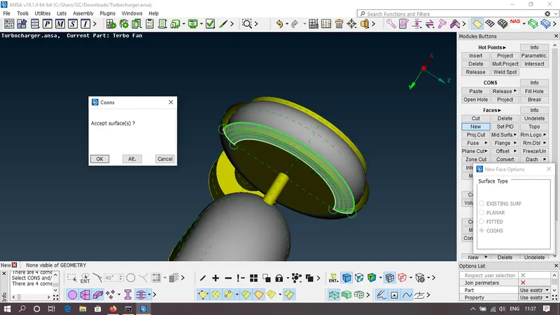
Now apply the new coons method by following the layout.
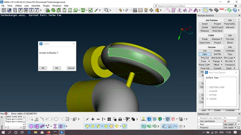
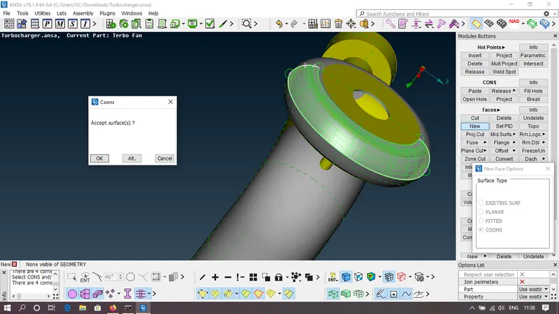
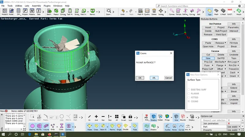
TOPO > FACES > ENTITY MODE> NEW > COONS > SELECT CONS > MIDDLE KEY > SELECT PREVIEW > OK.
Apply the new cons method in steps instead of in one go to obtain uniform surfaces.
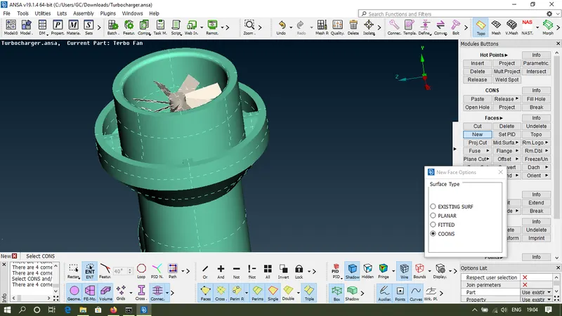
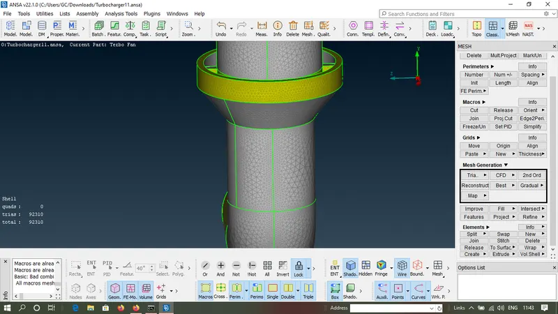
After eliminating the single cons at upper face nw its time to eliminate the curved surface that is present at the middle of turbocharger. As shown in the image.
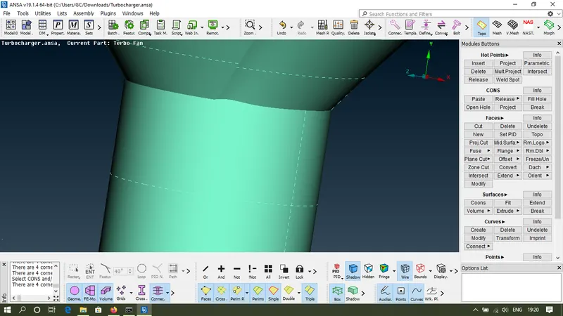
Eliminate the curve surface for that first delete the surface which posseses curve edges and then creating the surfaces using NEW COONS method as discussed earlier.
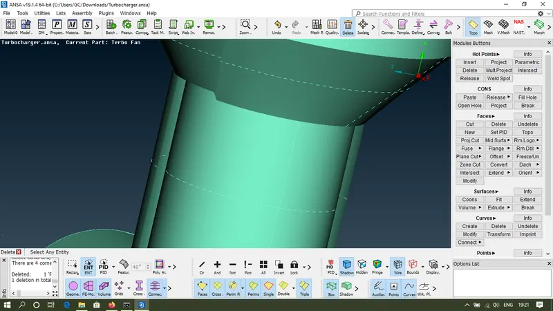
Project the cut at the surface that is penetrating inside the other surface. the cut can be created by using the layout as shown below.
TOPO > CUT > SELECT ONE NODE > SELECT ANOTHER NODE > MIDDLE KEY
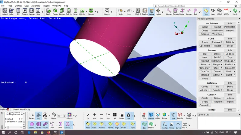
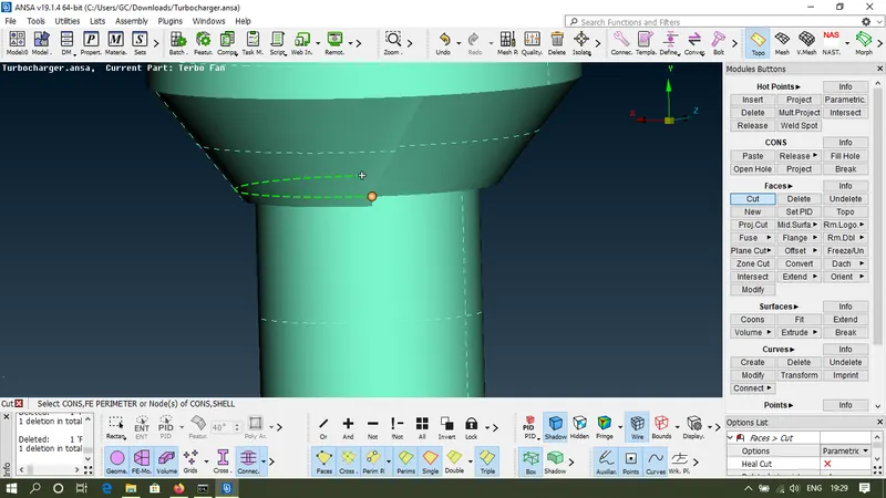
The cut will be created at the surface as shown in the image . the green line shown in the image is the preview of the cut that will be created at the surface.
To create the cut use the layout.
TOPO > FACES > CUT > SELECT ONE POINT > SELECT SECOND POINT.
CUT WILL BE CREATED ON THE SURFACE AS SHOWN IN IMAGE.
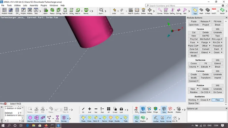
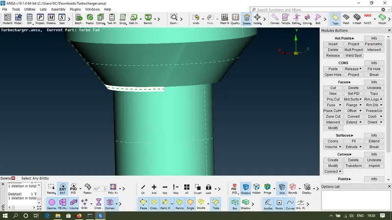
After creating the cut delete that extra surface that is penetrating inside the other surface.
after deleting the surface use NEW COONS method to redraw the surfaces.
After deleting the the surface project the hot points for selecting the cons of equal lengths. for inserting the hot points use the layout.
TOPO > INSERT > SELECT ONE POINT > SELECT OTHER POINT OPP0SITE TO FIRST POINT.
Then after inserting hot points use NEW COONS method to fill the surfaces .
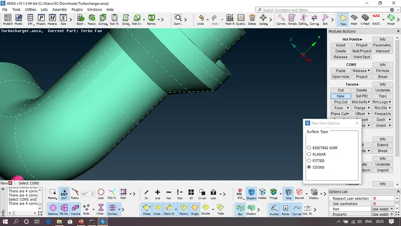
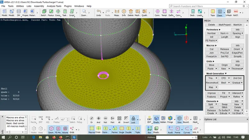
After performing the topological cleanup for the middle cection there is one single cons remain and that is present at the compressor section as show in the image below.
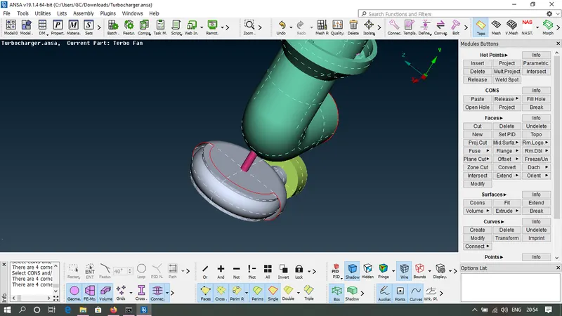
This single con is present due to absent of the surface at that area. THis single con can be eliminated by creating the surface in that region and the surface can be created by two methods.
1; using TRANSFORM OPTION
2; By filling the surface layer by layer.
USING THE TRANSFORM OPTION:
The layout for using the transorm option are shown below.
If in the CAD file three hot points are not present then crete them using the layout.
TOPO > HOT POINTS > PARAMETRIC > GIVE DISTSNCE AS 0.5 > SELECT DIRECTION BY CLICKING ON ANY HOT POINT > MIDDLE KEY.
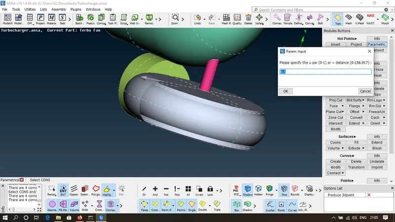
TRANSFORM > COPY > SELECT ENTITY(The entity which has to transfer in this case the remaining circular surface) > MIDDLE KEY > COPY ENTITIES WINDOW POPUP ON SCREEN MOVE TO SYMMETRY OPTION ON THAT WINDOW > SELECT OPTION MIRROR 3 POINTS PLANE > SELECT THREE HOT POINTS > MIDDLE KEY > OK > FINISH.
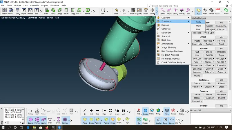
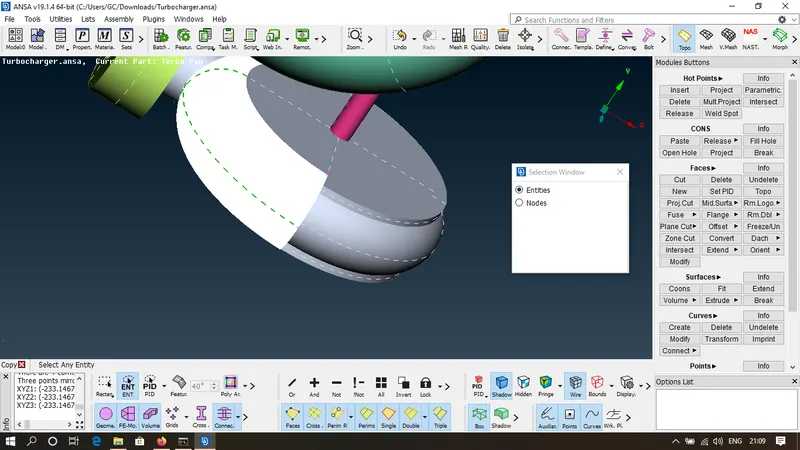
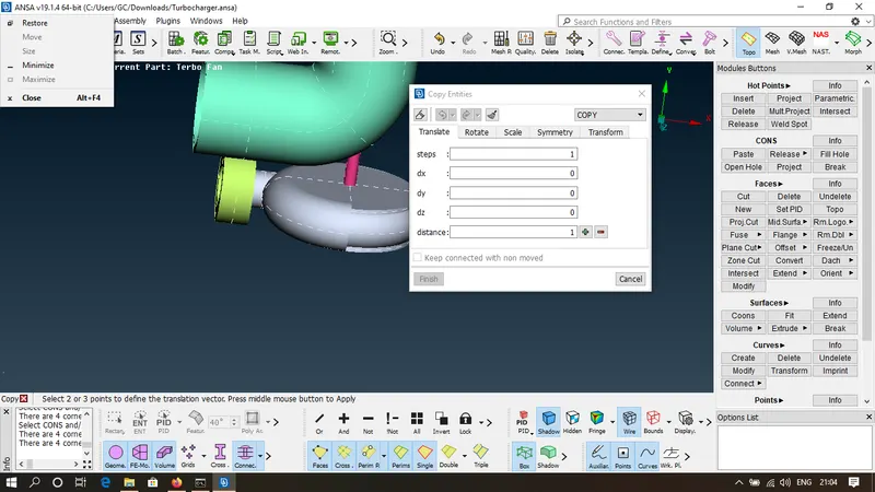
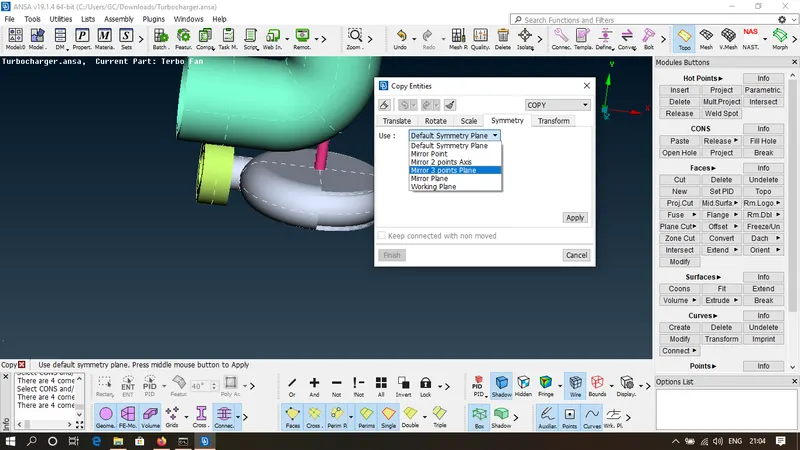
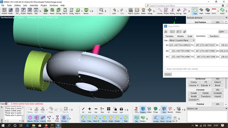
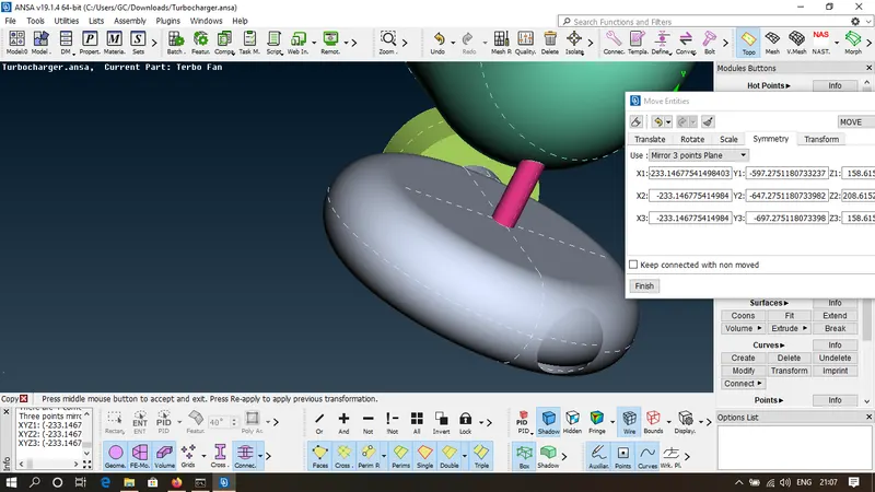
As shown in the image the similar type of surface has been created at another side of the compressor casing. now fill that hole using fill hole option. for applying the fill hole option follow the layout as shown below.
TOPO > CONS > FILL HOLE > SELECT CONS > MIDDLE KEY.

As we enable the single cons so at the compressor where surface has been created will show the single cons both at upper and lowe side of the compressor.to eliminate that single cons first release that cons manually release in the sense as there are cons that is formed due to combination of two surface but it shows red colour instead of yellow colour so first release that cons release in the sense first split that cons in two single cons using RELEASE OPTION .The procedure to release the cons is
TOPO > CONS > RELEASE > SELECT CONS > MIDDLE KEY
Now after releasing the cons merge that cons in two single cons using topo option.
TOPO > FACES > TOPO >BOX SELECTION > MIDDLE KEY
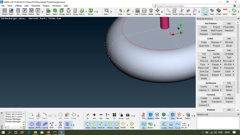
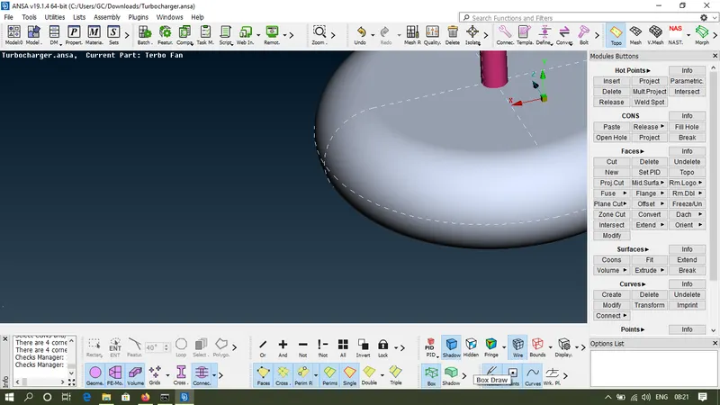
So the take away from this point is if the single cons are presnt due to the combination of two surfaces and tripple cons presnt due to combination of two surfaces then we can eliminate them by first releasing the cons using RELEASE CONS method and then mergre them using TOPO FACES option. RELEASE cons and TOPO faces are both opposite to each other.
single cons can also be eliminated by using PROJECT CONS method where a single con is projecting on other surface. The layout for that is shown below. Some times topo option is not working then use this method to eliminate single cons.
TOPO > CONS > PROJECT > SELECT RED CONS > SELECT THE SURFACE WHERE THAT SINGLE CONS HAS TO BE PROJECTED > MIDDLE KEY.
BY FILLING THE SURFACE LAYER BY LAYER.
This the method where the diffrent surfaces are created as layer by layer.To crete the diffrent surfaces first insert some hot points at both side on the surface then create the diffrent surfaces using NEW COONS method.
to insert hot ponts use TOPO > INSERT > SELECT HOT POINTS
to create surfaces use TOPO > FACES > NEW > COONS > SELECT COONS > PRESS OK.