Week 2 Challenge : Surface meshing on a Pressure valve
AIM: SURFACE MESHING ON PRESSURE VALVE.
PROBLEM STATEMENT:
For the given model, check for the geometrical errors and perform Topology cleanup accordingly. Set three different target lengths as three different cases and mesh the model.
- Target length = 1mm, 3 mm and 5 mm (i.e. 3 cases)
- Element type = Tria
Apply any one target length from the above at a time for the entire model as One case. Submit 3 different models for 3 cases.
Write a detailed report on your meshing process and also mention which case is giving good results along with the reason.
PROCEDURE:
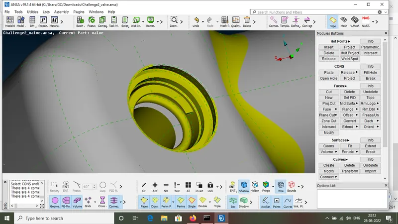
PERFORM TOPOLOGICAL GEOMETRIC CLEANUP SUCH AS REDUCTION OF SINGLE CONS, TRIPPLE CONS, CRACKS.
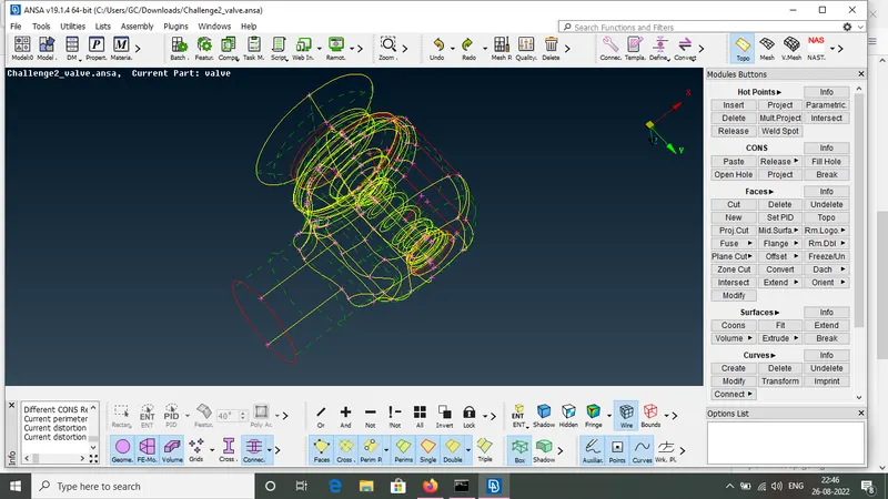
TO PERFORM THE GEOMETRIC CLEANUP USE THE FOLLOWING STEPS.
1) Go to topo mode
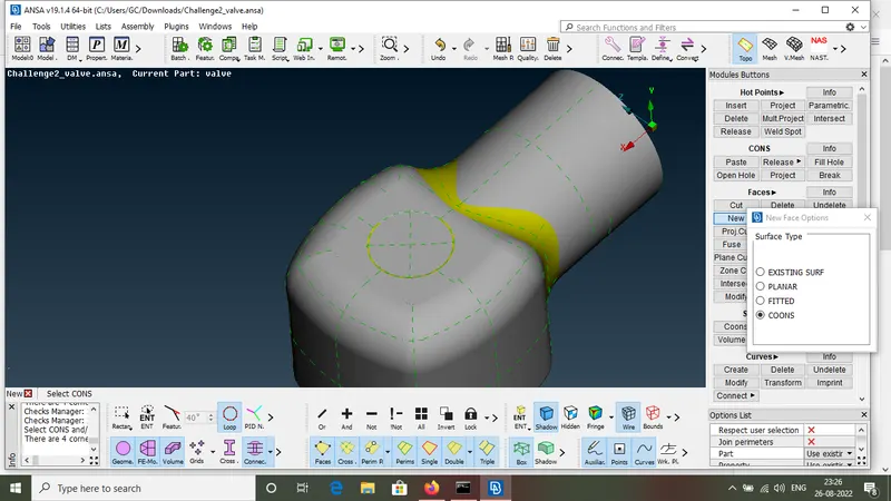
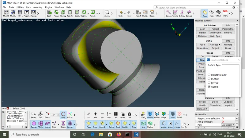
2)IN TOPO MODE THERE IS AN FACE OPTION MODE INSIDE THE FACE OPTION GO FOR THE NEW OPTION IN NEW OPTION THERE ARE DIFFRENT SURFACE TYPE PRESENT SUCH AS EXISTING SURFACE, PLANER , FITTED, COONS GO FOR THE COONS SURFACE TYPE.
TOPO > FACES > NEW > COONS > SELECT CONS USING MIDDLE KEY > OK
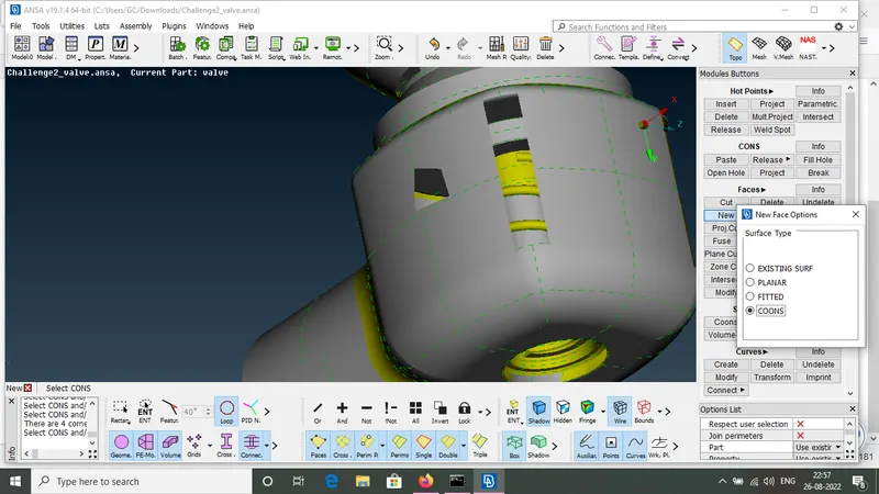
The above method is used to fill the open surfaces and cracks.
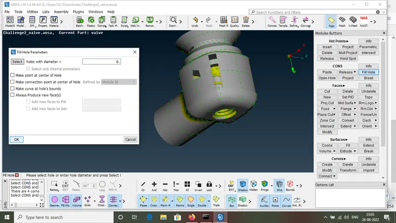
There is one another method used to fill the open surfaces and that method is fill hole method . the diffrence between fill hole and new coons method is in fill hole method we obtain the uniform surface through out while in new coons method we obtain non uniform surface
for performing the fill hole methd follow the following layout.
TOPO > CONS > FILL HOLE > SELECT HOLE USING MIDDLE KEY OF MOUSE > OK
3) PERFORM TOPOLOGICAL CLEANUP USING ANY ONE OF ABOVE METHOD AND MAKE SURE THERE IS NOT ANY TYPE OF TOPOLOGICAL GEOMETRICAL CLEANUP REMAINS.
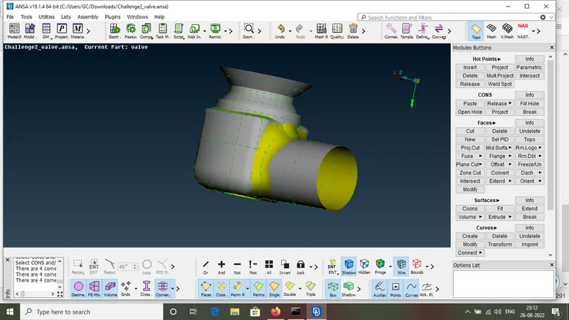
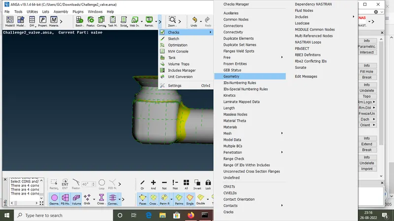
To check for geometrical cleanup follow the following layout.
CHECKS > GEOMETRY > EXECUTE .
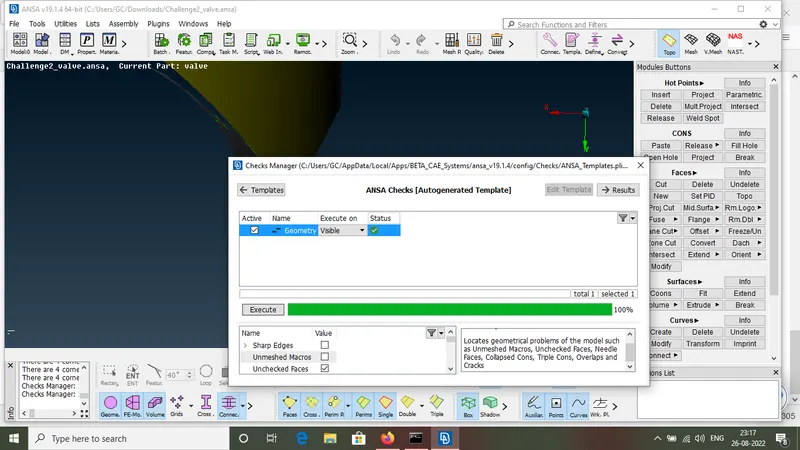
IN THE ABOVE PICTURE AFTER EXECUTUTION IF STATUS IS RIGHT THAT MEANS THERE IS NO TOPOLOGICAL CLEAUP REMAIN.
4) ALL THE SURFACE MUST BE CLOSED BEFORE PERFORMING THE SURFACE MESH.
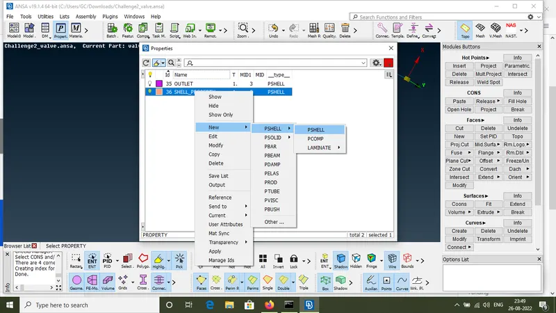
5) Before going for surface mesh create some pid's using the layout as mention below.
PID MANAGER > PROPERTIES > RIGHT CLICK > NEW > P SHELL > CLICK ON P SHELL > RENAME .
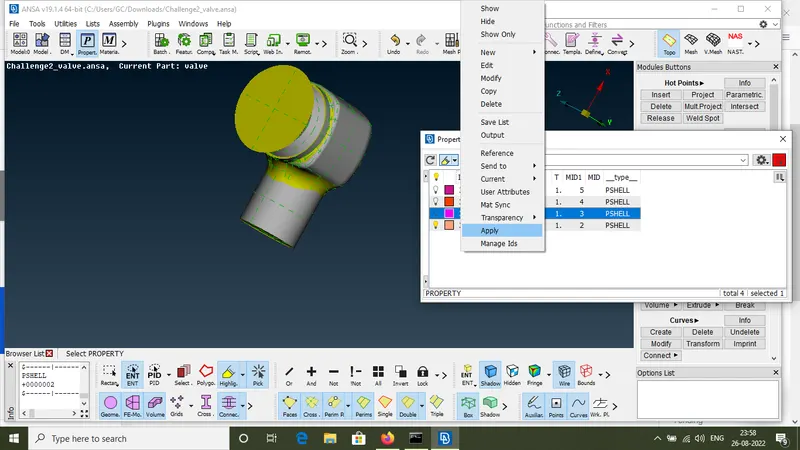
6) After creating some pids assign them using layout as shown.
RIGHT CLICK ON PID NAME > APPLY > SELECT THE CROSS HATCH OF SURFACE THAT HAS TO BE ASSIGNED > MIDDLE KEY.
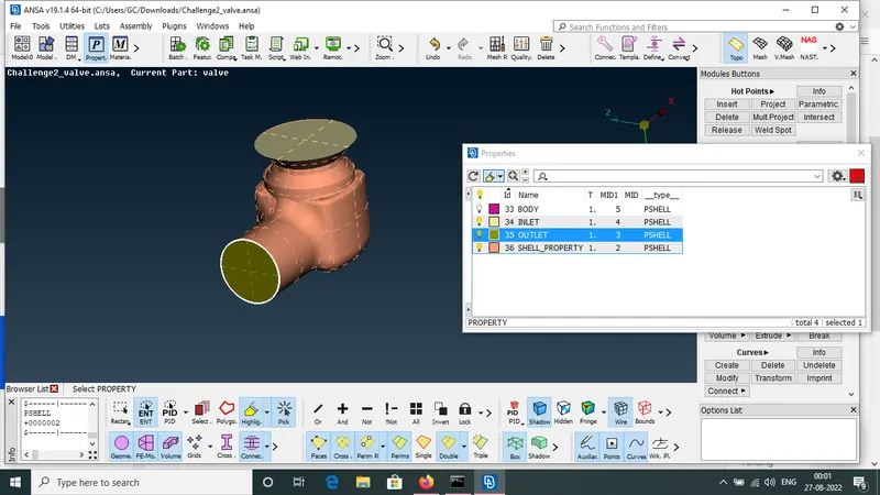
After creating pids for outer parts creat pids for inner parts of pressure vessel such as spring, valve head, coloumn, base surface by following the same layout and assign them using the same layout.
for creating the pids for the inner parts use the boolen operators such as NOT for isolating them, lock option etc.
use the bulb button for isolating the one surface on the screen by disabling the bulb button of other pids.
for selecting the pid one at a time use pid region option.
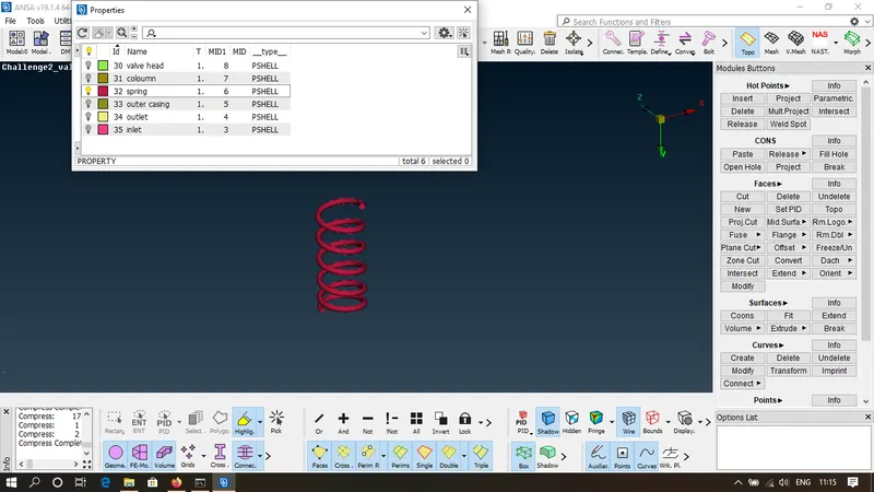
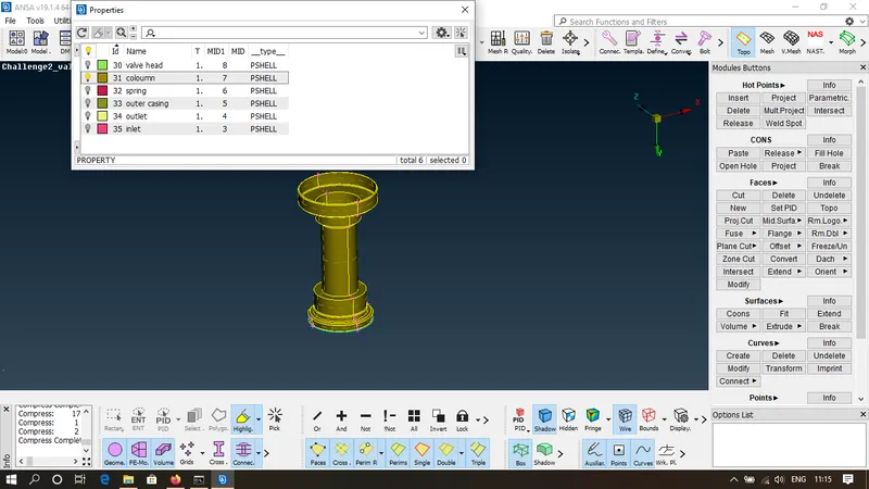
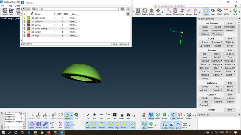
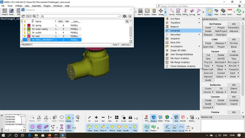
7) After assigning pids for every part delete the dummy property "36 shell property" using compress option by following the layout.
PID MANAGER > SELECT 36 SHELL PROPERTY > SELECT COMPRESS > OK .
8) Minimise all the small surfaces, sharp edges, whose dimensions are less than element mesh size such as 5mm. small surfaces and sharp edges must be eliminated because this will results in unstructured mesh. Sharp edges and small surfaces posseses smaller dimensions than the element mesh size due to ehich it is difficult to capture these surfaces for meshing having greater element mesh size. it will increase off elements, aspect ratio, skewness.
To remove these smaller surfaces merge them with neighbouring surfaces by following the layout.
MESH > MACROS > JOIN > CLICK ON CONS.
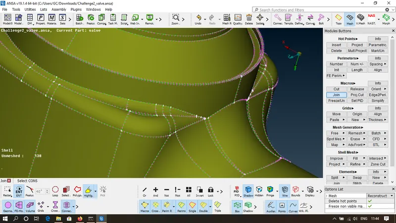
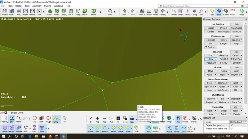
9) use topo option to convert all the single cons in to double cons. that means while using the join option surfaces got disconnected, to connect all the surfaces use the topo option.
topo option is used by following the layout.
TOPO > FACES > TOPO > BOX SELECTION OF WHOLE CAD FILE > OK .
In topo use box selection because it will only select the single cons from the whole geometry.
disable double and tripple cons and only enable single cons there is no single cons present in geometry as shown in below image.
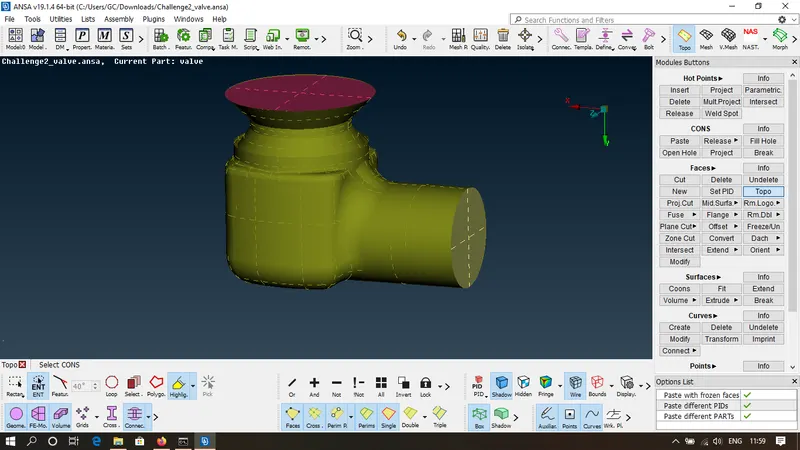
hence all the geometrical cleanup has been performed now perform surface mesh in this geometry with diffrent cases as mentioned in the problem statement.
10)
CASE 1 : ELEMENT TYPE - TRIA
TARGET LENGTH - 5mm
step 1) Assign mesh length for perimeter by selecting BOX SELETION and give target lenth as 5mm.
step 2) Assign mesh length for macros by selecting BOX SELECTION and give target length as 5mm.
step 3) Go to mesh parameter and assign target lenth as 5mm and minimum length as 3mm and maximum length as 7mm and assign element type as tria.
step 4) click on quality criteria assign minimum length as 3mm and maximum length as 7mm and click on ok.
After performing the above operation go to pid manager and by enabling and disabling the bulb key perform the meshing for each and every pids.
now perform the spot mesh using the layout.
MESH > MESH GENERATION > LONG PRESS ON SPOT MESH > VISIBLE > BOX SELECTION OF CAD FILE > OK.
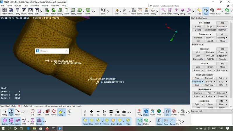
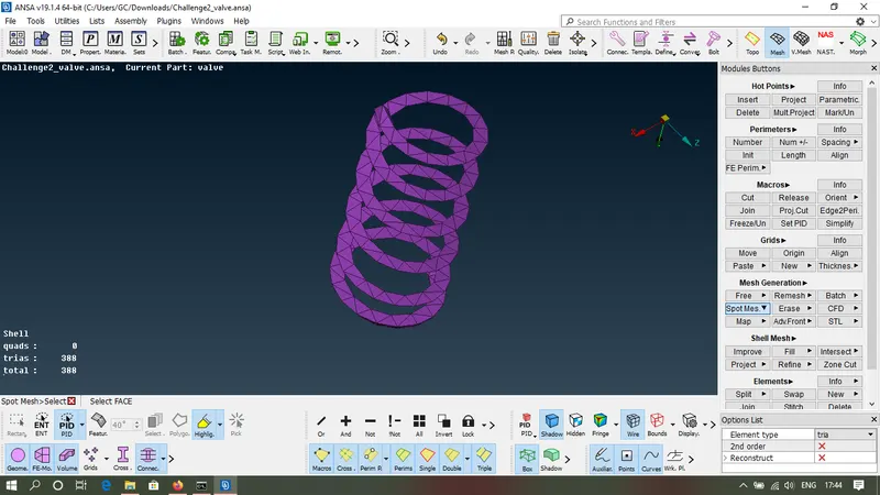
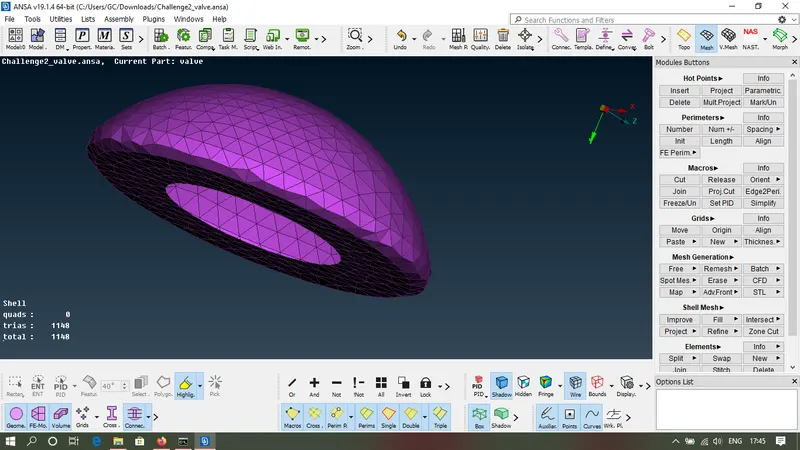
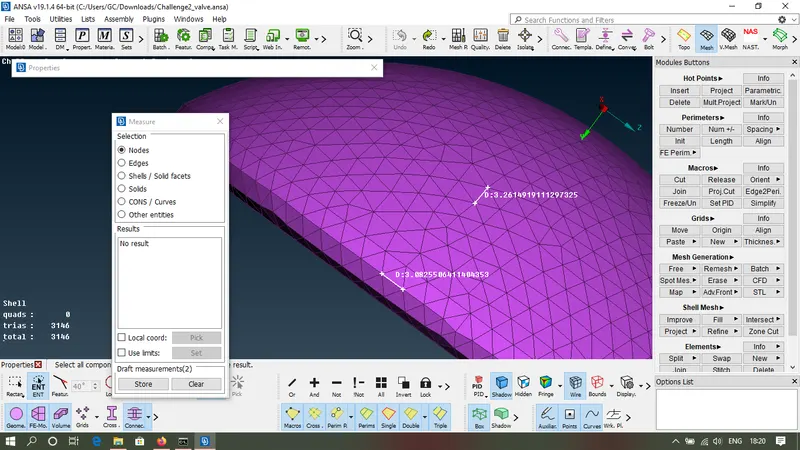
Measure the distance between two nodes with the help of measure tool.
The distance between the two nodes is between 3mm to 7mm. the distance at the sharp edges will be closure to 3mm and at surface it wil be between 5mm.
in the above images spring looks like flat surface after performing the mesh having target length of 5mm. This is because the diameter of the spring is less than the target length due to which after performing tha spot mesh the springs becomes flat. At the corner of valve head the surface looks like irregular because of the high value og target length.
To minimise these errors use smaller target length.
To perform the mesh having the target length of 3mm first erase the mesh that is already present by following the steps.
MESH > MESH GENERATION > ERASE > BOX SELECTION OF CAD FILE > PRESS LEFT KEY.
CASE 2 : ELEMENT TYPE - TRIA
TARGET LENGTH - 3mm
step 1) Assign mesh length for perimeter by selecting BOX SELETION and give target lenth as 3mm.
step 2) Assign mesh length for macros by selecting BOX SELECTION and give target length as 3mm.
step 3) Go to mesh parameter and assign target lenth as 5mm and minimum length as 1mm and maximum length as 5mm and assign element type as tria.
step 4) click on quality criteria assign minimum length as 1mm and maximum length as 5mm and click on ok.
After performing the above operation go to pid manager and by enabling and disabling the bulb key perform the meshing for each and every pids.
now perform the spot mesh using the layout.
MESH > MESH GENERATION > LONG PRESS ON SPOT MESH > VISIBLE > BOX SELECTION OF CAD FILE > OK.
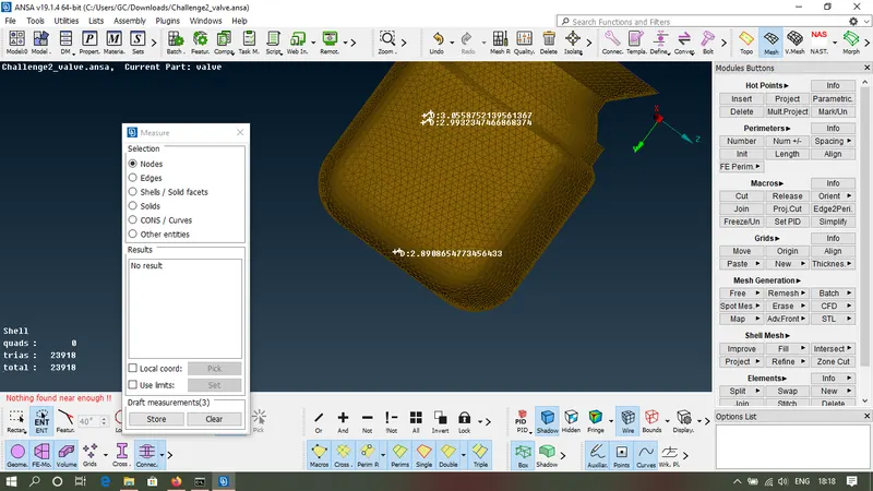
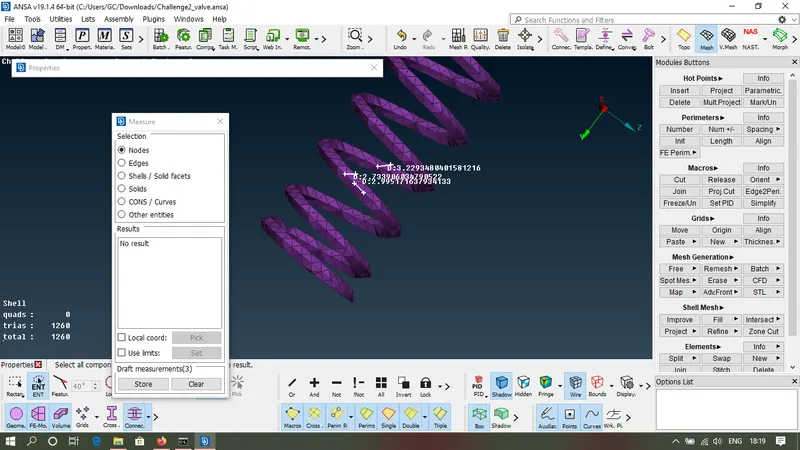
In the above images as we have seen that the spring becomes more circular and valve head surface become more regular by using the smaller target length of 3mm.
By using smaller target lenth for the meshing it will take more computational time for the meshing but gives more accurate results.
Let us see what happens if the target length is 1mm.
To perform the mesh having the target length of 1mm first erase the mesh that is already present by following the steps.
MESH > MESH GENERATION > ERASE > BOX SELECTION OF CAD FILE > PRESS LEFT KEY.
CASE 3: ELEMENT TYPE - TRIA
TARGET LENGTH - 1mm
step 1) Assign mesh length for perimeter by selecting BOX SELETION and give target lenth as 1mm.
step 2) Assign mesh length for macros by selecting BOX SELECTION and give target length as 1mm.
step 3) Go to mesh parameter and assign target lenth as 5mm and minimum length as 0.5mm and maximum length as 2mm and assign element type as tria.
step 4) click on quality criteria assign minimum length as 0.5mm and maximum length as 2mm and click on ok.
After performing the above operation go to pid manager and by enabling and disabling the bulb key perform the meshing for each and every pids.
now perform the spot mesh using the layout.
MESH > MESH GENERATION > LONG PRESS ON SPOT MESH > VISIBLE > BOX SELECTION OF CAD FILE > OK.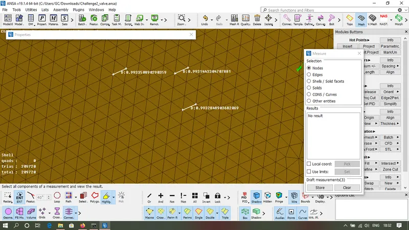
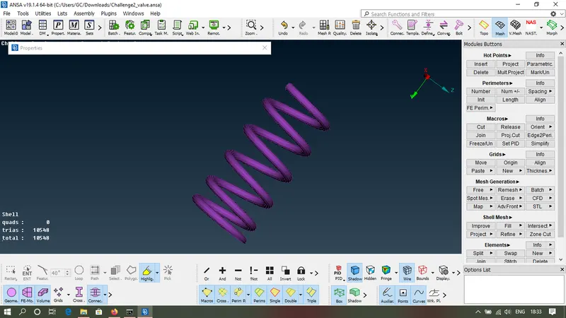
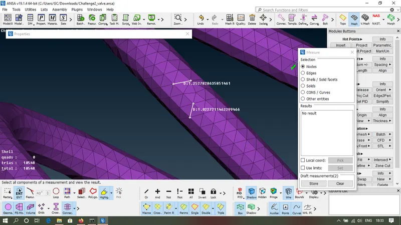
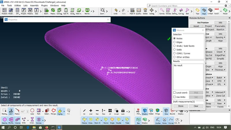
So performing the mesh with smaller target lenth results in
> regular circular surface of spring and pressure valve.
> reduction of off elements.
> meshing will perform at every region of cad file.