Project 1 : CFD Meshing for Tesla Cyber Truck
AIM : CFD MESHING FOR TESLA CYBER TRUCK.
PROBLEM STATEMENT: For the given model, check and solve all geometrical errors and Assign appropriate PIDs. Perform meshing with the suitable Target length and element Quality criteria.
Target lengths for the different parts of a model are as follow:
1) Window - 2mm
2) Rims and tyres - 2mm
3) Body - 3mm
4) Top domain of close contour - 100mm
5) Bottom domain of close contour - 20mm
PROCEDURE :
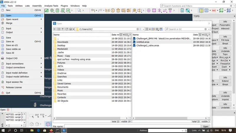
> Open the file in ANSA window by clicking on the file menu present at top left corner of the ANSA window.
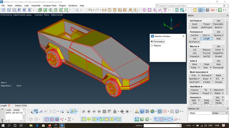
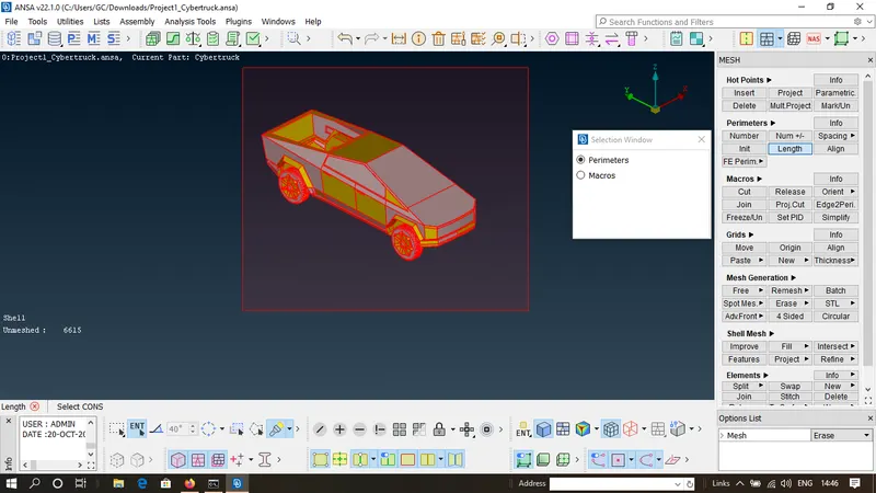
> Assign the perimeter length as 1mm for the file due to which the curves present at the body become circular or simply use FINE option.
To assign the perimeter length follow CLASSIC MESH > PERIMETER > LENGTH > SELECT PERIMTER > BOX SELECTION > MIDDLE KEY > ENTER TARGET LENGTH AS 1MM > OK.
To use fine option follow TOPO > AUXILLARIES > FINE.
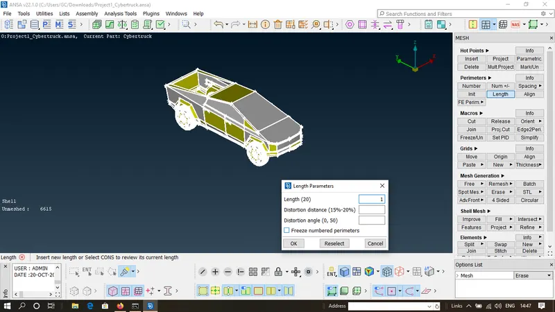
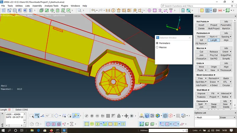
> Perform all the topological cleanup like elimination of single cons, tripple cons,cracks,penetration errors etc.
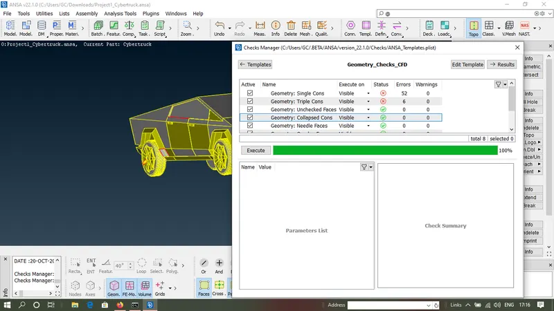
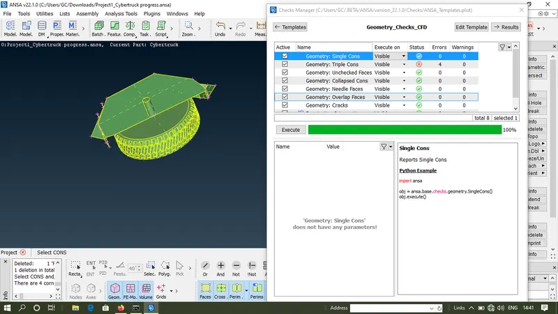
Before eliminating the topological error first check all the errors present inside the file using the checks manager.
CHECKS > CHECKS MANAGER > CFD CHECKS GEOMETRY > EXECUTE.
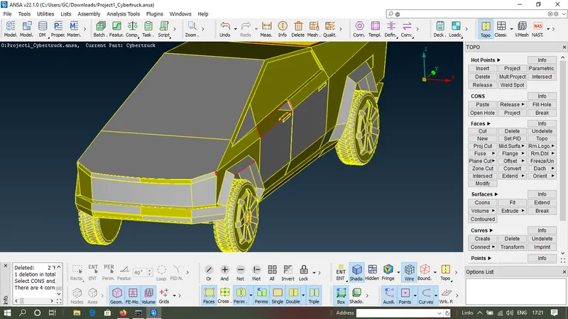
All the geometrical errors will appear on the screen as shown in image below.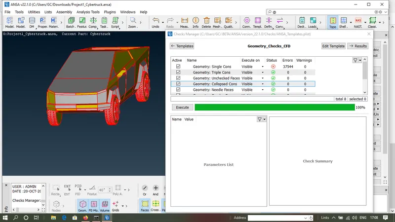
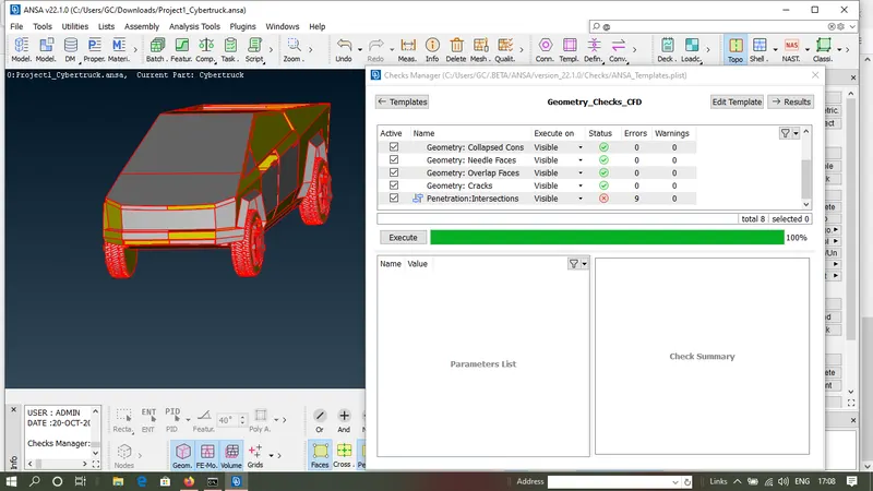
Perform the TOPO option by following the layout.
TOPO > FACES > TOPO > BOX SELECTION > OK
It will eliminate the single cons present on the body as shownin image after performing the topo the quantity of single cons reduced.
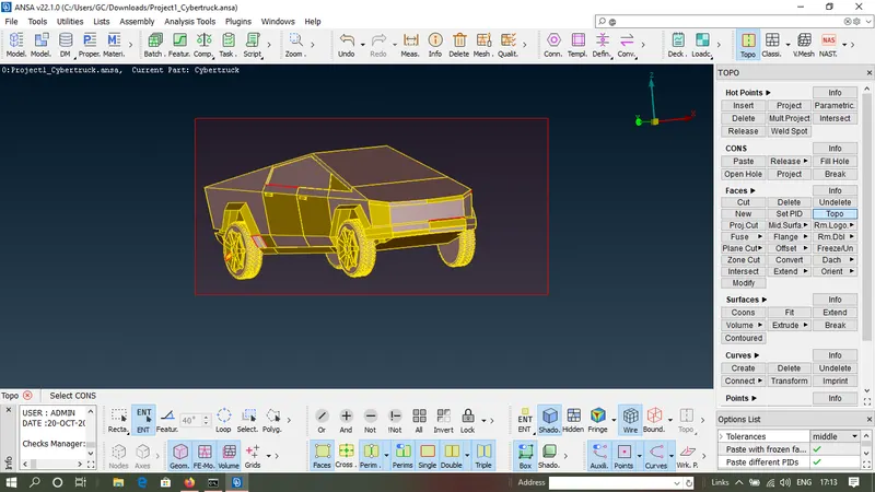
> Perform the topological cleanup such as elimination of the single cons,tripple cons,penetration,needle,corner cracks etc.
> To start the topological cleanup start with the single cons and open surfaces.
> eliminate all the tripple cons and single cons and penetration error by simply deleting the surfaces.
> To check whether the topological cleanup completed use CHECKS by following the layout
CHECKS > CHECKS MANAGER > CFD CHECKS GEOMETRY > EXECUTE.
> In this door portion remove all the tripple cons by deleting the extra surfaces and overlapping surfaces, confirm the selection ogf the surfaces by using wire frame model.
> Before performing the topological cleanup checks the error using the checks manager.
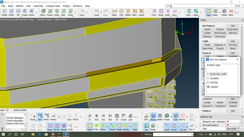
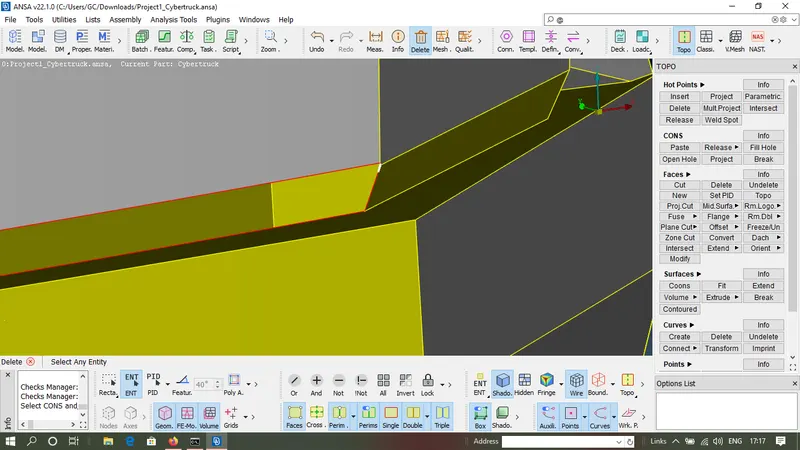
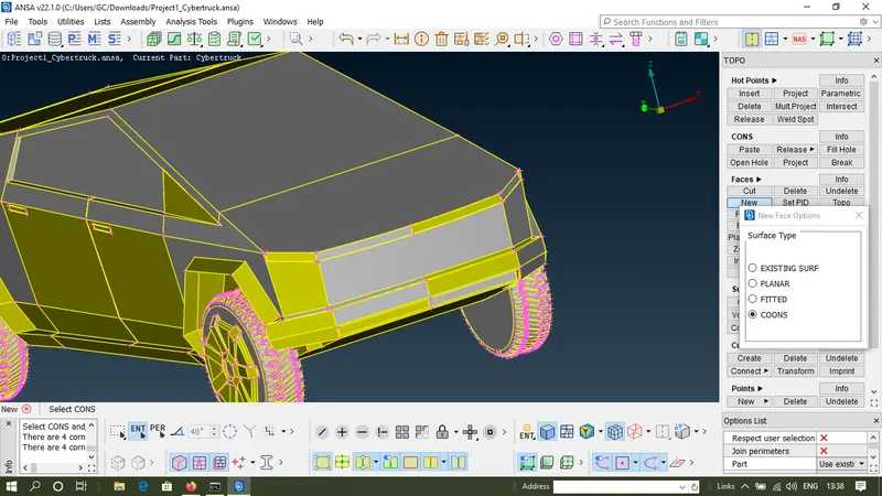
> close all the open surfaces using the NEW CONS method by following the layout.
TOPO > FACES > NEW > SELECT LOOP MODE FOR SELECTING THE CONS > SELECT FITTED OPTION > SELECT THE CONS > OK.
> Confirm the selection of the cons using wire frame model.
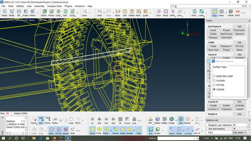
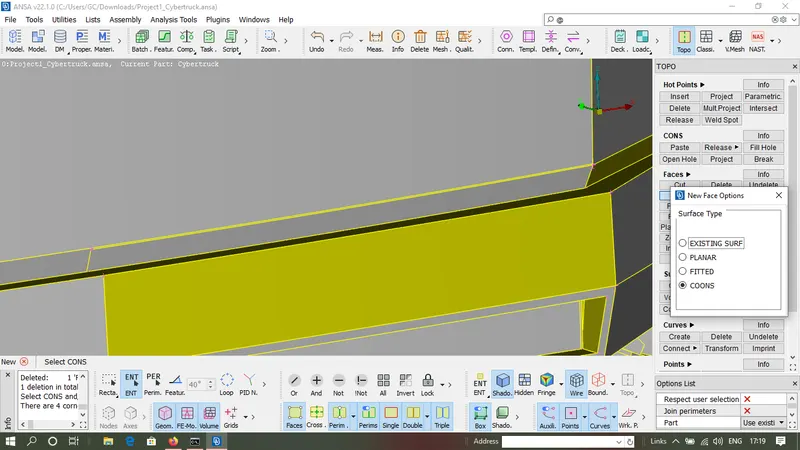
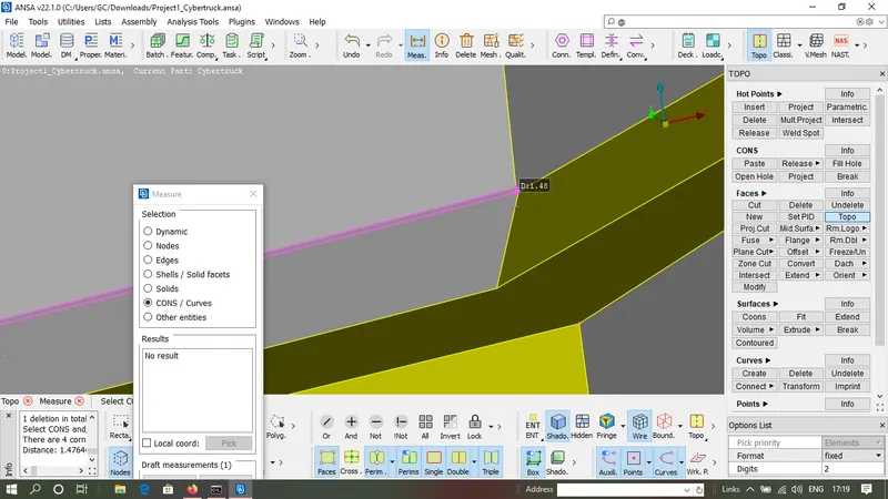
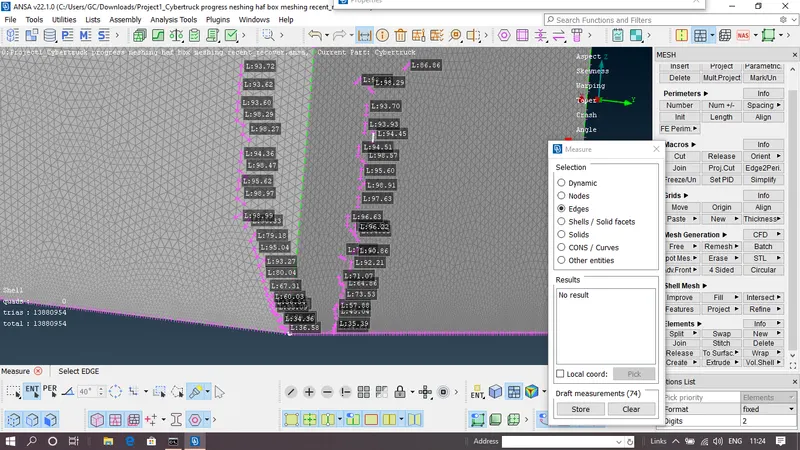
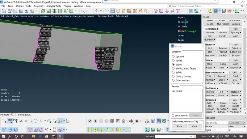
> Check the dimensions of the small edges present at the body using the MEASURE option.
> Delete all the small edges whose dimensions are less the target length.
> To measure the distance use measure option present at top of the ANSA window
MEASURE > EDGES > SELECT EDGE
> Delete all the edges whose length are less then the target length using universal delete option and create the surface using TOPO > FACES > CONS > ENT > SELECT CONS > OK.
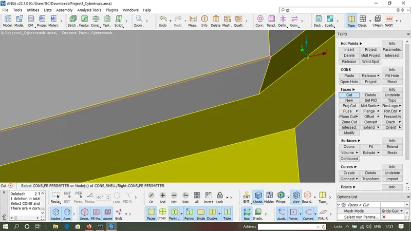
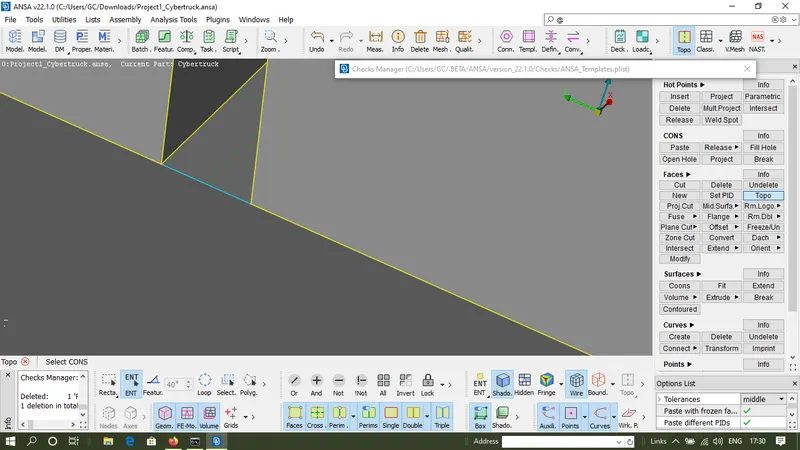
To remove this type of penetration errors first create the small cut at the parent surfaces by following the layout given below and then then delete those small surface by using the universal delete option.
TOPO > FACES > CUT > SELECT ONE POINT > SELECT ANOTHER POINT > MIDDLE KEY.
After eliminating of the penetration error fill the surfaces by following the layout
TOPO > FACES > NEW > SELECT FITTED OPTION > SELECT LOOP MODE > SELECT SURAFCES > OK.
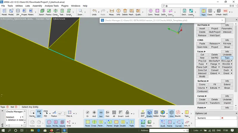
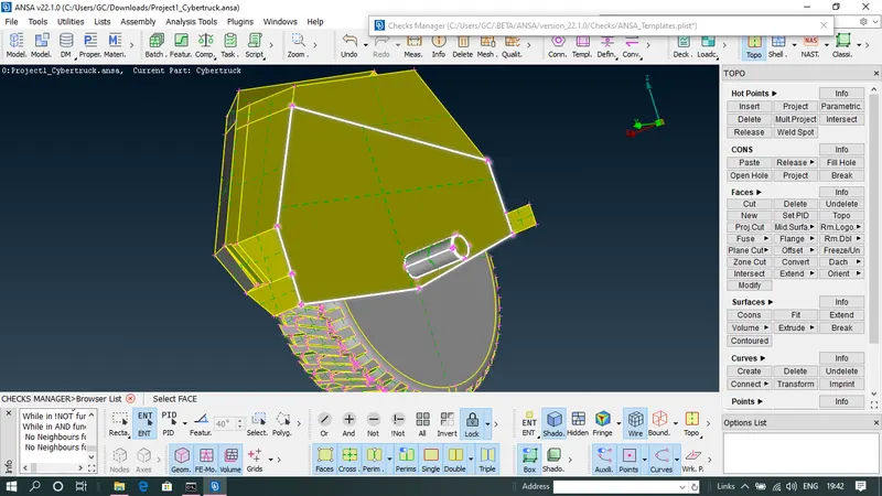
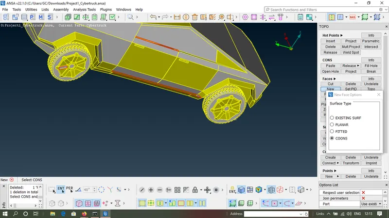
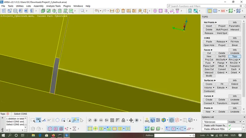
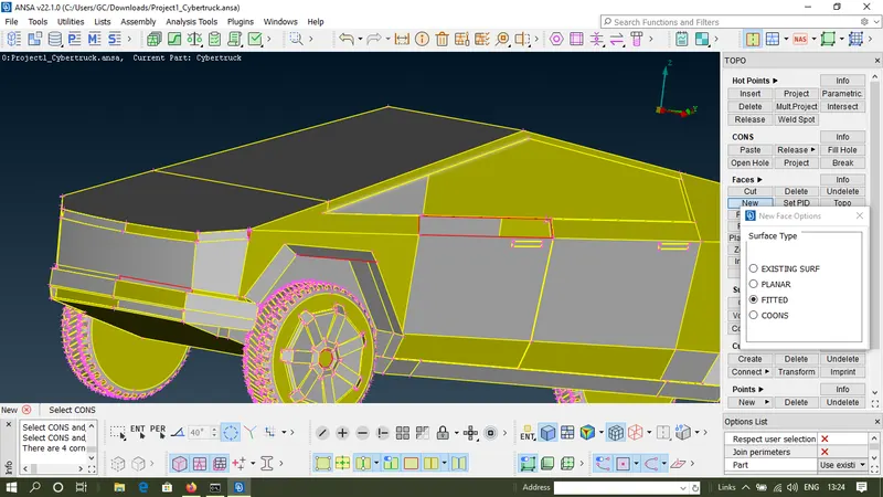
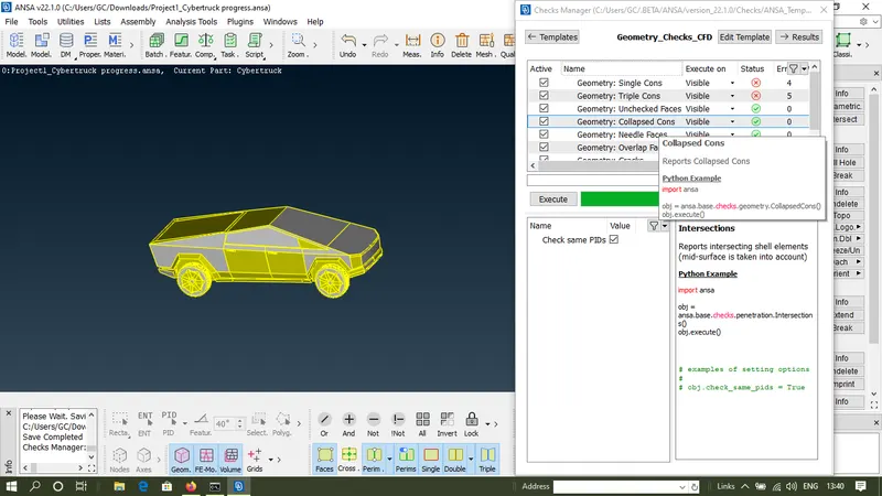
In the above image after performing the topological cleanup for all the parts of the cybertruck checks the errors using the checks manager. follow the same procedure for all other PIDs.
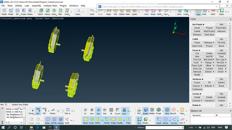
Isolate the particular pid in this case rims and tyres using the boolen operator NOT and then use LOCK option.
check all the errors using checks manager.
perform all the topological cleanup for eliminating the errors.
After performing topological clean up checks the geometrical errors using checks manager.
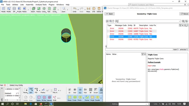
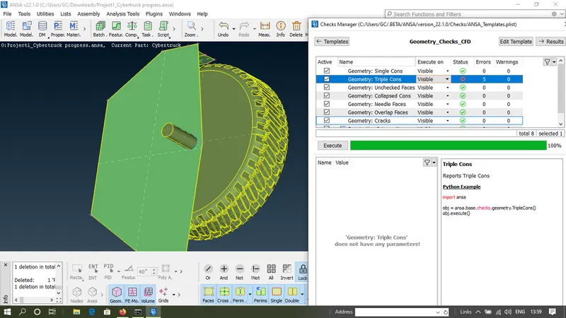
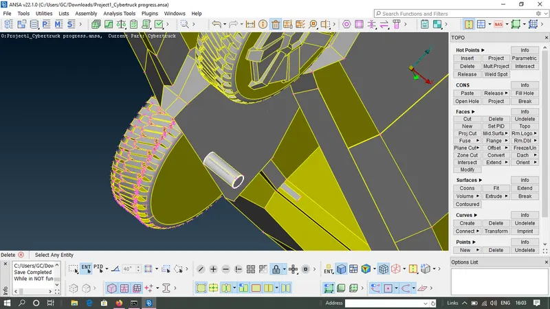
Delete the shaft that is penetrating over the surfaces to eliminate the penetration error.
Fill the hole that is created after the deletion of the shaft by the diffrent methods such as NEW CONS method or fill hole option by following the layout.
TOPO > FACES > FILL HOLE > SELECT LOOP OPTION > SELECT THE OPEN SURFACES > MIDDLE KEY > OK
TOPO > FACES > NEW > SELECT FITTED OPTION > SELECT LOOP MODE > SELECT SURAFCES > OK
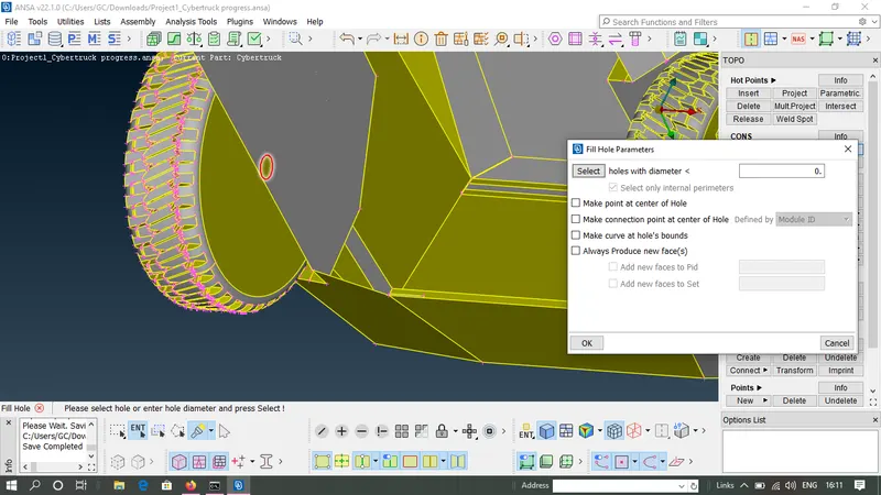
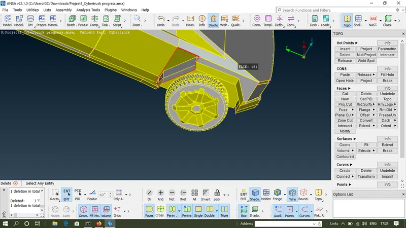
In the above image after performing the topological cleanup for all the parts of the CYBERTRUCK checks the errors using the checks manager. follow the same procedure for diffrent diffrent PIDs.
Isolate the particular pid start with window and tyre using the boolen operator NOT and then use LOCK option.
check all the errors using checks manager.
perform all the topological cleanup for eliminating the errors.
After performing topological clean up checks the geometrical errors using checks manager for the diffrent pids such as body, tyre ,window.
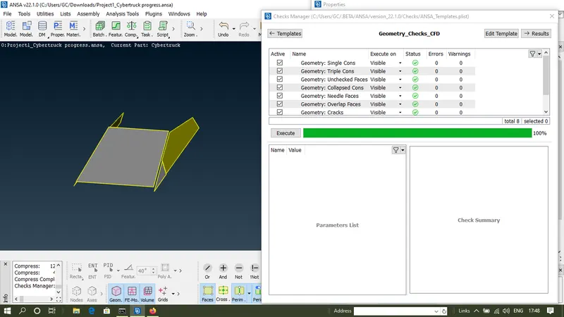
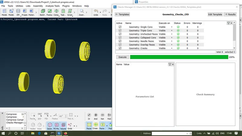
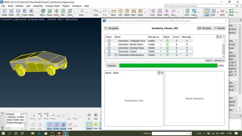
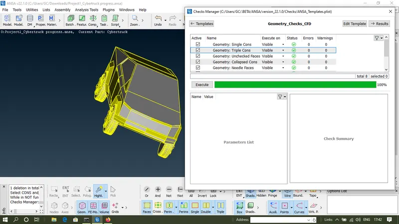
In the above image after performing the topological cleanup use the check manager where it shows all the geometrical errors has been resolved.
After the completion of topological cleanup assign some PIDs by following the layout
PROPERTY > PID MANAGER > RIGHT CLICK > NEW > ASSIGN NAME > OK > RIGHT CLICK ON PID > APPLY > SELECT THE PID USING BOX SELECTION > MIDDLE KEY.
Assign three pids as shown in image below.
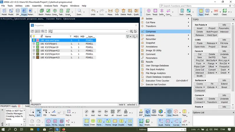
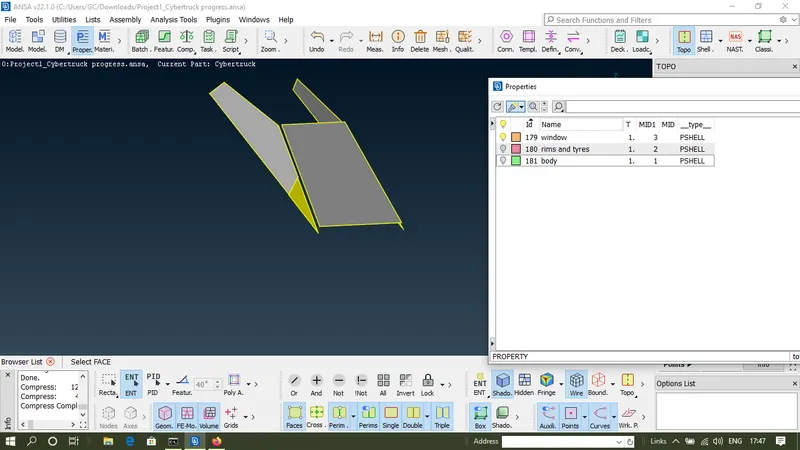
> Perform the meshing on each pids by hiding the other pids by turning off the bulb button present in the pid manager star with window and tyres.
> To perform the meshing over the window and tyres use target length as 2mm.
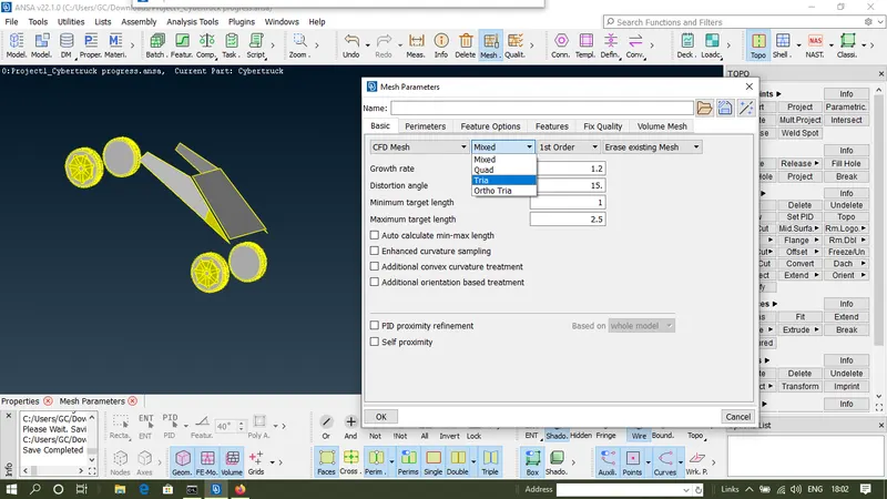
> for performing the pids follows the four steps.
1) MESH PARAMETER > CFD MESH > MINIMUM LENGTH AS 1 MM > MAXIMUM LENGTH AS 3.5MM > ELEMENT TYPE AS TRIA .
2) QUALITY CRITERIA > DISABLE ALL THE PARAMETER EXCEPT ASPECT RATIO, SKEWNESS , MINIMUM LENTH AS 1MM, MAXIMUM LENGTH AS 3.5MM > APPLY > OK.
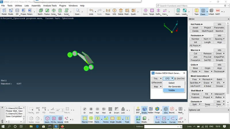
3) CLASSIC MESH > PERIMETER > LENGTH > MACROS > BOX SELECTION OF THE PID > MIDDLE KEY > ASSIGN TARGET LENGTH AS 2MM > OK > PERIMETER > SLECT THE PID USING BOX SELECTION > MIDDLE KEY > TARGET LENGTH AS 2MM > OK.
4) CLASSIC MESH > MESH GENERATIONS > LONG PRESS ON CFD > SELECT VISIBLE.
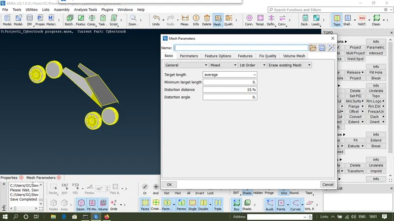
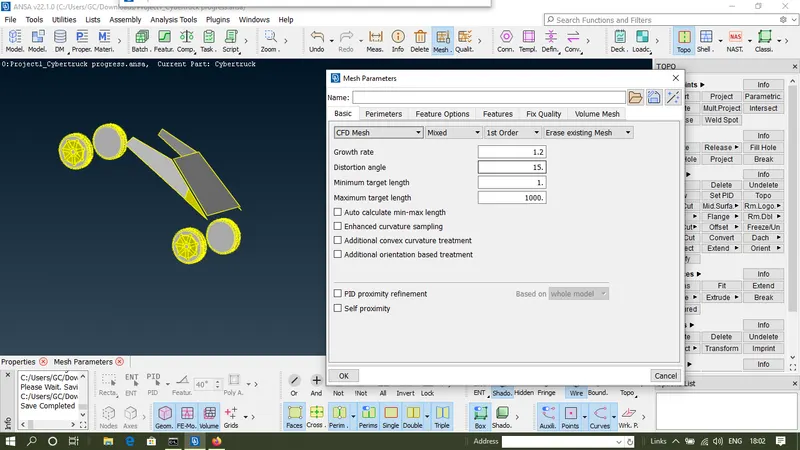
After performing the mesh in widow and tyres freeze these pids using freeze option by following the layout.
CLASSIC MESH > MACROS > FREEZE/UN > BOX SELECTION USING LEFT KEY.
Freezing of the pids are done because of diffrent target lengths present at the intersection of two PIDs.
> perform the meshing over the body of the car having the target length as 3mm.
classic mesh > perimeter > length > perimeter > box selection > assign target length as 3mm > macors > box selection > middle key > assign target length as 3mm > ok.
classic mesh > mesh generations > cfd > visible.
> If there are off elements then remove them by using the
RIGHT CLICK ON OFF ELEMENTS > IMPROVE > RESHAPE > SELECT EDGES > OK
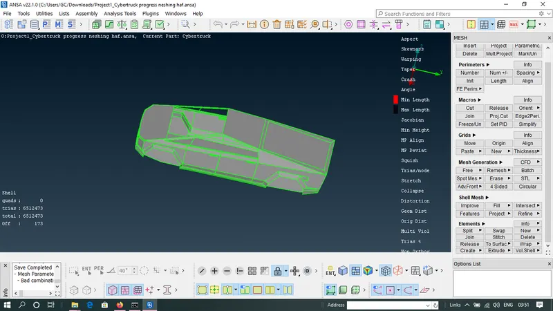
> After performing the improve options if there are still off elements are present and if present off elements are due to the maximum length then change the maximum length in Quality criteria and change maximum length from 3.5mm to 4mm. follow the layout
QUALITY CRITERIA > MAXIMUM LENGTH > CHANGE 3.5mm TO 4mm > APPLY >OK.
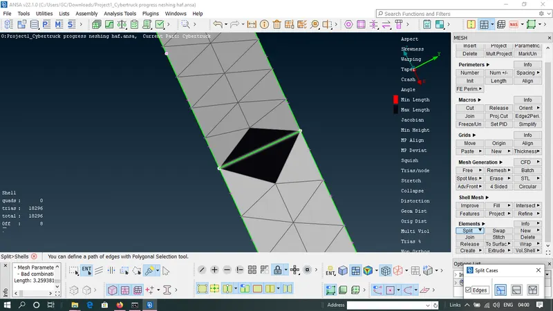
> After changing the maximum length as 4mm if there are still some off elements are present due to the maximum length then eliminate them manually by following the layout
classic mesh > elements > splits > select edges > middle key.
> check the dimension using MEASURE tool present at top of ANSA window.
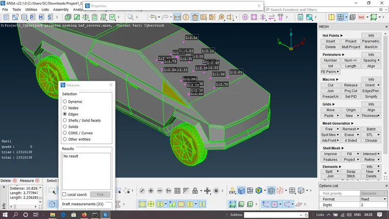
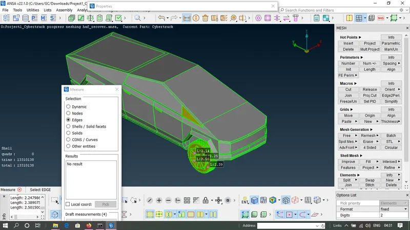
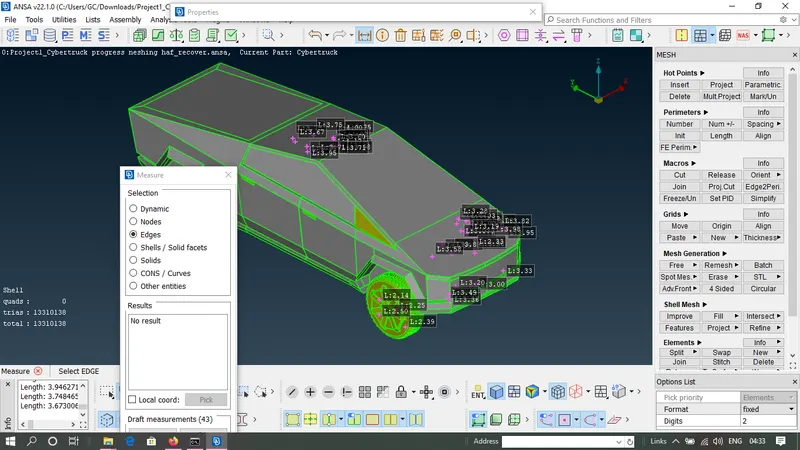
> Create the close contors of following dimensions.
> front domain of the close contour will be at a distance of 4 times of the length of the car from the car frontal portion that is at a distance of 23600mm as length of the car measured is 5900mm.
> rear domain of the close contour will be at a distance of 6 times of the length of the car from the car rear portion that is at a distance of 35400mm the large porion at the rear end due to the bake area and Negative pressure region present at back side of the car.
> Top domain of the close contour will be at a distance of 3 times of the height of the car from the car top portion that is at a distance of 5250mm.
> Bottom domain of the close contour will be at a distance of 650mm from the car bottom area.
> Both side domain of the close contour will be at a distance equal to width i,e, 1800mm from the car side portion i,e, extreme portion of optical side view mirror.
> create the close contour by following the steps.
1) Create the 3D points.
create the 3D points at a distance of 650mm from the bottom of the car, as the distace between car bottom area and tyres extreme oint at the base is 650mm.
TOPO > POINTS > RELATIVES > SELECT THE POINT AT THE BOTTOM OF THE CAR > MIDDLE KEY > ENTER DIRECTION AS dz =-1 > enter distance as 6500mm > ok.
By following this procedure a 3D points at 650mm below the bottom of the car will be created.
Create the 3D points at the front end of the car.
TOPO > POINTS > RELATIVES > SELECT THE 3D POINT > MIDDLE KEY > ENTER DIRECTION AS dy =-1 > enter distance as 23600mm( Length of the car as 5900mm+ four times the length of the car) > ok.
Create the 3d point at a approximate distance of 7650mm( height of the car as 1750+ 3 times the height of the car+ 650mm) from the 3D points those have been created.
create all the 3d points at rear end of the car by selecting the all foue 3d points and enter direction as dy = -1 and distance as 74900mm.
TOPO > POINTS > RELATIVES > SELECT THE ALL FOUR 3D POINTS > MIDDLE KEY > ENTER DIRECTION AS dY =1 > enter distance as 74900mm from the 3D points those are created at a distance of 23600 from the front portion of the car( length of the car as 5900+ 4 times the length of the car to the front portion of the car + six times the length of the car from the rear portion of the car ) from the 3D points those have been created > OK.
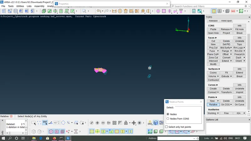
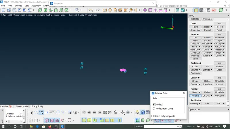
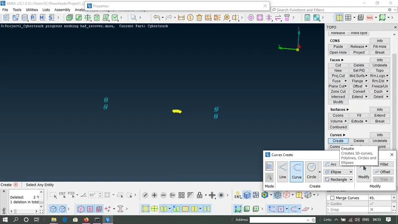
2) Create the curves/ edge for creating the surface between the 3D points.To create the edges follow the layout
TOPO > CURVES > CREATE > SELECT TWO 3d POINTS > PRESS MIDDLE KEY.
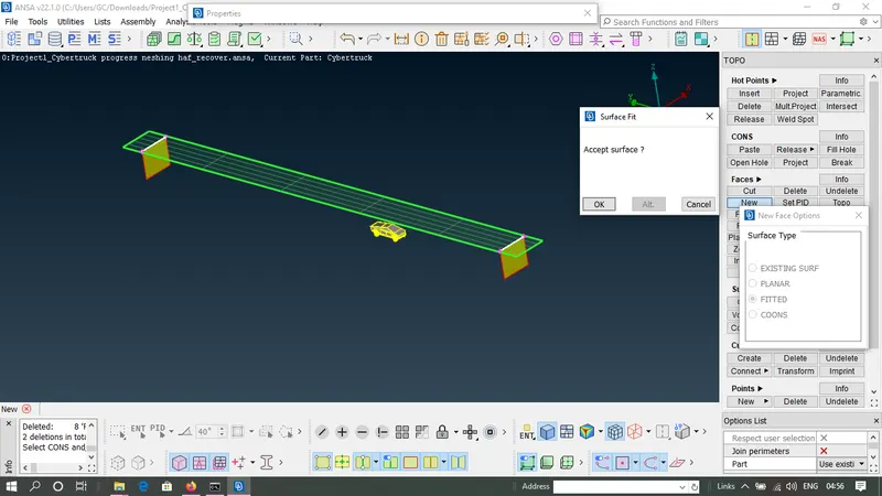
> Create the surface using the layout
TOPO > FACES > NEW > FITTED > SELECT EDGES > OK
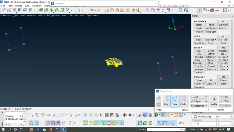
Delete the edges and 3D points using the universal delete option before deleting the 3D points and edges hide the surafce using boolen operator NOT and then select the 3D points using box selection and then delete them using using universal delete option.
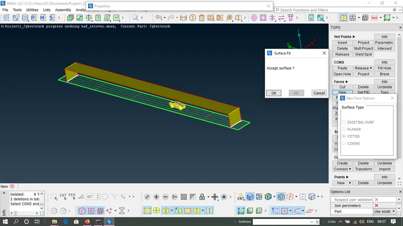
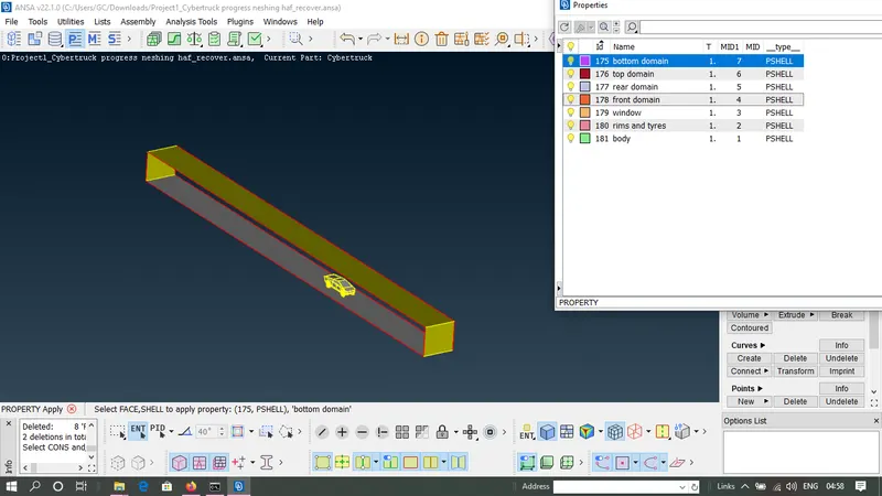
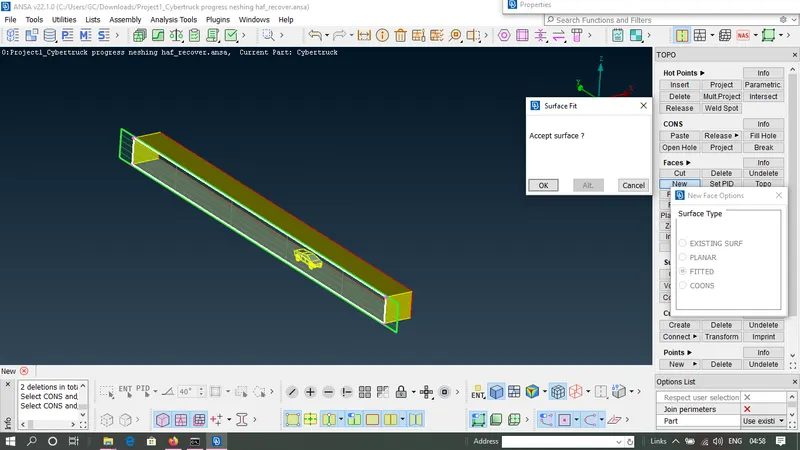
> Assign the target length as 20mm for the bottom domain and 100mm for the top domain of the close contour.
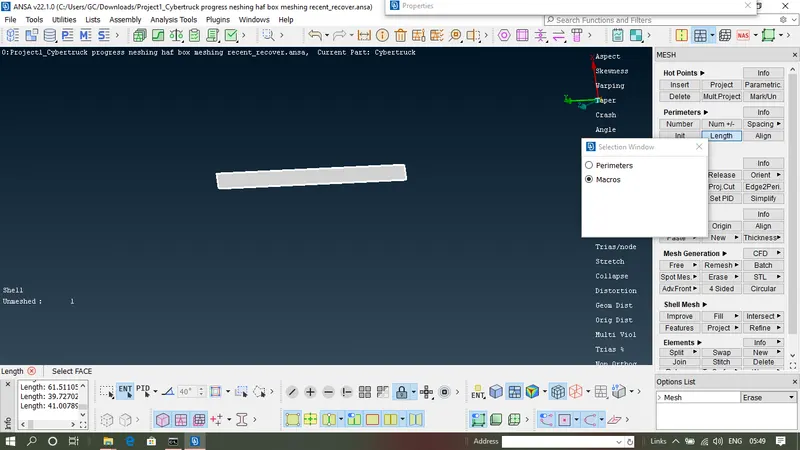
classic mesh > perimeter > length > perimeter > box selection of the bottom domain by hiding all other pids using bulb button > assign target length as 20mm > macors > box selection > middle key > assign target length as 20mm > ok.
classic mesh > perimeter > length > perimeter > box selection of the Top domain by hiding all other pids using bulb button > assign target length as 100mm > macors > box selection > middle key > assign target length as 100mm > ok.
> Use spacing option, for gradually increasing the mesh element size from 20mm to 100 mm spacing option is used.
CLASSIC MESH > PERIMETERS > SPACING > SELECT Bi- Geometric as biasing > start factor as 1.1 > dstart as 20mm > dlimit as 100mm > select at the bottom portion at the cons present at all four edges near the bottom domain of the close contour for deciding the direction for gradual increase in the mesh element size.
> perform meshing over the surfaces by hiding the car body using the bulb window present at the pid manager.
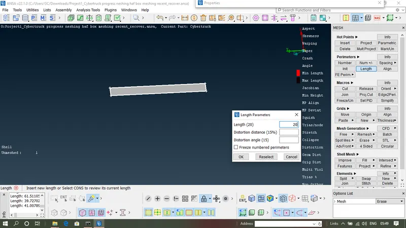
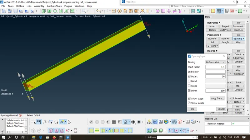
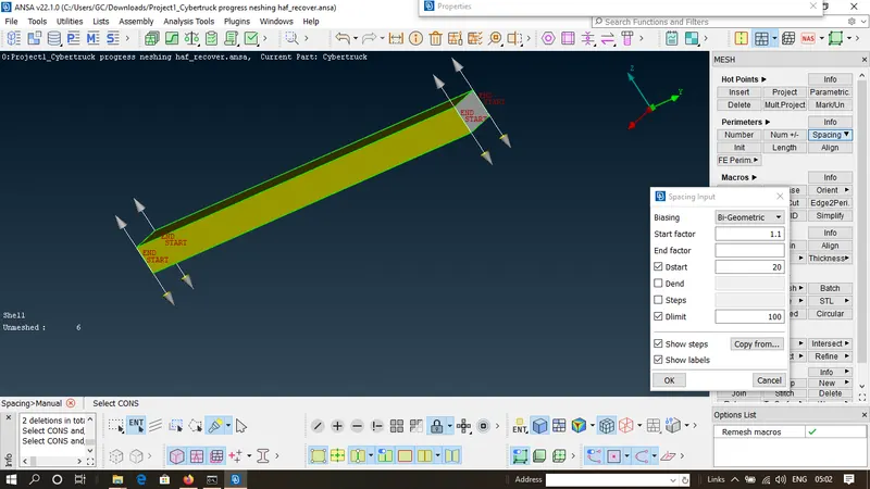
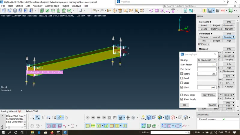
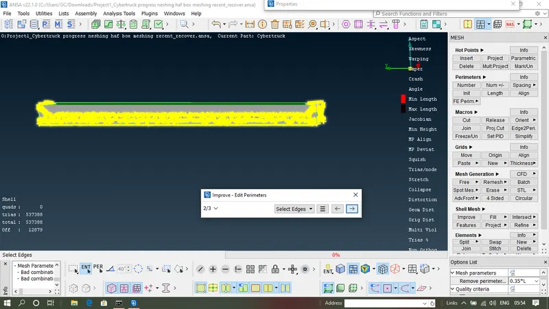
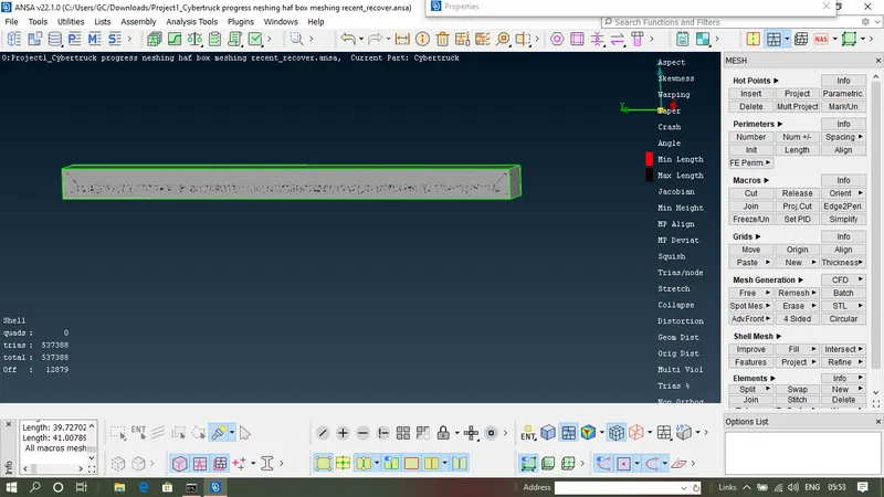
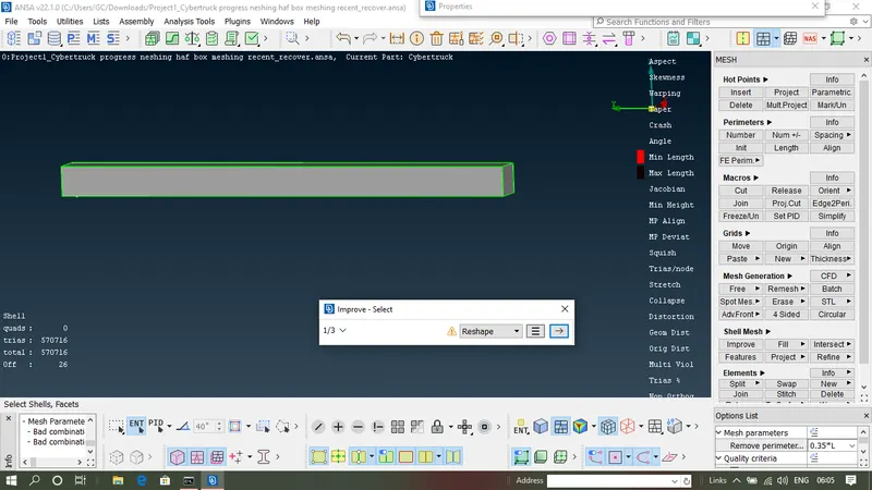
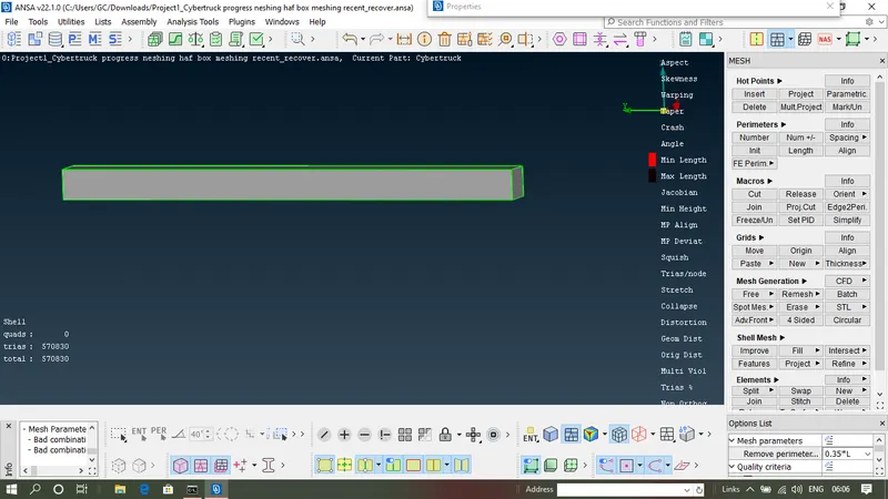
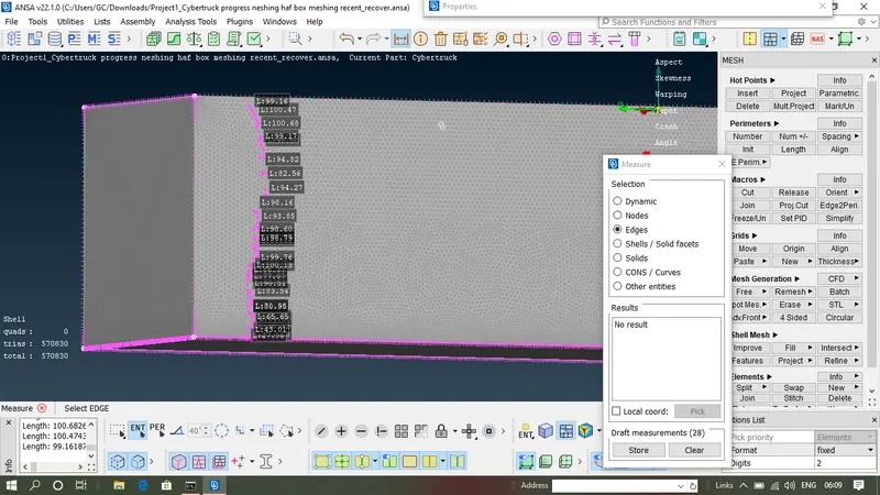
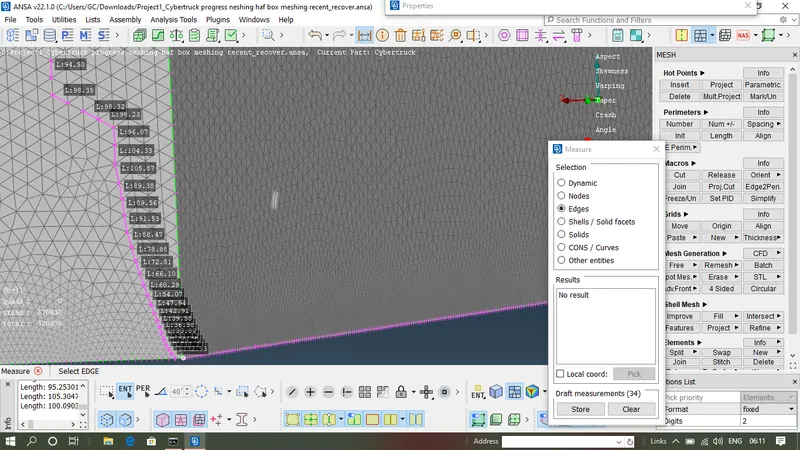
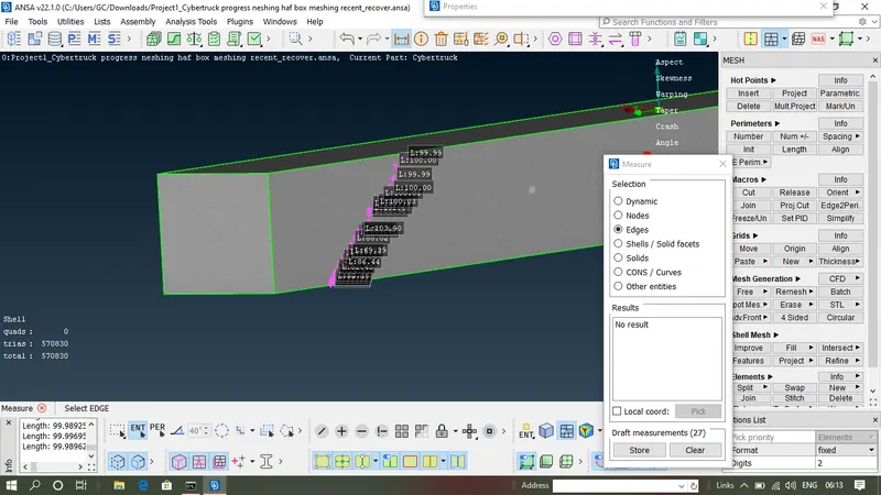
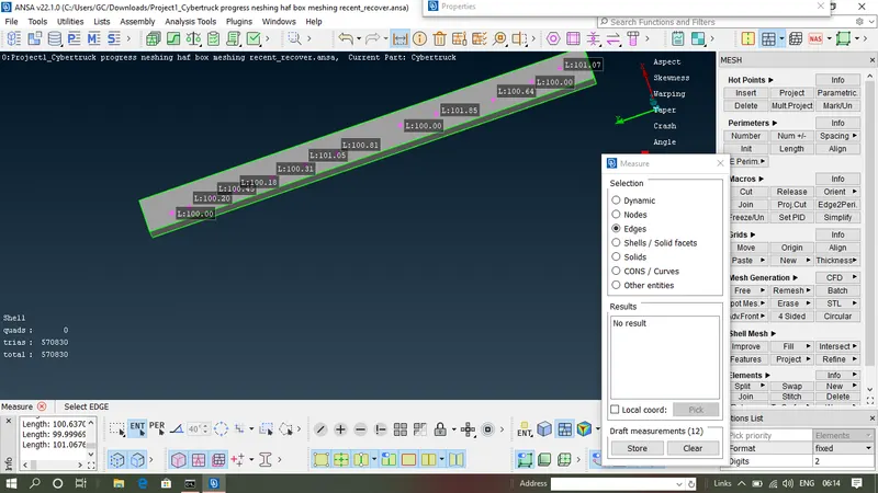
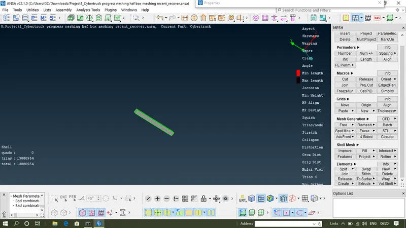
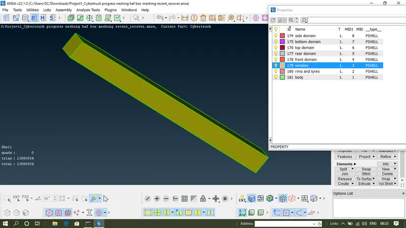
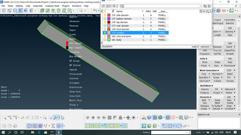
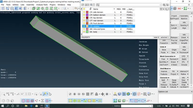
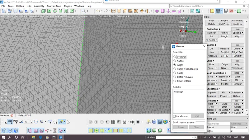
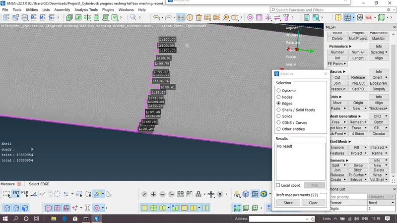
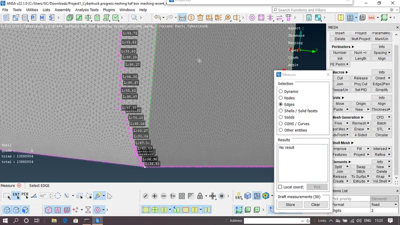
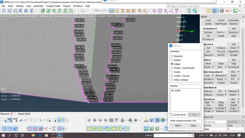
So in the above image it is clear that mesh element size is gradually increasing from 20mm to 100mm from bottom to top domain of the close contour and have zero off elements.