Week 6 - CHT Analysis on a Graphics card
AIM: CONJUGATE HEAT TRANSFER ANALYSIS ON A GRAPHICS CARD
PROBLEM STATEMENT:
Perform a steady-state conjugate heat transfer analysis on a model of a graphics card. You can use appropriate materials of your choice for the simulation. Make sure to properly define the correct solid and fluid zones. Refer the video for further clarification and the model is provided below the video.
Run the simulation for best possible mesh with combination of coarse and refined mesh in different regions. Explain the reason for choosing the particular mesh settings.
Your Objectives:
- Run the simulation by varying the velocity from 1m/sec to 5m/sec for at least 3 velocities and discuss the results.
- Find out the maximum temperature and heat transfer coefficient attained by the processor.
- Prove that the simulation has achieved convergence with appropriate images and plots.
- Identify potential hotspots on the model.
The Conjugate Heat Transfer (CHT) analysis type allows for the simulation of heat transfer between solid and fluid domains by exchanging thermal energy at the interfaces between them. Typical applications of this analysis type exist as, but are not limited to, the simulation of heat exchangers, cooling of electronic equipment, and general-purpose cooling and heating system.
The term conjugate heat transfer can be used to describe the processes which involve a temperature variation within the solids and fluids themselves due to the thermal interaction between the solid and the fluid.
During CHT the heat transfer can take place from solid media to the fluid media and vice-versa. This is because fluids flow around solids or between solid walls, and also the solids are mostly immersed in a fluid.CHT analysis is beneficial in engineering applications because it shows the heat exchanging capabilities between the two surfaces in the engineering device and various optimization can be done to improve the thermal characteristics of the devices.
Thus, this can be used to improve the heat transfer rate wherever required. It also helps us to identify the key parameters that enhance the fluid flow and heat transfer within the system. Conjugate heat transfer corresponds with the combination of heat transfer in solid and fluid. In solids, conduction often dominates, whereas, in fluids, convection dominates. Efficiently combining heat transfer in fluids and solids is the key to designing effective coolers, heaters, or heat exchangers. Forced convection is the most common way to achieve a high heat transfer rate. In some other applications, the performance is further improved by combining convection with phase change.CHT can be performed to improve the cooling performance of water jackets and increase engine life.
To have analytical or numerical prediction of heat transfer coefficient close to experimentally obtained values, one must focus on conjugating the boundary condition at the fluid–solid interface through coupled heat transfer analysis. Such a coupled field study is termed as Conjugate Heat Transfer (CHT) . However it may be noted that Coupled field analysis is not just limited to CHT studies involving fluidand solid domains. Coupled field analysis or specifically CHT analysis is essential in a situation where solution domainconsists of more than one sub-domains in which heat transfer is governed by different differential equations. In such a case suitable governing equations are to be solved in the respective sub-domains and these solutions need to be conjugated at the interfaces of sub-domains. Aforesaid explicit solution seeking and coupling are also inevitable even if the heat transfer is governed by same setof differential equations, but sub-domains are having dissimilar material properties.
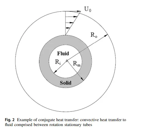
for conjugate heat transfer situation is depicted in Fig. 2. In this case, there is an external tube of outer radius R0, which is heated to a constant wall temperature of 700 K and rotates at constant angular velocity. A fluid field is kept between this rotating tube and a internal stationary hollow cylinder. The internal stationary cylinder is uniformly heated by a hot fluid flowing inside the stationary cylinder. This is a highly conjugated heat transfer situation where two different flow streams and one separate solid domain need to be solved simultaneously to get final solution. This heat transfer setup is very similar to the case of internal cooling of a gas turbine blade.
Advantges:
1. The Conjugate Heat Transfer setup replaces the empirical relation of proportionality of heat flux to temperature difference with heat transfer coefficient. The wall heat transfer coefficients & their local variations are directly computed within the model and do not involve the solving of complex empirical relations. Thus the simulations are carried out much faster.
2. As long as the boundary conditions are accurately defined, the solutions are highly accurate due to the simplicity of the CHT model.
3. There is no limit for the number of surfaces and hence can be applied for a large number of regions in a given assembly.
4. Since the CHT model is a combination of the heat transfers in both a solid & fluid model, it can be applied for all combinations of interactions (i.e. Solid - Fluid interaction, Solid - Solid interaction and Fluid - Fluid interaction)
2) Application of CHT Analysis
CHT analysis is used in various applications to understand the heat transfer between two domains (solid and water or for more than two sub-domain). Some example:-
1. Heat transfer analysis in the cooled turbine blade Wang.
2. Measurement of the heat transfer coefficient in a Channel with Pin Fins.
3. Analysis of a Thermocouple Sensor in a Low-Temperature Nitrogen Gas Ambient.
4. Analysis of Natural Convection and Radiation Heat Transfer from Various Shaped Thin Fin-Arrays Placed on a Horizontal Plate.
5. Conjugate heat transfer and coupled field analysis is aerospace engineering.
6. Conjugate-Heat-Transfer Immersed Boundary Method for Turbine Cooling.
7. Thermal Treatment of Materials.
> MODE OF HEAT TRANSFER:
CONDUCTION:
Conduction is a mode of heat transfer which generally occurs in solid due to temperature diffrence associated with molecular lattice vibrational energy transfer and also by free electron transfer. The reason behind
all electrically good conductors are also in general good conductors of heat is that the presence of abundant number of free electrons.
Example: ALL METALS
FOURIER LAW OF CONDUCTION:
The law states that the rate of heat transfer by conduction along a given direction is directly proportional to the temperature gradient along that direction and is also directly proportional to the area of heat transfer lying perpendicular to the direction of heat transfer.
CONVECTION:
Convection is a mode of heat transfer which generally occurs between a solid body and the surrounding fliud due to temperature diffrence associated with macroscopic bulk motion of fluid transporting thermal energy.( in the form of enthalpy).
Due to the fluid motion, there are three contributions to the heat transfer:
1. Convective contribution: Depending on the properties of the fluid and its region of flow, the domination of conduction and convection varies.
2. Viscous effects: Due to the fluid flow, the viscosity creates heat. This effect is often neglected due to its negligible value but should be taken into account for high-velocity cases.
3. Density effects: When the density becomes related to the temperature, the domain will have different densities at different locations based on the temperature distribution. This variation in density can cause the compression which in-turn generates the heat.
NEWTONS LAW OF COOLING:
The law states that the rate of heat transfer by convection between a solid body and the surronding fluid is directly proportional to the temperature diffrence between them and is also directly proportional to the area of contact between them.
RADIATION:
Radiation is the mode of heat transfer which does not reqiure any material medium for its propagation and hence occurs by electro magnetic wave propagation travelling with the speed of light.
Radiation mode of heat transfer compltely predominates over conduction and convection particularly when the temperature diffrence is sufficientle large.
STEFAN BOLTZMAN LAW:
The law states that the radiation energy emiited from the surface of a black body per unit time per unit area is directly proportional to the fourth power of the absolute temperature of black body.
FINS:
Fins are projection protrouding from the hot surafce in to ambient fluid atmospheric air and they are meant for increasing the heat transfer rate by increasing surafce area of heat transfer.It is a conduction convection system employed to dissipiate heat from a surface at a faster rate to the surrounding fluid.
Example:
> Air cooled internal combustion engine.
> Reciprocating Air compressor/ positive displacement type of compressor
> Electric motors and transformers
> Electronic devices
> Automobile Radiator
NOTE: Fins are always used only when the convective heat transfer coefficient are relatively low i,e, with atmospheric air.
CHT ANALYSIS ON GRAPHICS CARD:
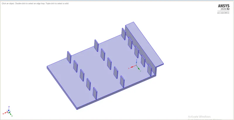
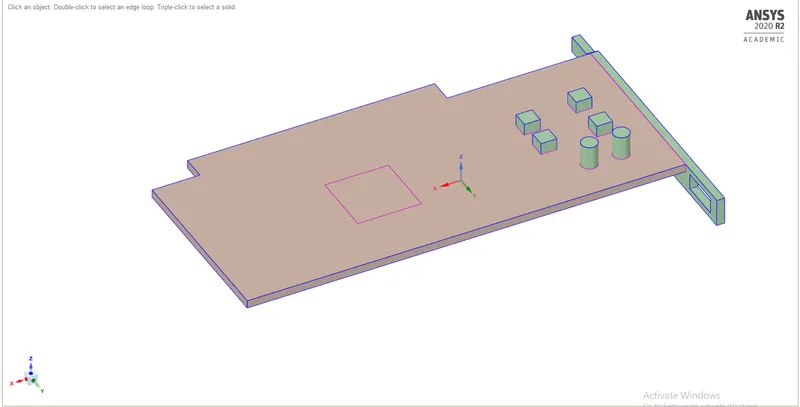
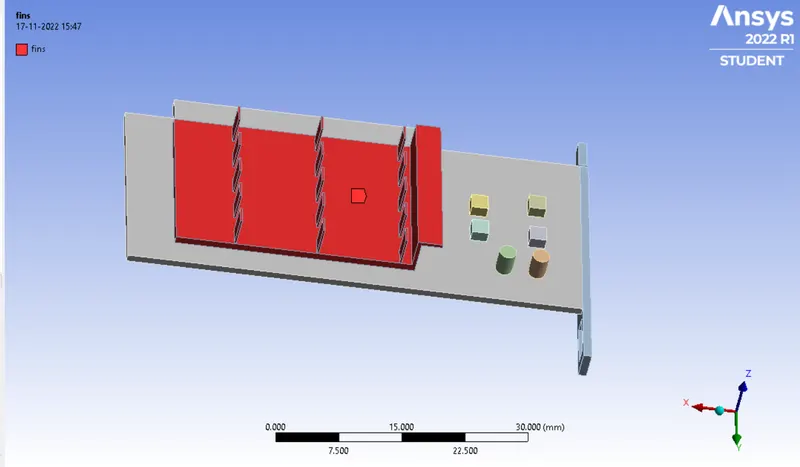
All the heat is generated in the processor so for cooling the surface here diffrent fins are present at the top of the processor.Heat is generated at the processor it will conducted throughout the fins the whole purpose of adding the fins here to increse the surafce area, hence when air will pass over the fins it will going to get cooled so due to which we can operate a processor at optimum temperature.
PROCEDURE:
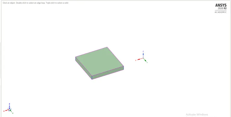
GEOMETRY:
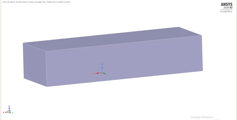
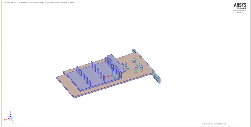
> IMPORT THE GEOMETRY FROM THE SPACE WHERE THE GEOMTERY HAS SAVED USED FILE MENU PRESENT AT TOP LEFT CORNER OF THE SCREEN.
> For obtaining the conformal mesh at the interface use "Share" option present at the workbench window.
MESHING:
CASE 1:
> Create the meshing with default element size of 10.829mm.
> create the meshing with default mesh size to all the parts of the given geometry.
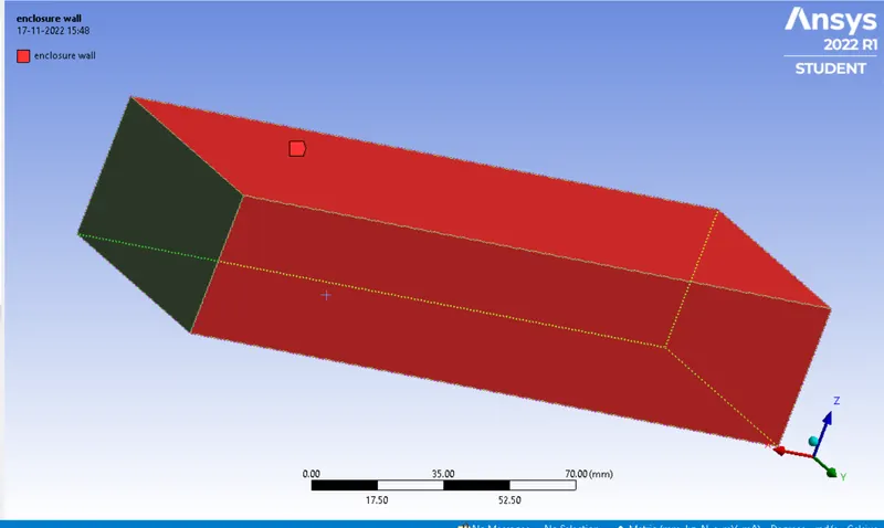
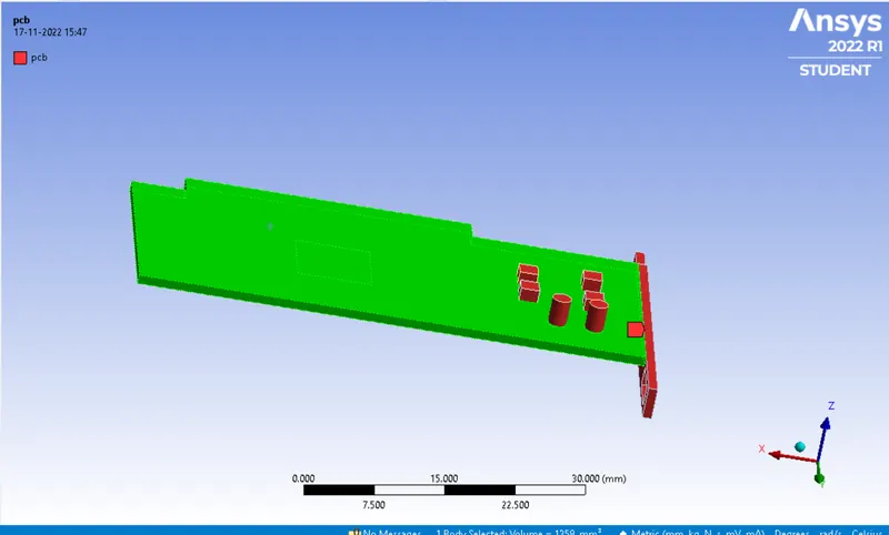
> Perform the name selection for diffrent parts of the geometry.
> Enclosure wall
> PCB
> fins
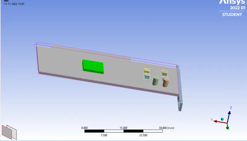
> processor
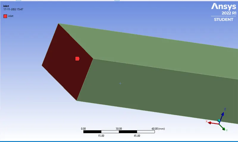
> inlet
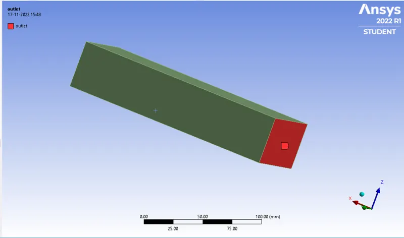
> outlet
> The final mesh will be look like as showm in the below image with total number of mesh elements are 54068.
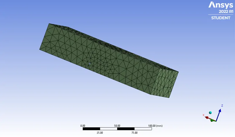
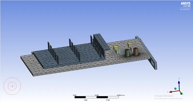
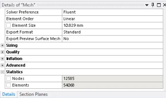
> Total number of mesh elements are 54068.
SETUP:
CASE 1.1: In this case use default element size of 10.829mm with inlet velocity of 5m/s.
| SOLVER TYPE | PRESSURE BASED |
| SOLVER TIME | STEADY STATE |
| ENERGY | ON |
| VISCOUS MODEL | K-EPSILON |
| MATERIALS |
PCB - POLYSTYRENE PROCESSOR - SILICON FINS - ALUMINIUM |
| CELL ZONES | Assiginig the diifrent material and type of material for diiffent zones of the geometry. |
| SOURCE TERM | ON (PROCESSOR USED AS SOURCE TERM WITH HEAT GENERATION OF 31250000 W/m^3 |
| BOUNDARY CONDITIONS |
INLET - VELOCITY INLET WITH VELOCITY OF 5M/S AND TEMPERATURE IS 300K. OUTLET - PRESSURE OUTLET WITH ATMOSPHERIC CNDITIONS |
| METHOD | COUPLED |
| NO. OF ELEMENTS | 54068 |
> Open the geometry in the setup.
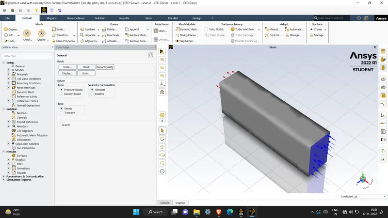
> Disable the inlet, outlet and enclosure from the domain windiw so that we can able to see the interior parts.
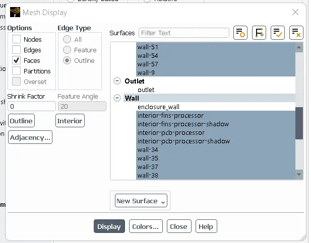
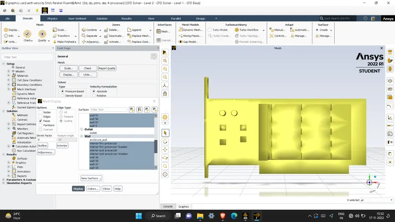
> solver type as pressure
> solver time as stedy state
> velocity formulation as absolute

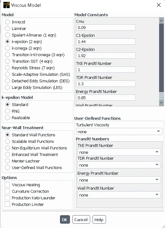
> Enable energy and set viscous model as k-epsilon,standard,standard wall functions.
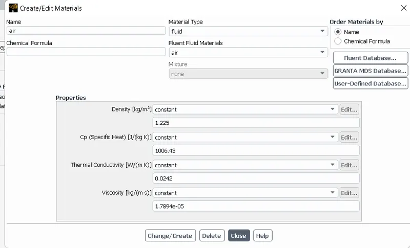
Assign the material for diffrent parts of the geometry also assign the suitable material for the diffrent parts of the geometry by creating them in the fluent database.
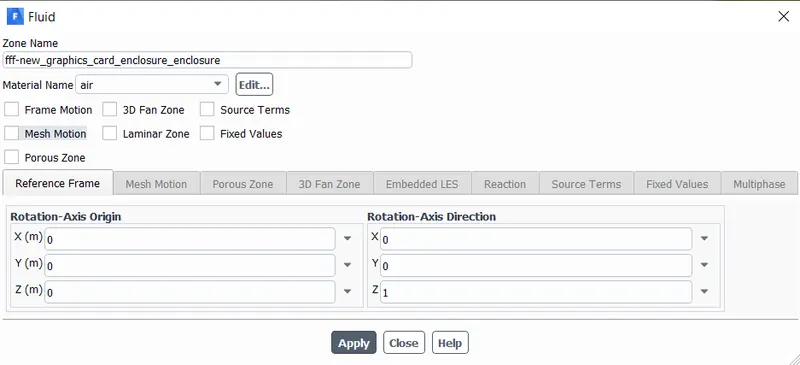
Enclosure wall- air
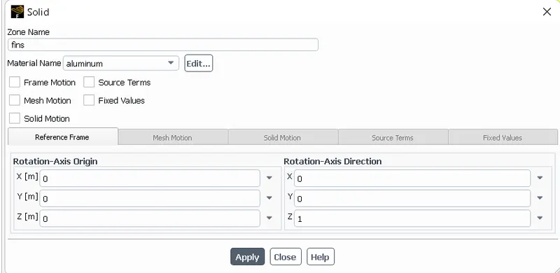
For fins use material as Aluminium because it has greater value of thermal conductivity due to which it is good conductor of heat.
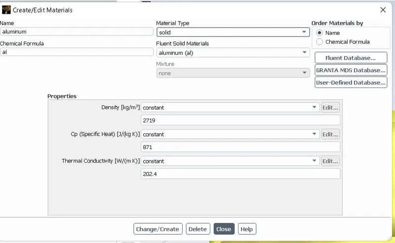
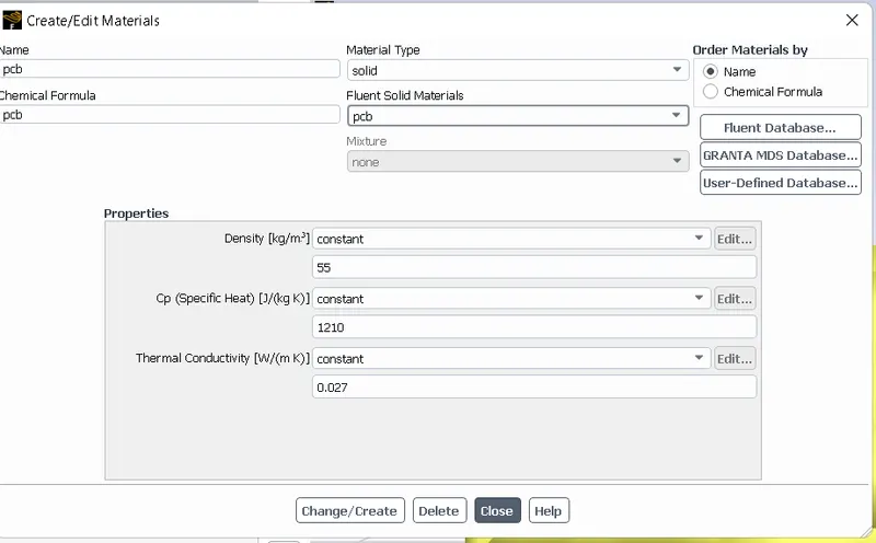
For pcb create the material which has properties as same as polystyrene.
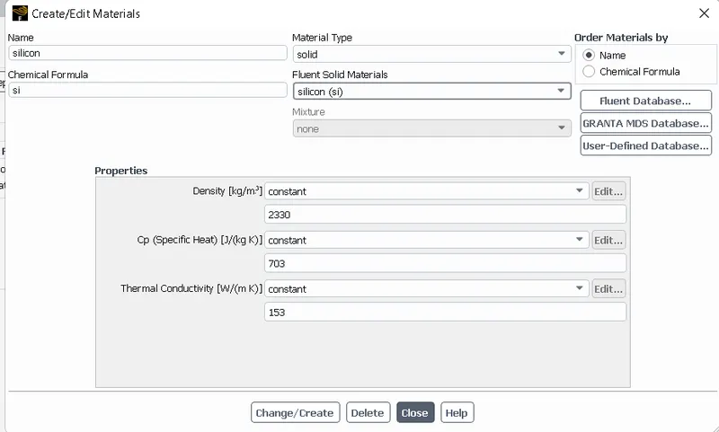
For processor create the material silicon. Silicon is used as material for the processor because as in the problem statement it is mentioned that the processor will act as heat source so for as silicon has highier calue thernal conductivity and low specific heat so it will conduct more heat and store lee heat due to which in this case silicon is used as material for the processor.
CELL ZONES CONDITIONS:
> Go to cell zones condition and assign the material for the diffrent zones of the geometry.
Heat generation condition will be setup from the cell zones conditions where under the processor zone while after assigning the material for the processor zone Enable source terms and give heat generated value there. So in this case processor will work as source and generates heat and dissipiate it in to the fins and other parts of the graphics card.
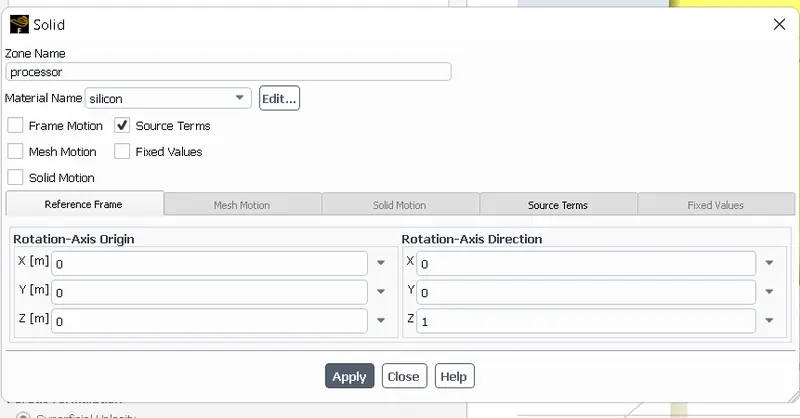
In this case we have assume less value of heat transfer rate for the processor i,e, 2 watt because size of processor is very small.
The processor is assumed as the only source of heat. The heat generated by the processor is calculated as:-
Setting up the source terms :
For this case we consider that, our processor is a source terms and it generating heat.
So, for setting up the source term go to Zones - Cell zones - and click on the processor for editing which is in the Solid.
After that select the material to silicon and click on the source terms to enabled it and set the energy source to 1.
Graphics Card Power = 2W
Volume of the card = 8 x 8 x 1
= 64mm3=64e-9m3">64mm3=64e−9m^3
Heat Generated = heat tranfer rate/ volume of processor
31250000 W

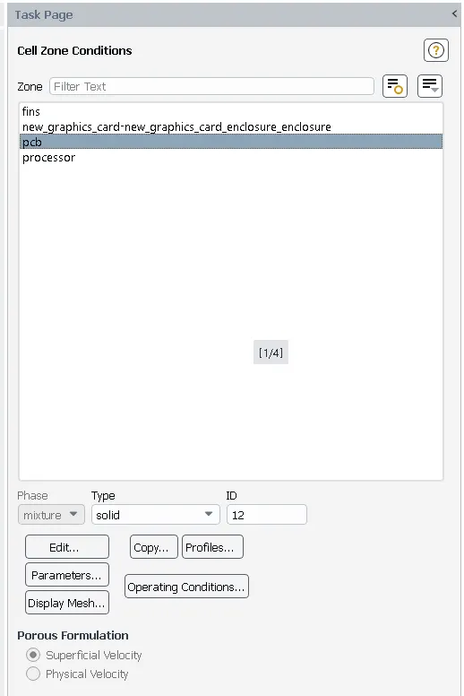
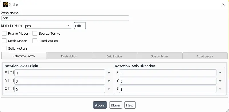
> for pcb material type as solid
> for fins material tyoe as solid
> for air material type as fluid
> Assign the boundary conditions
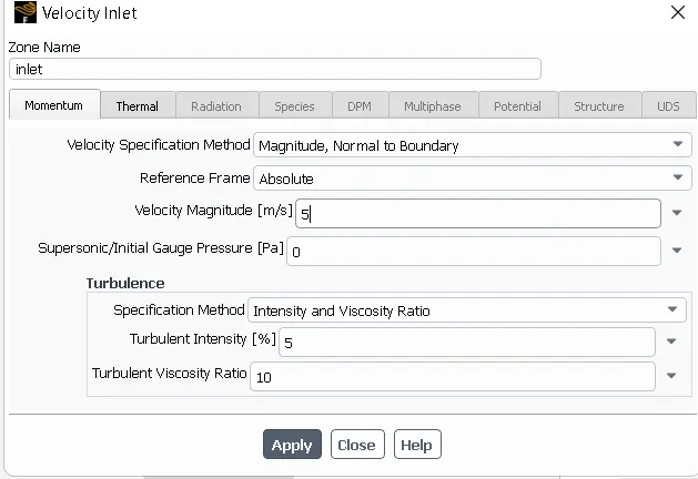
> INLET:
Type: Velocity Inlet
Velocity: 5m/s
Temperature: 300 K
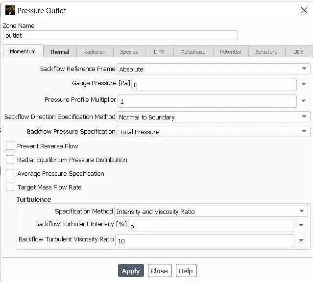
> OUTLET:
Type: Pressure Outlet
Pressure: 0 Pa(Gauge Pressure)
Temperature: 300K
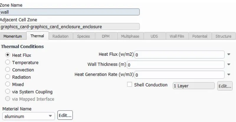
Symmetry: Symmetry
Wall: Wall
RESULTS:
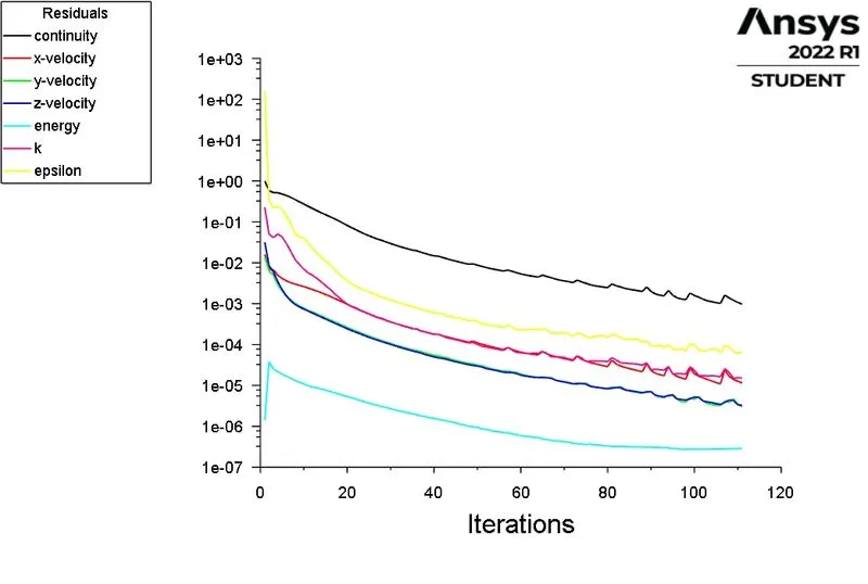
> SCALED RESIDUALS:
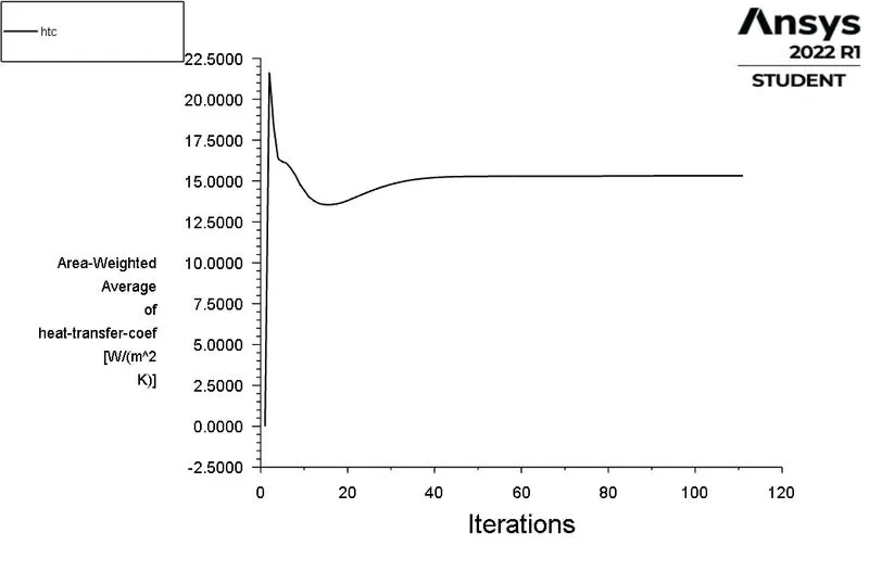
> HEAT TRANSFER COEFFICIENT:
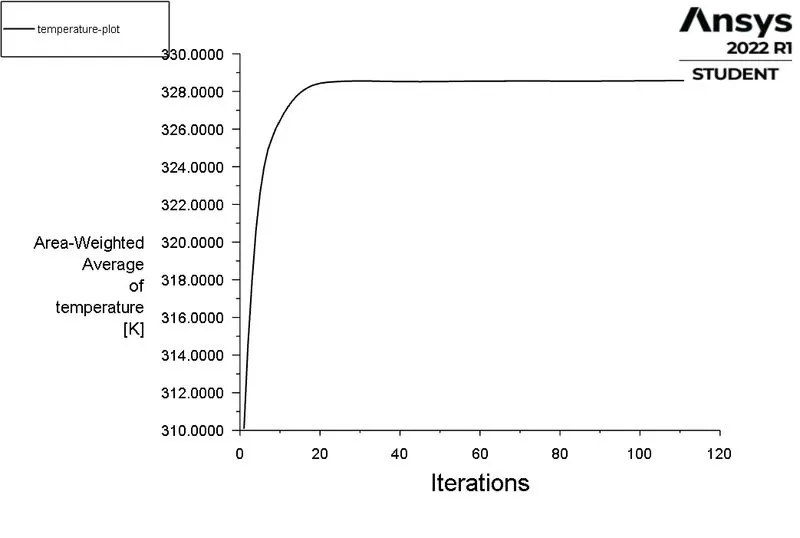
> TEMPERATURE:

POSTPROCESSING:
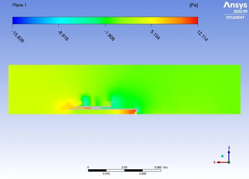
PRESSURE CONTOUR:
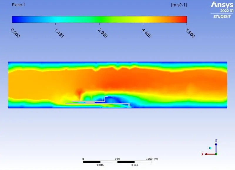
VELOCITY CONTOUR:
TEMPERATURE CONTOUR:
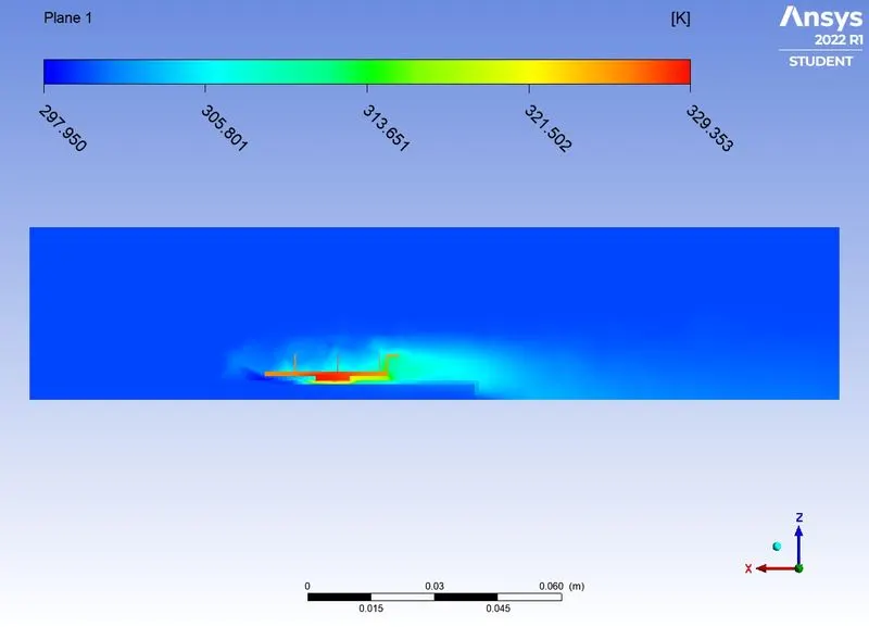
TEMPERATURE CONTOUR:
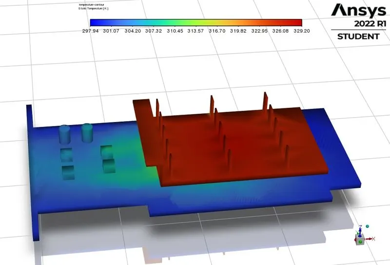
TEMPERATURE CONTOUR AT PROCESSOR:
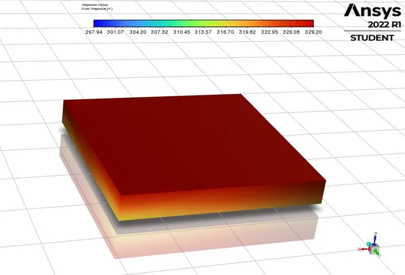
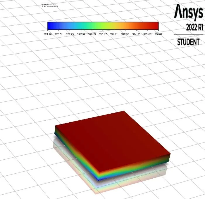
TEMPERATURE CONTOUR AT PROCESSOR WALL:
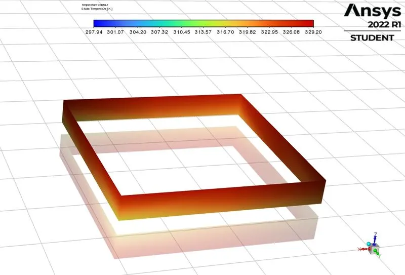
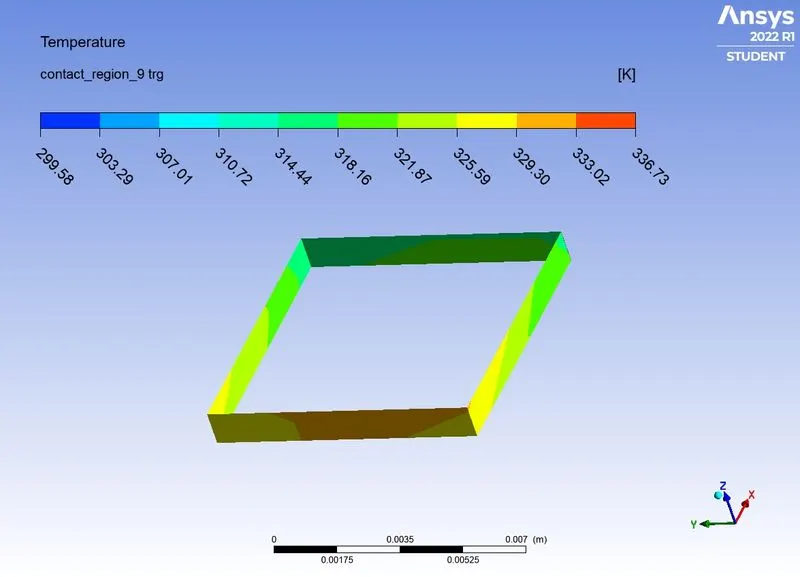
TEMPERATURE CONTOUR AT PROCESSOR AND FINS INTERFACE:
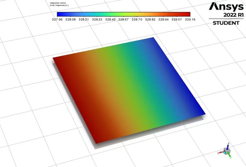
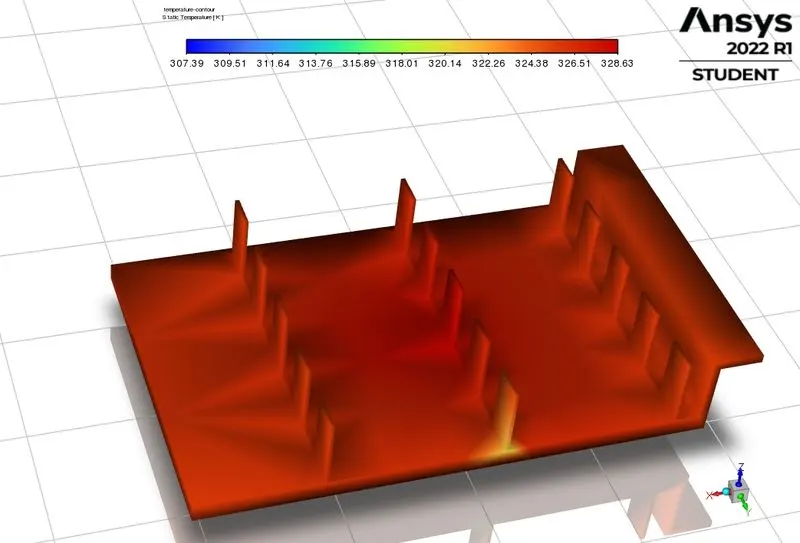
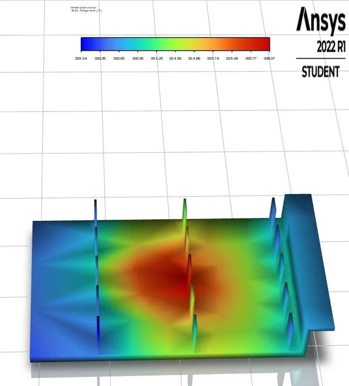
TEMPERATURE CONTOUR AT FINS:
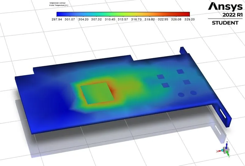
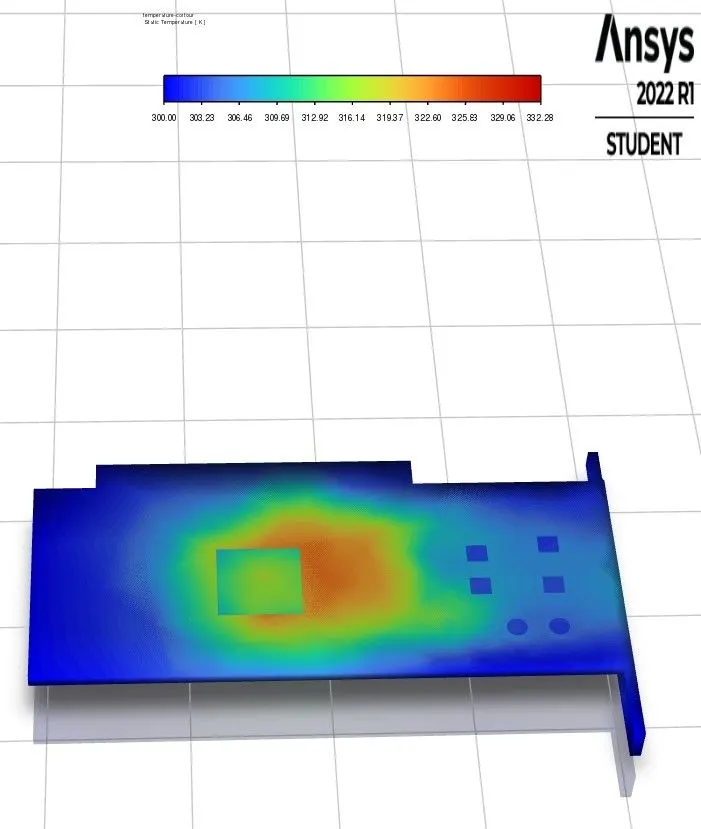
TEMPERATURE CONTOUR AT PCB:
HEAT TRANSFER COEFFICIENT CONTOUR:
HEAT TRANSFER COEFFICIENT CONTOUR AT PROCESSOR WALL EXPOSED TO AIR:
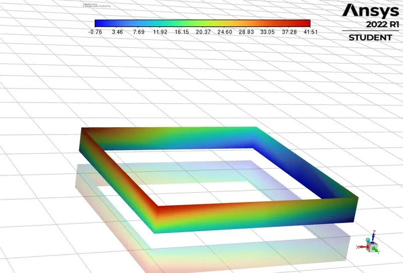
CASE 1.2 : COARSE MESH WITH DEFAULT MESH SIZE OF 10.829 mm WITH INLET VELOCITY OF 3m/s.
| SOLVER TYPE | PRESSURE BASED |
| SOLVER TIME | STEADY STATE |
| ENERGY | ON |
| VISCOUS MODEL | K-EPSILON |
| MATERIALS |
PCB - POLYSTYRENE PROCESSOR - SILICON FINS - ALUMINIUM |
| CELL ZONES | Assiginig the diifrent material and type of material for diiffent zones of the geometry. |
| SOURCE TERM | ON (PROCESSOR USED AS SOURCE TERM WITH HEAT GENERATION OF 31250000 W/m^3 |
| BOUNDARY CONDITIONS |
INLET - VELOCITY INLET WITH VELOCITY OF 3M/S AND TEMPERATURE IS 300K. OUTLET - PRESSURE OUTLET WITH ATMOSPHERIC CNDITIONS |
| METHOD | COUPLED |
| NO. OF ELEMENTS | 54068 |
RESULTS:
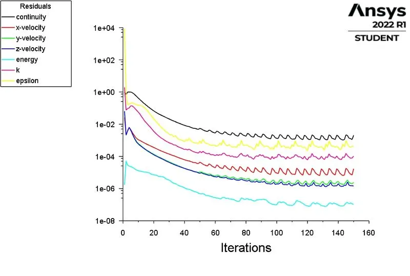
> SCALED RESIDUAL :
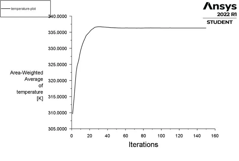
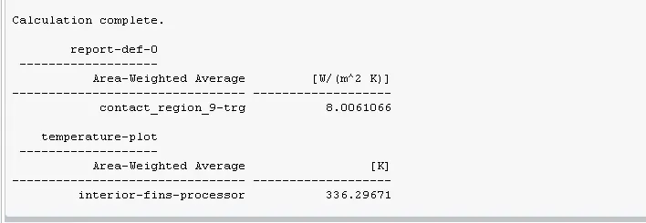
> TEPERATURE PLOT:
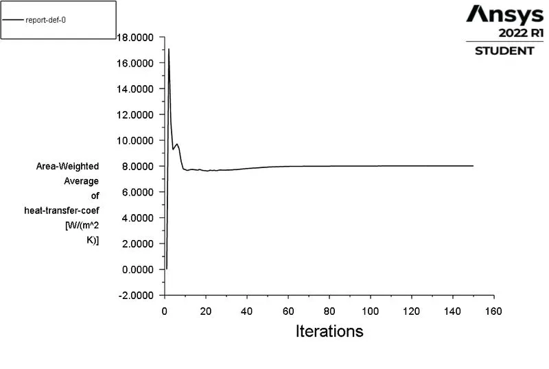
> HEAT TRANSFER COEFFICIENT PLOT:
> POST PROCESSING;
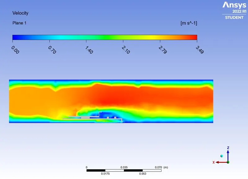
> VELOCITY CONTOUR:
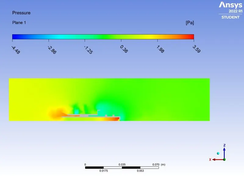
> PRESSURE CONTOUR :
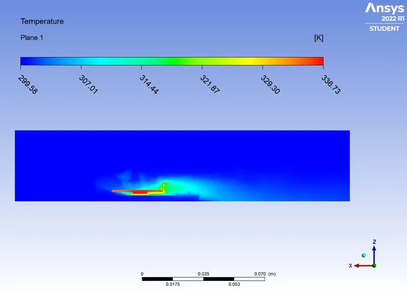
> TEMPERATURE CONTOUR:
> TEMPERATURE CONTOUR FOR FINS:
> TEMPERATURE CONTOUR FOR PCB:
> TEMPERATURE CONTOUR FOR PROCESSOR WALL:
> HEAT TRANSFER COEFFICIENT CONTOUR:
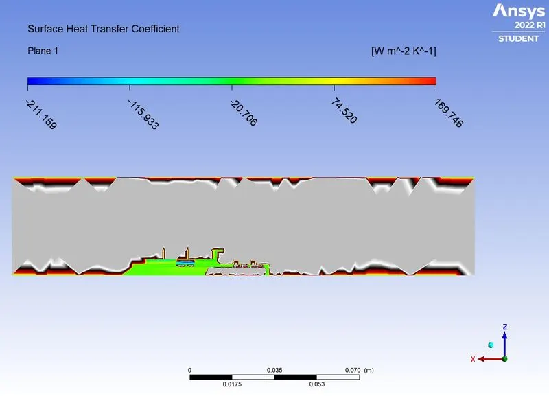
> HEAT TREANSFER COEFFICIENT AT PROCESSOR WALL:
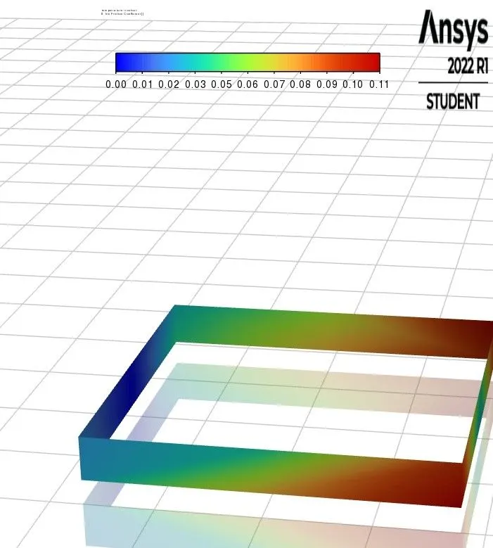
CASE 1.3: COARSE MESH WITH DEFAULT MESH SIZE OF 10.829mm with velocity of 1m/s.
| SOLVER TYPE | PRESSURE BASED |
| SOLVER TIME | STEADY STATE |
| ENERGY | ON |
| VISCOUS MODEL | K-EPSILON |
| MATERIALS |
PCB - POLYSTYRENE PROCESSOR - SILICON FINS - ALUMINIUM |
| CELL ZONES | Assiginig the diifrent material and type of material for diiffent zones of the geometry. |
| SOURCE TERM | ON (PROCESSOR USED AS SOURCE TERM WITH HEAT GENERATION OF 31250000 W/m^3 |
| BOUNDARY CONDITIONS |
INLET - VELOCITY INLET WITH VELOCITY OF 1M/S AND TEMPERATURE IS 300K. OUTLET - PRESSURE OUTLET WITH ATMOSPHERIC CNDITIONS |
| METHOD | COUPLED |
| NO. OF ELEMENTS | 54068 |
RESULTS:
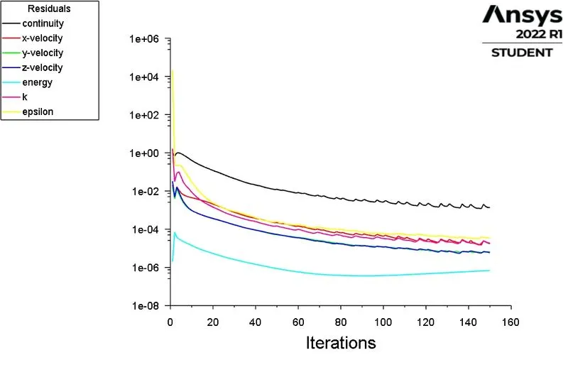
> SCALED RESIDUAL :
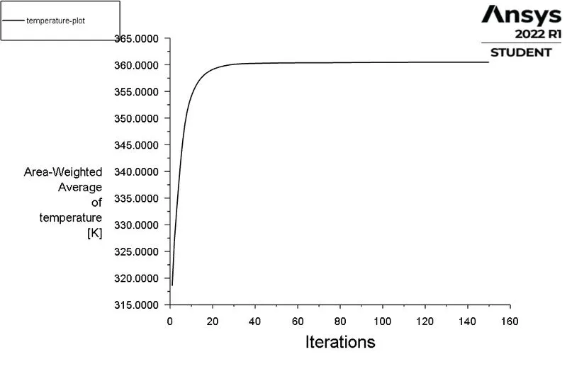
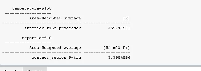
> TEPERATURE PLOT:
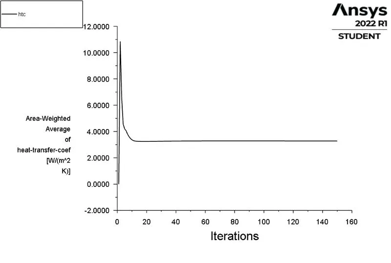
> HEAT TRANSFER COEFFICIENT PLOT:
> POST PROCESSING;
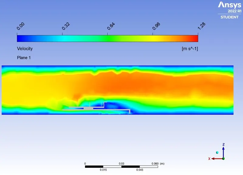
> VELOCITY CONTOUR:
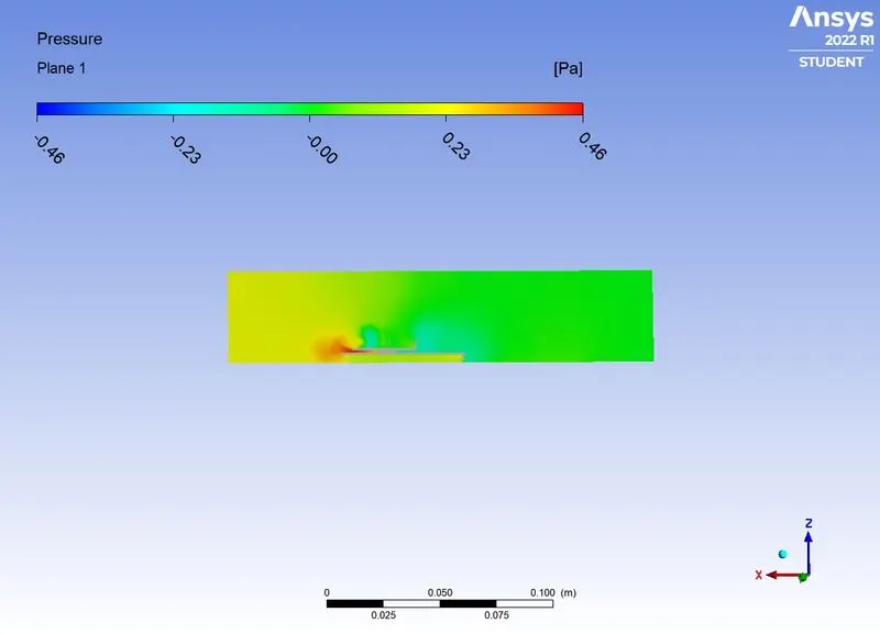
> PRESSURE CONTOUR :
> TEMPERATURE CONTOUR:
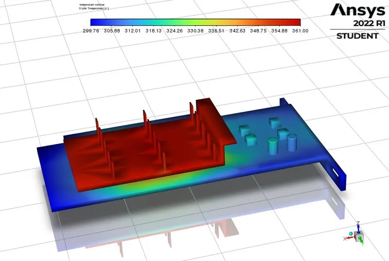
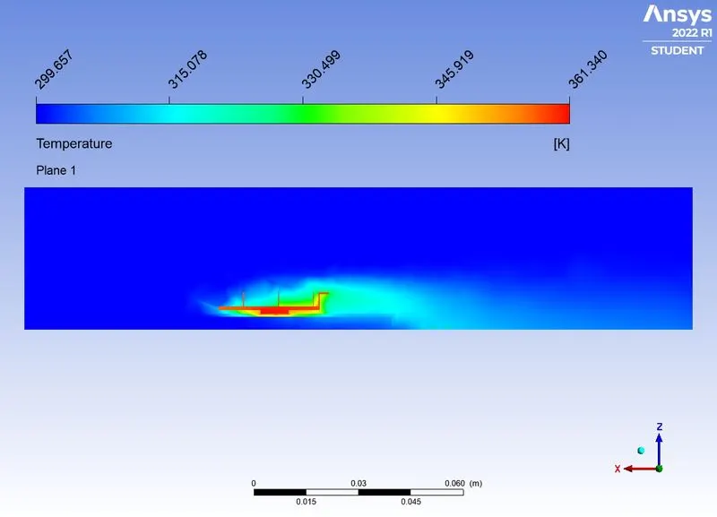
> TEMPERATURE CONTOUR AT XZ PLANE:
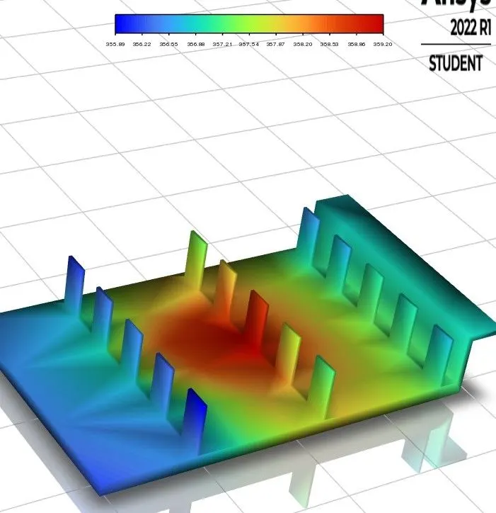
> TEMPERATURE CONTOUR FOR FINS:
> TEMPERATURE CONTOUR FOR PCB:
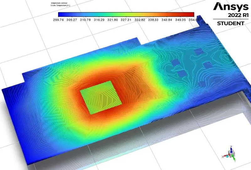
> TEMPERATURE CONTOUR FOR PROCESSOR WALL:
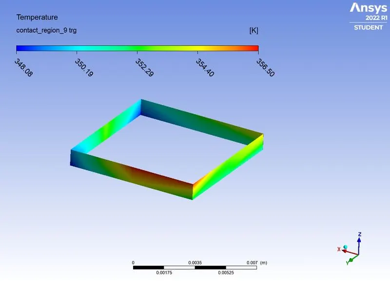
> HEAT TREANSFER COEFFICIENT AT PROCESSOR WALL:
CASE 2: FINE MESH WITH OUTER ENCLOSURE HAS MESH SIZE OF 8mm AND INNER PARTS HAVE MESH SIZE OF 1mm.
MESHING:
| enclosure wall | 8mm |
| fins | 1mm |
| processor | 1mm |
| pcb | 1mm |
We are more interested in the thermal energy transfer from Microprocessor to Aluminium fin where it cools with airflow and this is where our turbulence model also plays a vital role, well there's not much of difference in its varietals, but this tells us how heat transfer takes place and this is the only 2 body in the GPU where the temperature is at highest, and we can see that in out BASE MESH fin and microprocessor CFD-post results.
That's why we refine these 2 whole bodies alone where we can exact results in simulation. In Base mesh, the results may not be viewed accurately as the mesh is too coarse not only around 2 Hotspot bodies but the GPU as a whole.
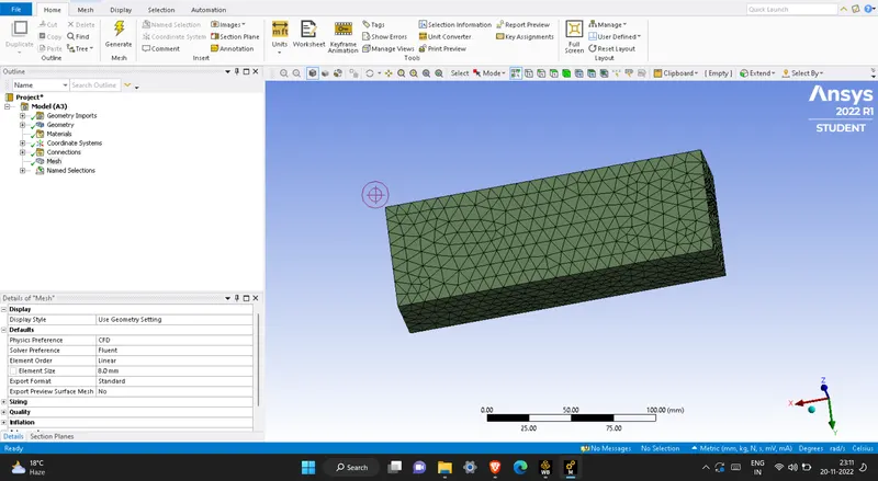
> Inner parts have body sizing having mesh element size of 1mm.
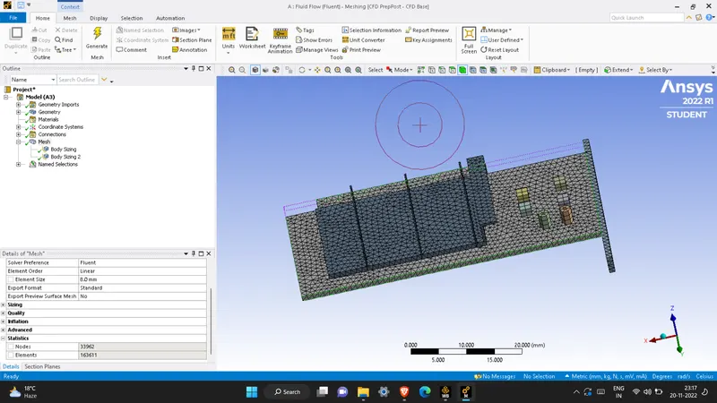
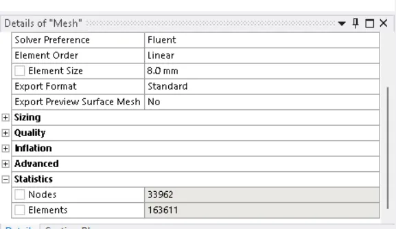
> Total number of mesh elements are 163611.
CASE 2.1: FINE MESH WITH INLET VELOCITY OF 5m/s.
SETUP:
| SOLVER TYPE | PRESSURE BASED |
| SOLVER TIME | STEADY STATE |
| ENERGY | ON |
| VISCOUS MODEL | K-EPSILON |
| MATERIALS |
PCB - POLYSTYRENE PROCESSOR - SILICON FINS - ALUMINIUM |
| CELL ZONES | Assiginig the diifrent material and type of material for diiffent zones of the geometry. |
| SOURCE TERM | ON (PROCESSOR USED AS SOURCE TERM WITH HEAT GENERATION OF 31250000 W/m^3 |
| BOUNDARY CONDITIONS |
INLET - VELOCITY INLET WITH VELOCITY OF 5M/S AND TEMPERATURE IS 300K. OUTLET - PRESSURE OUTLET WITH ATMOSPHERIC CNDITIONS |
| METHOD | COUPLED |
| NO. OF ELEMENTS | 163611 |
RESULTS:
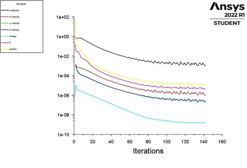
> SCALED RESIDUALS:
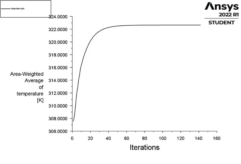
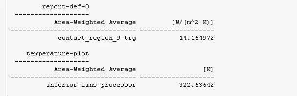
> TEMPERATURE PLOT AT INTERFACE OF PROCESSOR AND FINS:
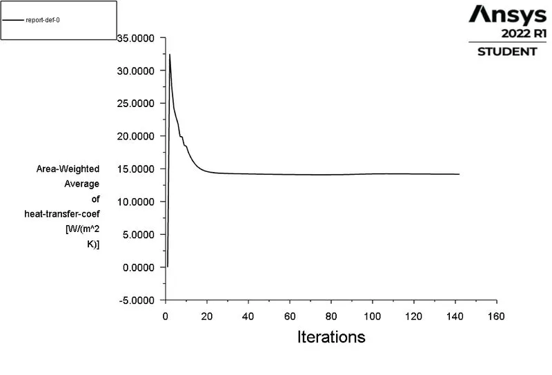
> HEAT TRANSFER COEFFICIENT PLOT FOR PROCESSOR WALL WHICH IS EXPOSED TO AIR:
POST PROCESSING:
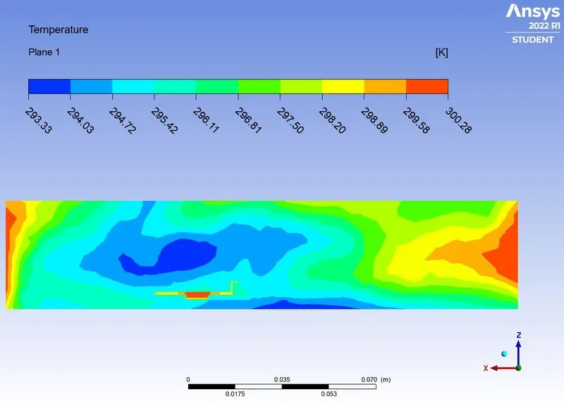
> TEMPERATURE CONTOUR:
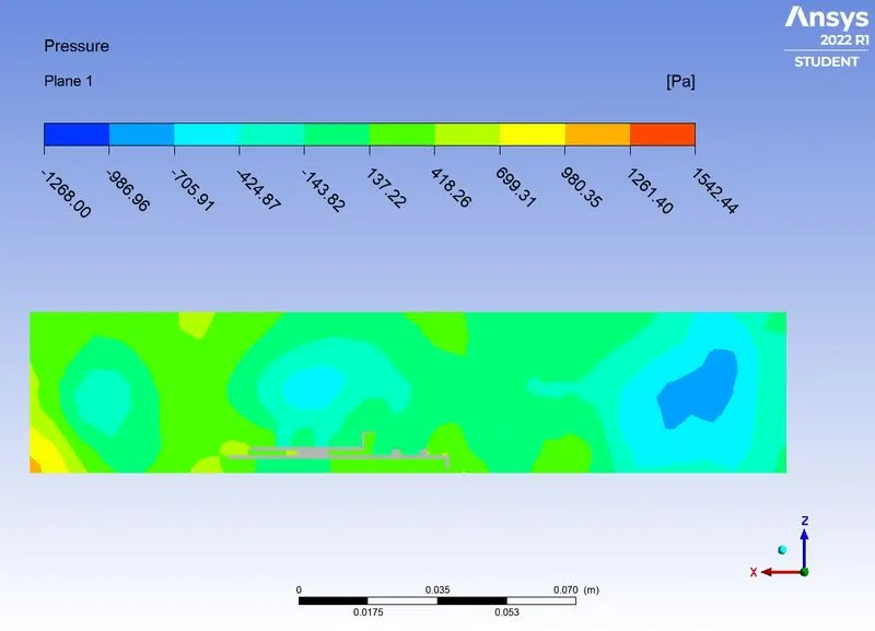
> PRESSURE CONTOUR:
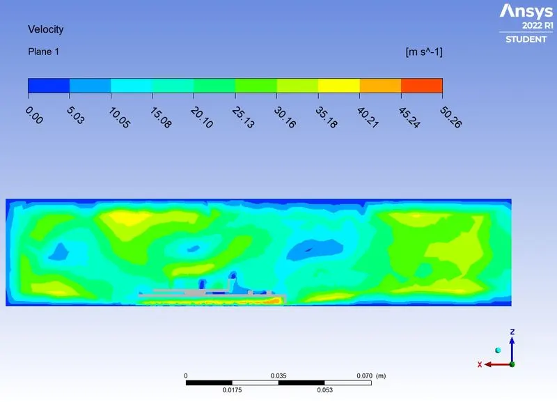
> VELOCITY CONTOUR:
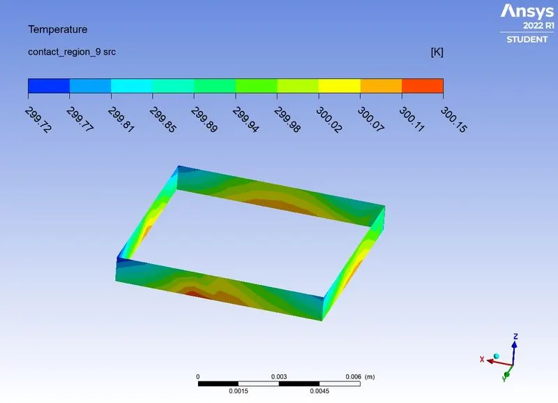
> TEMPERATURE AT PROCESSOR WALL:
> TEMPERATURE AT PCB:
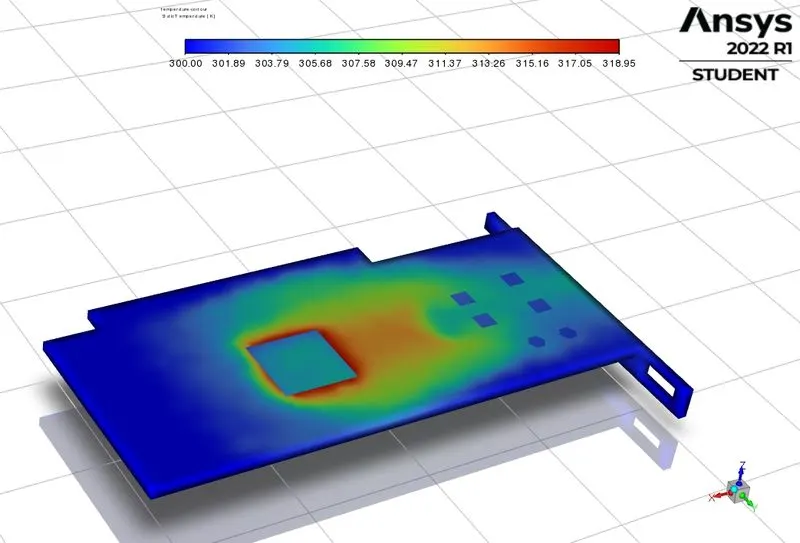
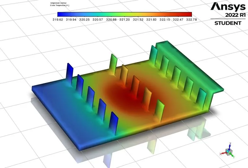
> TEMPERATURE AT FINS:
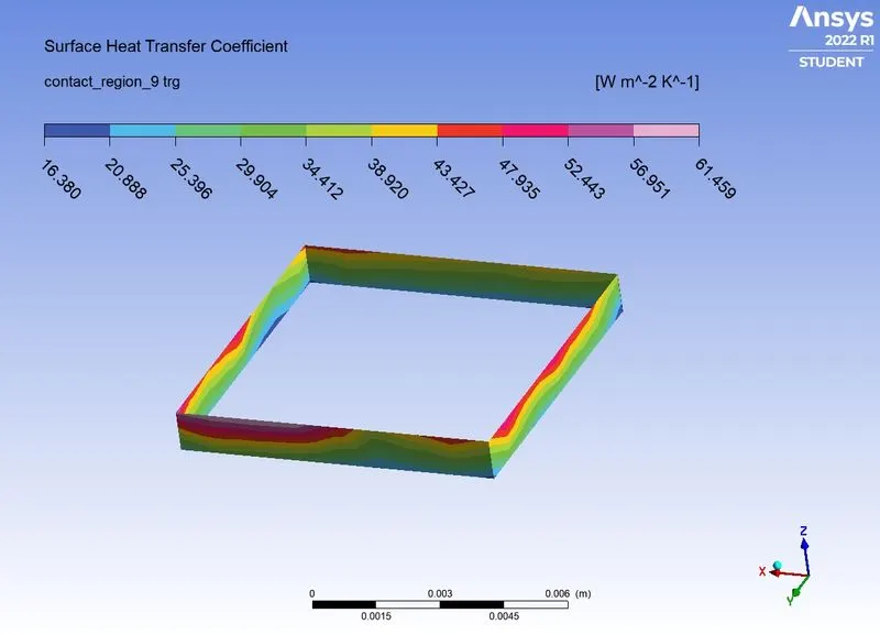
> HEAT TRANSFER COEFFICIENT AT PROCESSOR WALL:
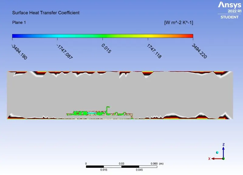
> HEAT TRANSFER COEFFICIENT CONTOUR:
CASE 2.2: FINE MESH WITH INLET VELOCITY OF 3m/s.
SET UP:
| SOLVER TYPE | PRESSURE BASED |
| SOLVER TIME | STEADY STATE |
| ENERGY | ON |
| VISCOUS MODEL | K-EPSILON |
| MATERIALS |
PCB - POLYSTYRENE PROCESSOR - SILICON FINS - ALUMINIUM |
| CELL ZONES | Assiginig the diifrent material and type of material for diiffent zones of the geometry. |
| SOURCE TERM | ON (PROCESSOR USED AS SOURCE TERM WITH HEAT GENERATION OF 31250000 W/m^3 |
| BOUNDARY CONDITIONS |
INLET - VELOCITY INLET WITH VELOCITY OF 3M/S AND TEMPERATURE IS 300K. OUTLET - PRESSURE OUTLET WITH ATMOSPHERIC CNDITIONS |
| METHOD | COUPLED |
| NO. OF ELEMENTS | 163611 |
RESULTS:
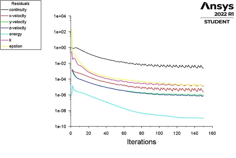
> SCALED RESIDUALS:
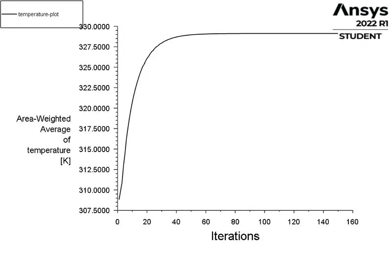
> TEMPERATURE PLOT AT INTERFACE OF PROCESSOR AND FINS:
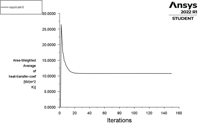
> HEAT TRANSFER COEFFICIENT PLOT FOR PROCESSOR WALL WHICH IS EXPOSED TO AIR:
 '
'
POST PROCESSING:
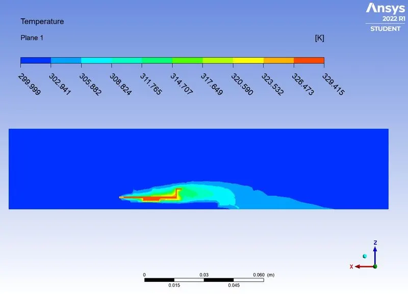
> TEMPERATURE CONTOUR:
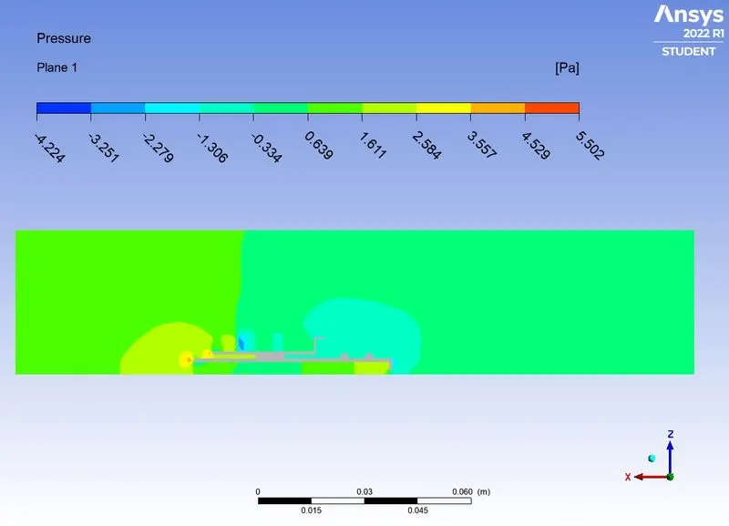
> PRESSURE CONTOUR:
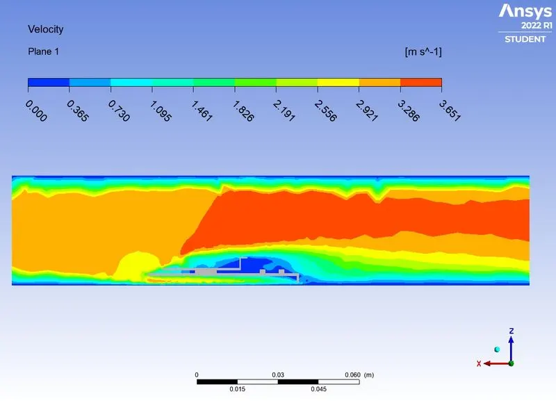
> VELOCITY CONTOUR:
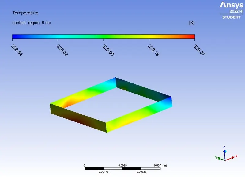
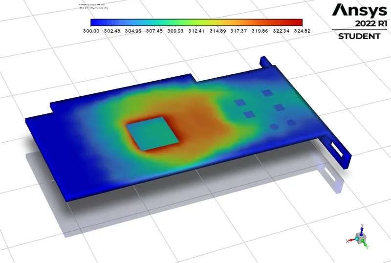
> TEMPERATURE AT PROCESSOR WALL:
> TEMPERATURE AT PCB:
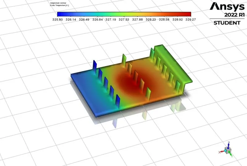
> TEMPERATURE AT FINS:
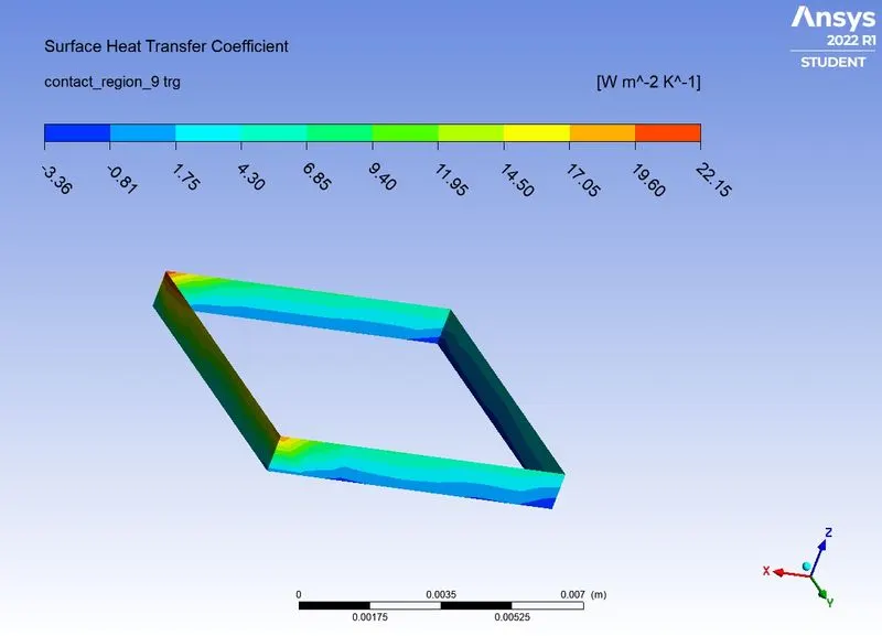
> HEAT TRANSFER COEFFICIENT AT PROCESSOR WALL:
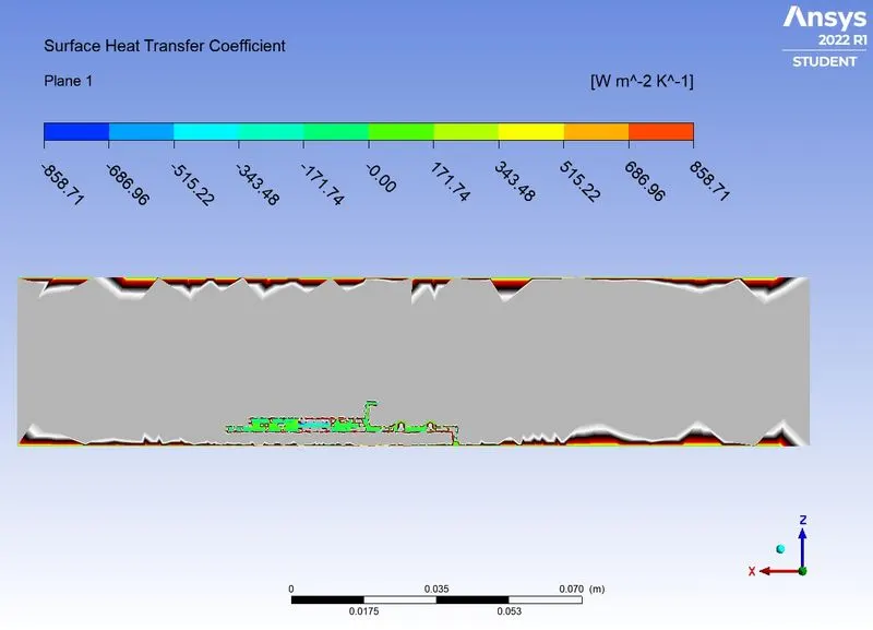
> HEAT TRANSFER COEFFICIENT CONTOUR:
`
CASE 2.3: FINE MESH WITH INLET VELOCITY OF 1m/s.
| SOLVER TYPE | PRESSURE BASED |
| SOLVER TIME | STEADY STATE |
| ENERGY | ON |
| VISCOUS MODEL | K-EPSILON |
| MATERIALS |
PCB - POLYSTYRENE PROCESSOR - SILICON FINS - ALUMINIUM |
| CELL ZONES | Assiginig the diifrent material and type of material for diiffent zones of the geometry. |
| SOURCE TERM | ON (PROCESSOR USED AS SOURCE TERM WITH HEAT GENERATION OF 31250000 W/m^3 |
| BOUNDARY CONDITIONS |
INLET - VELOCITY INLET WITH VELOCITY OF 1M/S AND TEMPERATURE IS 300K. OUTLET - PRESSURE OUTLET WITH ATMOSPHERIC CNDITIONS |
| METHOD | COUPLED |
| NO. OF ELEMENTS | 163611 |
RESULTS:
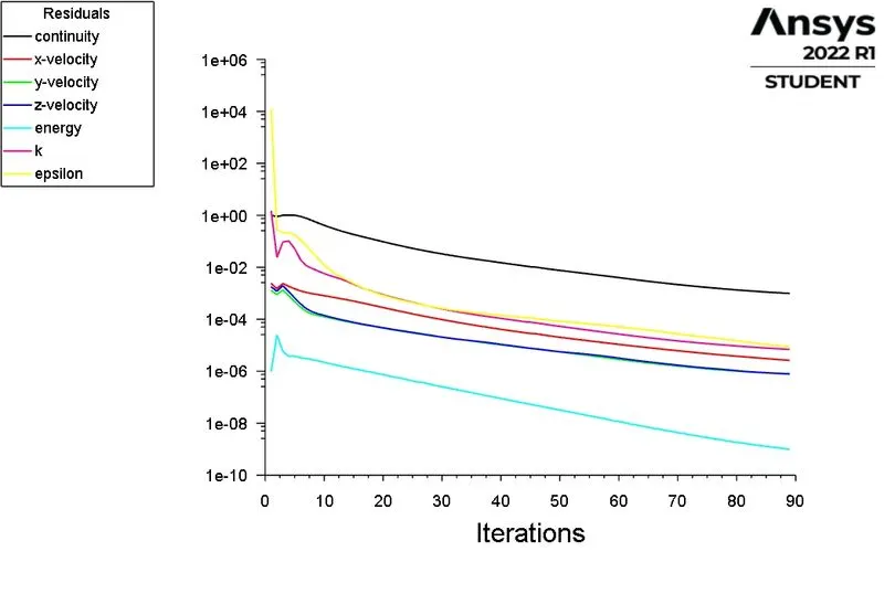
> SCALED RESIDUALS:
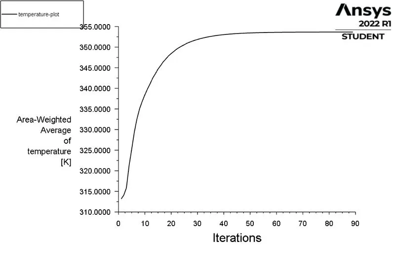
> TEMPERATURE PLOT AT INTERFACE OF PROCESSOR AND FINS:
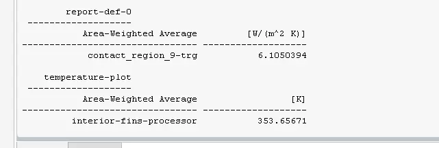
> HEAT TRANSFER COEFFICIENT PLOT FOR PROCESSOR WALL WHICH IS EXPOSED TO AIR:
POST PROCESSING:
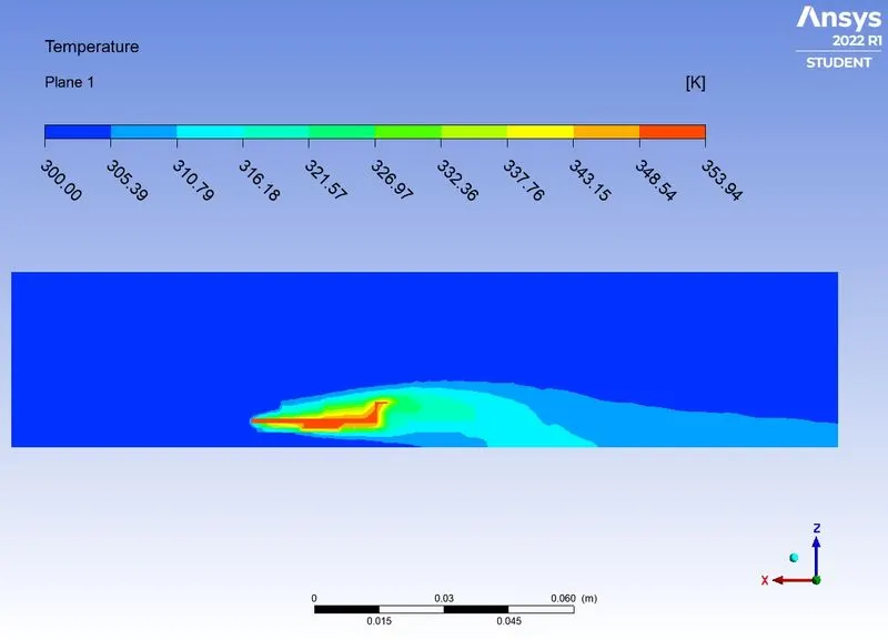
> TEMPERATURE CONTOUR:
> PRESSURE CONTOUR:
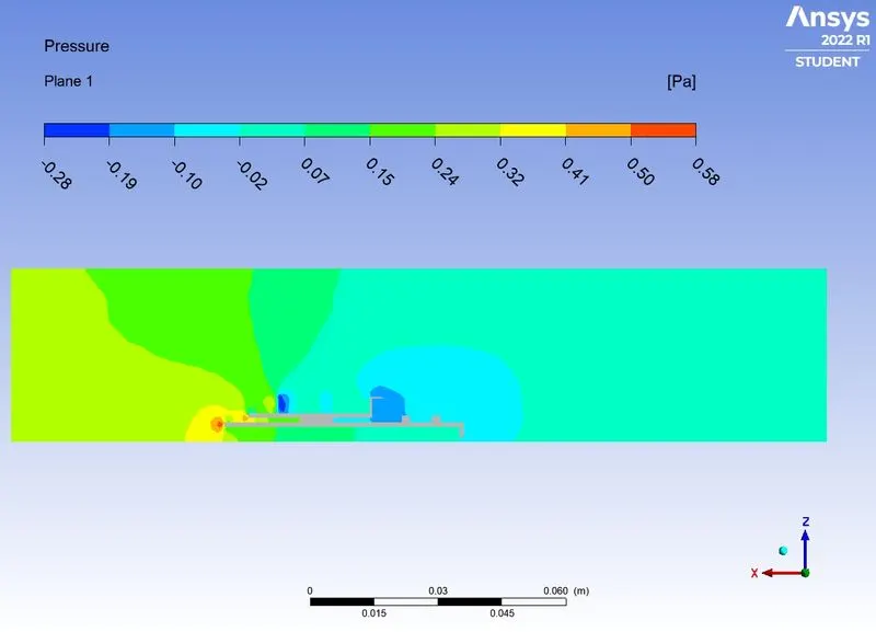
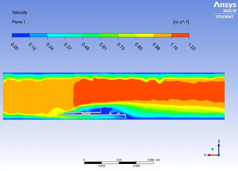
> VELOCITY CONTOUR:
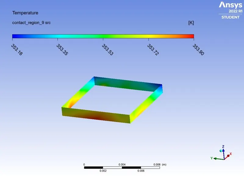
> TEMPERATURE AT PROCESSOR WALL:
> TEMPERATURE AT PCB:
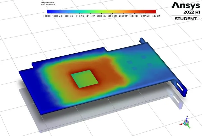
> TEMPERATURE AT FINS:
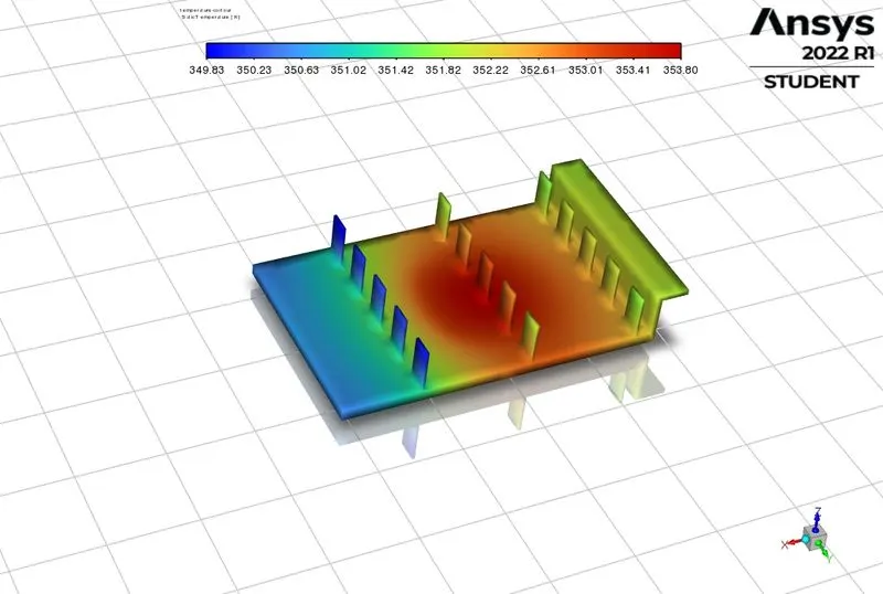
> The max temperature attained by the processor will always vary, like it increased when the air flow was less and decreased when it was more. hence proper cooling of such electronic devices is necessary for efficient functioning.
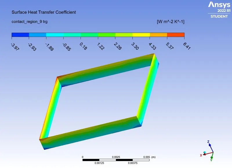
> HEAT TRANSFER COEFFICIENT AT PROCESSOR WALL:
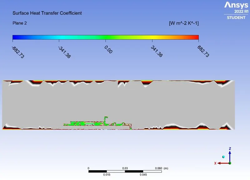
> HEAT TRANSFER COEFFICIENT CONTOUR:
> CONCLUSIONS:
| CASES | AVERAGE TEMPERATURE AT PROCESSOR AND FINS INTERFACE | HEAT TRANSFER COEFFICIENT AT PROCESSOR WALL EXPOSED TO AIR |
| COASRE MESH WITH VELOCITY OF 5m/s | 328.654 k | 15.287 W/m^2k |
| COARSE MESH WITH VELOCITY OF 3m/s | 336.296 | 8.006 |
| COARSE MESH WITH VELOCITY OF 1m/s | 359.43 | 3.398 |
| FINE MESH WITH VELOCITY OF 5 m/s | 322.745 | 14.657 |
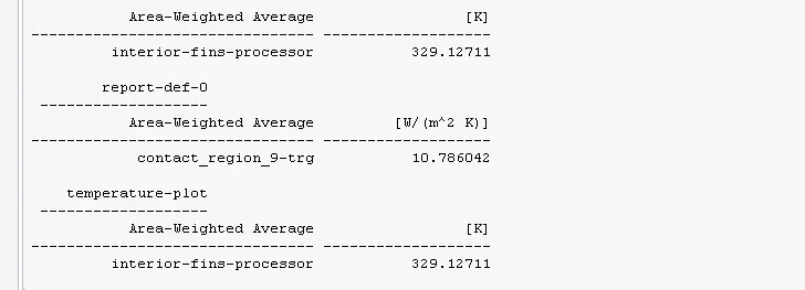
| FINE MESH WITH VELOCITY OF 3m/s | 329.12 | 10.786 |
| FINE MESH WITH VELOCITY OF 1m/s | 353.65 | 6.105 |
> Heat transfer coefficient is never a property of the material unlike thermal conductivity is the proprty of the material.
> Heat transfer coefficient is depends upon some of the thermophysical property of the fluid like density, viscosity,specific heat and thermal conductivity. in the above problem as the velocity of the air increases the heat transfer coefiicient at processor wall increase.
> As the velocity of the air increases then the value of the temperature at the processor wall decreases.
> We conclude the solution convergence by first observing the residuals where all the equations converged . Secondly the desired results where achieved as we expected it. i.e the idea in mind of what the cht simulation results would prove was infact observed in every iteration of the solution which leads us to conclude a fully converged solution.
> Proper meshing has extremely important advantages as we observed from case 2a and B having significant differences in terms of maximum temperature.