Week 10 - Simulating Combustion of Natural Gas.
AIM: SIMULATING COMBUSTION OF NATURAL GAS.
PROBLEM STATEMENT:
Part I
Perform a combustion simulation on the combustor model and plot the variation of the mass fraction of the different species’ in the simulation using line probes at different locations of the combustor as shown in Fig. You need to plot for CO2, H2O, CH4, N2, O2, NOx emissions & Soot formation.
Part II
As you must have observed from the above simulation, the Nox and soot is getting formed at the outlet of the combustor. Such formation has harmful effects on the environment and humans. The stringent government norms also demand the least formation of Nox and soot and to satisfy those requirements, you need to check the effect of adding the water in the fuel.
In this part, you need to add the water content in the fuel from 5% to 30% by mole and observe the effect of it on the results. It is necessary to provide line plots and contours to prove your claim.
You can use the parametric study approach if required.
Note:-
1. Use methane-air-2step as a mixture material than methane-air. [It allows to add water in the fuel or air]
2. Use a one-step soot model to calculate the soot formation.
INTRODUCTION THEORY:
1. Combustion:
Combustion, or burning, is a high-temperature exothermic redox chemical reaction between a fuel (the reductant) and an oxidant, usually, atmospheric oxygen, that produces oxidized, often gaseous products, in a mixture termed as smoke. Combustion does not always result in fire, because a flame is only visible when substances undergoing combustion vapourise, but when it does, a flame is a characteristic indicator of the reaction. While the activation energy must be overcome to initiate combustion (e.g., using a lit match to light a fire), the heat from a flame may provide enough energy to make the reaction self-sustaining. Combustion is often a complicated sequence of elementary radical reactions. Solid fuels, such as wood and coal, first undergo endothermic pyrolysis to produce gaseous fuels whose combustion then supplies the heat required to produce more of them. Combustion is often hot enough that incandescent light in the form of either glowing or a flame is produced. A simple example can be seen in the combustion of hydrogen and oxygen into water vapour, a reaction commonly used to fuel rocket engines. This reaction releases 242 kJ/mol of heat and reduces the enthalpy accordingly (at constant temperature and pressure):
- 2H2(g) + O2(g) → 2H2O(g)
Combustion of an organic fuel in air is always exothermic because the double bond in O2 is much weaker than other double bonds or pairs of single bonds, and therefore the formation of the stronger bonds in the combustion products CO
2 and H2O results in the release of energy.
Stoichiometric combustion of a hydrocarbon in oxygen:
Generally, the chemical equation for stoichiometric combustion of a hydrocarbon in oxygen is:

Where, 
For example, the stoichiometric burning of propane in oxygen is

2. Chemical kinetics:
Chemical kinetics, also known as reaction kinetics, is the branch of physical chemistry that is concerned with understanding the rates of chemical reactions. It is to be contrasted with thermodynamics, which deals with the direction in which a process occurs but in itself tells nothing about its rate. Chemical kinetics includes investigations of how experimental conditions influence the speed of a chemical reaction and yield information about the reaction's mechanism and transition states, as well as the construction of mathematical models that also can describe the characteristics of a chemical reaction.
3. Chemical reaction model:
Chemical reaction models transform physical knowledge into a mathematical formulation that can be utilized in computational simulation of practical problems in chemical engineering. Computer simulation provides the flexibility to study chemical processes under a wide range of conditions. Modelling a chemical reaction involves solving conservation equations describing convection, diffusion, and reaction source for each component species.
Series transport equation-

Ri is the net rate of production of species i by chemical reaction and Si is the rate of creation by addition from the dispersed phase and the user-defined source. Ji is the diffusion flux of species i, which arises due to concentration gradients and differs in both laminar and turbulent flows. In turbulent flows, computational fluid dynamics also considers the effects of turbulent diffusivity. The net source of chemical species i due to reaction, Ri which appeared as the source term in the species transport equation is computed as the sum of the reaction sources over the NR reactions among the species.
Reaction rate models:
a. Laminar finite rate model:
The laminar finite rate model computes the chemical source terms using the Arrhenius expressions and ignores turbulence fluctuations. This model provides the exact solution for laminar flames but gives inaccurate solution for turbulent flames, in which turbulence highly affects the chemistry reaction rates, due to highly non-linear Arrhenius chemical kinetics. However, this model may be accurate for combustion with small turbulence fluctuations, for example, supersonic flames.
b. Eddy dissipation model:
The eddy dissipation model, based on the work of Magnussen and Hjertager, is a turbulent-chemistry reaction model. Most fuels are fast burning and the overall rate of reaction is controlled by turbulence mixing. In the non-premixed flames, turbulence slowly mixes the fuel and oxidizer into the reaction zones where they burn quickly. In premixed flames, the turbulence slowly mixes cold reactants and hot products into the reaction zones where the reaction occurs rapidly. In such cases, the combustion is said to be mixing-limited, and the complex and often unknown chemical kinetics can be safely neglected. In this model, the chemical reaction is governed by large-eddy mixing time scale. Combustion initiates whenever there is turbulence present in the flow. It does not need an ignition source to initiate the combustion. This type of model is valid for the non-premixed combustion, but for the premixed flames the reactant is assumed to burn at the moment it enters the computation model, which is a shortcoming of this model as in practice the reactant needs some time to get to the ignition temperature to initiate the combustion.
Factors affecting reaction rate:
1. Nature of reactants
2. Physical state
3. Surface area of solid-state
4. Concentration
5. Temperature
6. Catalysts
7. Pressure
8. Absorption of light
Applications:
The mathematical models that describe chemical reaction kinetics provide chemists and chemical engineers with tools to better understand and describe chemical processes such as food decomposition, microorganism growth, stratospheric ozone decomposition, and the chemistry of biological systems. These models can also be used in the design or modification of chemical reactors to optimize product yield, more efficiently separate products, and eliminate environmentally harmful by-products. When performing catalytic cracking of heavy hydrocarbons into gasoline and light gas, for example, kinetic models can be used to find the temperature and pressure at which the highest yield of heavy hydrocarbons into gasoline will occur.
Chemical Kinetics is frequently validated and explored through modelling in specialized packages as a function of ordinary differential equation-solving (ODE-solving) and curve-fitting.
4. Mass fraction:
A mass fraction can also be expressed, with a denominator of 100, as a percentage by mass. It is one way of expressing the composition of a mixture in a dimensionless size; mole fraction (percentage by moles, mol%) and volume fraction (percentage by volume, vol%) are others.
When the prevalences of interest are those of individual chemical elements, rather than of compounds or other substances, the term mass fraction can also refer to the ratio of the mass of an element to the total mass of a sample. In these contexts, an alternative term is a mass per cent composition. The mass fraction of an element in a compound can be calculated from the compound's empirical formula or its chemical formula.
5. Nitrogen Oxide (NOx) emissions:
Nitrogen dioxide is an irritant gas, which at high concentrations causes inflammation of the airways. When nitrogen is released during fuel combustion it combines with oxygen atoms to create nitric oxide (NO). This further combines with oxygen to create nitrogen dioxide (NO2). Nitric oxide is not considered to be hazardous to health at typical ambient concentrations, but nitrogen dioxide can be. Nitrogen dioxide and nitric oxide are referred to together as oxides of nitrogen (NOx).
NOx gases react to form smog and acid rain as well as being central to the formation of fine particles (PM) and ground-level ozone, both of which are associated with adverse health effects.
6. Soot formations:
Soot forms when hydrocarbon fuels such as oil, natural gas, and wood are burned. Soot particles form when gaseous molecules are heated to high temperatures, and they don't easily turn back into gaseous molecules the way water droplets do when they are heated. Soot as an airborne contaminant in the environment has many different sources, all of which are results of some form of pyrolysis. They include soot from coal-burning, internal-combustion engines, power-plant boilers, hog-fuel boilers, ship boilers, central steam-heat boilers, waste incineration, local field burning, house fires, forest fires, fireplaces, and furnaces. These exterior sources also contribute to the indoor environment sources such as smoking of plant matter, cooking, oil lamps, candles, quartz/halogen bulbs with settled dust, fireplaces, exhaust emissions from vehicles, and defective furnaces.
PROCEDRE:
1. Geometry:
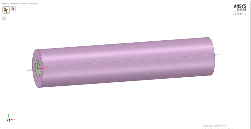
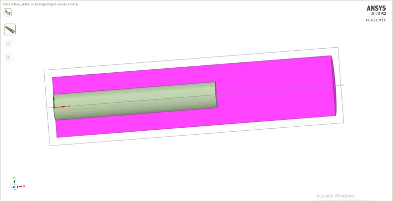
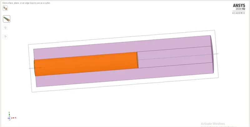
a. Upload the combustor model onto SpaceClaim, since it is a 3D model and we are only interested in the 2D geometry of the combustor. Therefore, we need to split the body by 3/4th and select the plane XY plane region of geometry since we are using the axisymmetric condition.
3D model of the combustor:
Splitting the body:
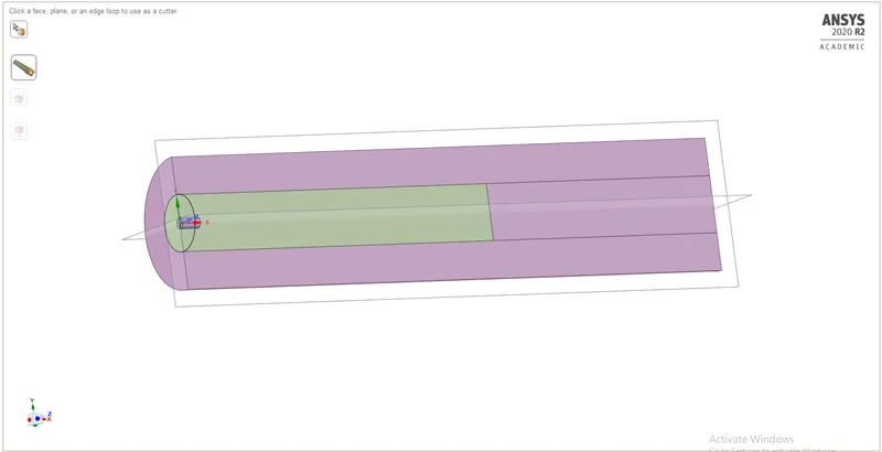
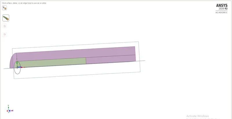
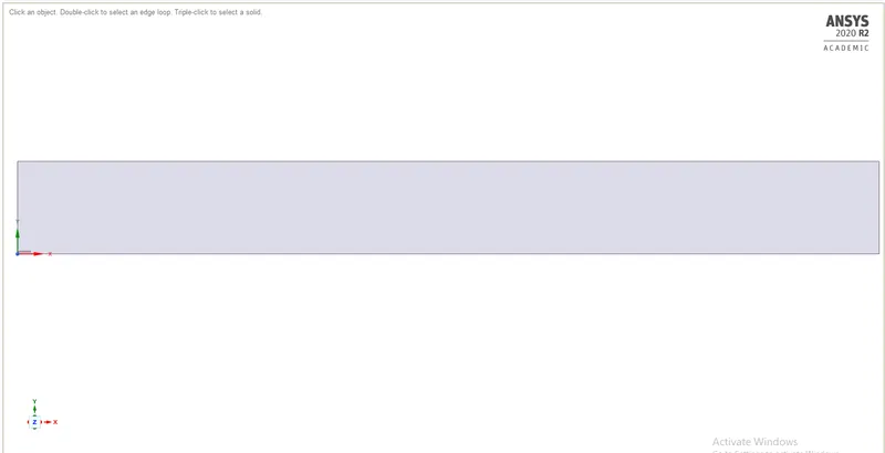
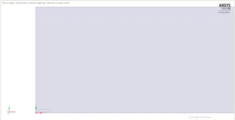
b. After splitting the body, select the 2D Plane normal to the Z-axis and copy that geometry to a new design sheet and delete the old one since we do not need it.
2D geometry:
MESHING:
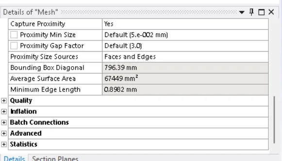
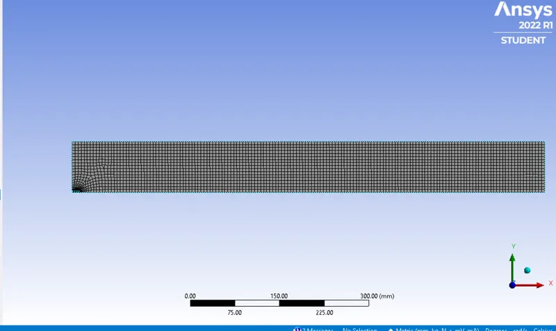
> Perform the mesh with element size of 5mm.
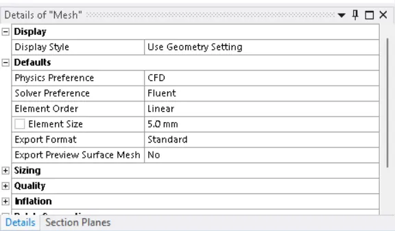
> Enable capture proximity. and set number of cell across the gap as 3.
> Perform name selection.
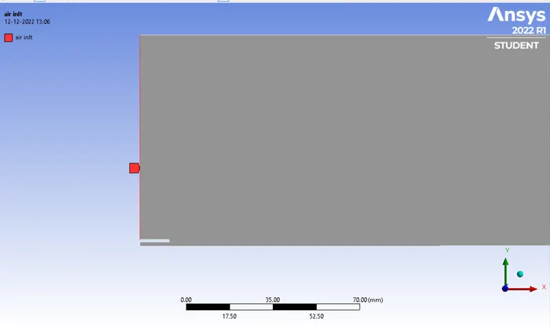
>Air Inlet
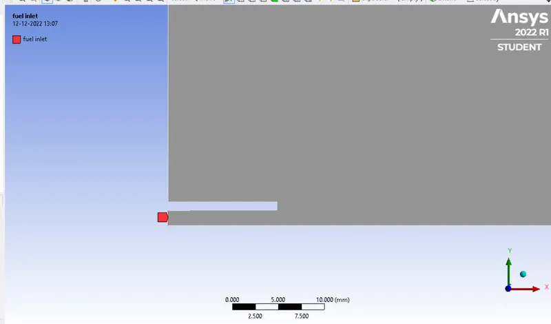
> Fuel inlet:
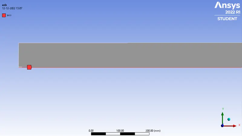
> Axis:
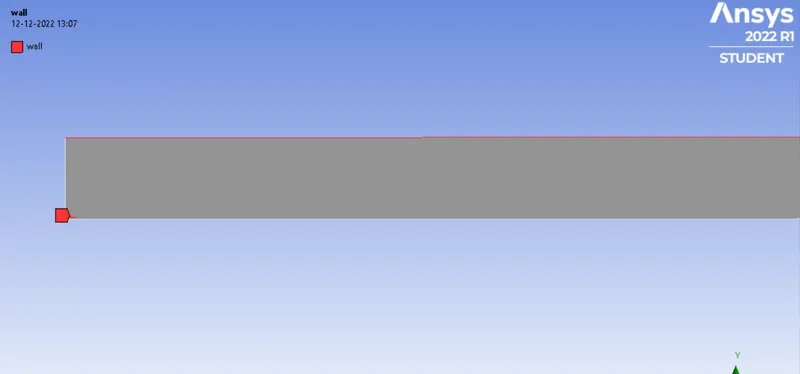
wall:
Setup:
case 1: fuel as 1 and water as 0.
| solver time | steady |
| solver type | pressure based |
| velocity formation | Absolute |
| 2D space | axi symmetric |
| energy | enable |
| viscous model | k-epsilon+standard+ standard wall functions |
| species model | species transport |
| NOx model | on |
| soot model | one step |
| material |
water fuel(CH4) |
| solution method | coupled |
| Number of iterations | 1000 |
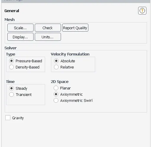
> perform the general settings for setup.
solver time as steady state, solver type as pressure based and 2d space as axisymmetric.
> Enable energy and choose viscous model as k-epsilon standard+standard wall functions.
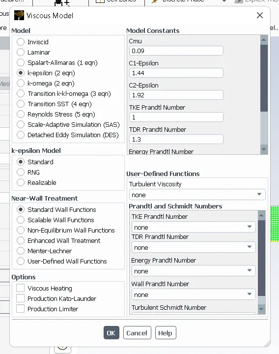
> if we donot turn on the turbulence model so we will not get eddy dissipiation model because eddy dissipiation model is a turbulence chemistry interaction model.
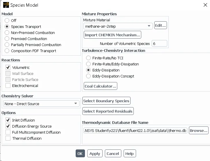
> select species and set species model.
Species > species tranport > volumetric( because it is going to take space in the gas phase) > inlet diffusion is turned on.
> Inlet diffusion is turned on because when we are using pressure based solver your diffusion term are not included or not solved at inlet because we donot know what are diffusion coefficient are going to be or how diffusion are going to be take place.
> Also enable diffusion energy sources.
> Mixture properties > mixture material > methane air > turbulence chemistry interaction > eddy dissipiation > ok.
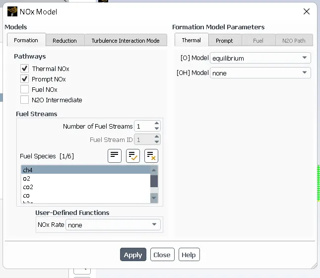
> Enable NOx model.
Physics > more > NOx model > formation pathways > enable thermal NOX and Prompt NOx > select fuel species as CH4 > select number of fuel streams as 1.
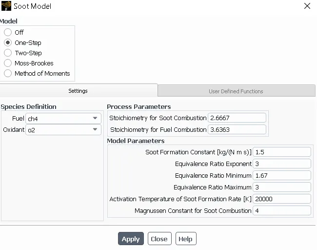
> Enable soot model.
Select model as one step > fuel as CH4 and oxidant as O2.
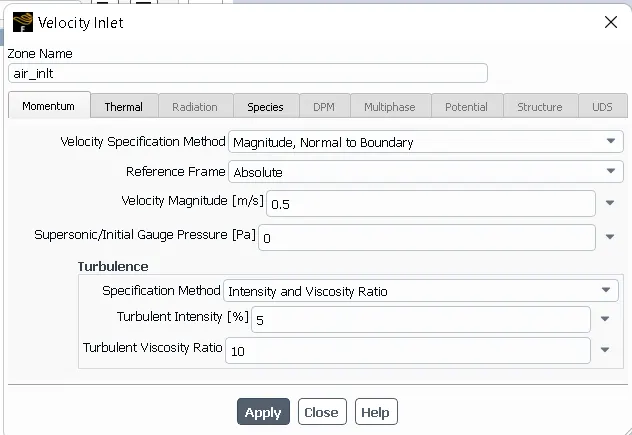
> select boundaries.
select air inlet > velocity as 0.5m/s > temperature as 300k > species > select mass fraction of O2 as 0.23.
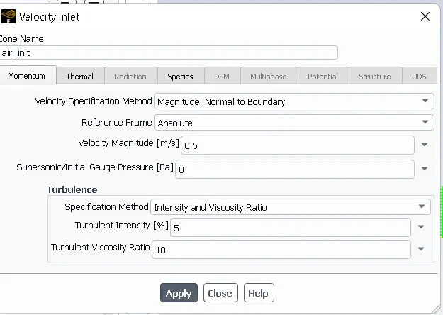
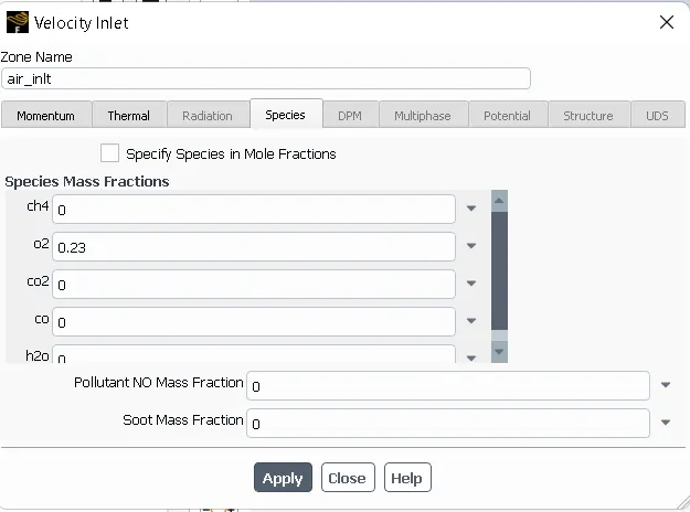
> Select fuel inlet > select velocity magnitude as 80 > temperature as 300k > and species mass fraction of Ch4 as 1.
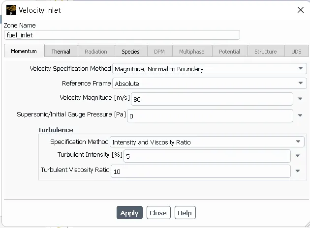
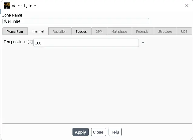
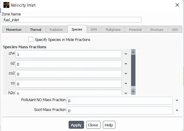
> In real life we have burner where fuel and air are burn with the help of ignition source but in this case we are using the eddy dissipiation model the fuel burning rate is not govern by the presence of energy source it is govern by presence of turbulence so if the value of k and epsilon are high enogh so it will give the resonable value of time scale like charcteristic turbulence mixing time scale based on which the ansys fluent will automatically calculate the time for combustion.
> Stedy state temperature distribution enable to make sure that there is uniform temperature distribution at outlet. We really donot care about how the combustion started we care about how the combustion lokks like at the end.For these types of simulation we are using eddy dissipiation model beause it is very fast and in these type of scenerios basically it is steady flow device meaning there is inlet and outlet and afer some time the flow is going to reach steady state or pseudo steady state. it is not like an IC engine where we have events like intake valve open and intake valve close in thatbtype of scenerios this will not work well.So in that type of scenerios we are using the Finite trade chemistry model but that will be costly because we are solving several ordinary differential equations at every time step in every computational shell.
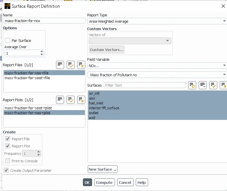
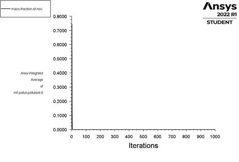
> Create the mass fraction of NOX report.
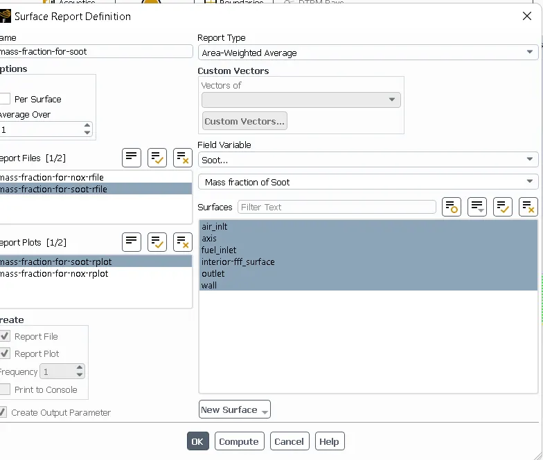
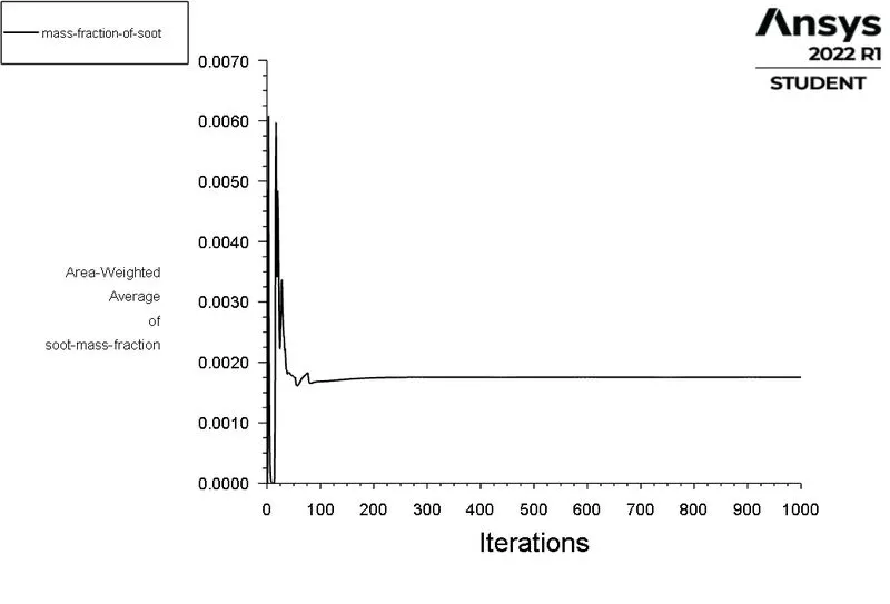
> craete the mass fraction of soot report.
> Initialize the problem using HYbrid initialization.
> Run the calculation for the 1000 iterations.
RESULTS:
CASE 1: MASS FRACTION OF CH4 AS 1 AND H2O AS 0.
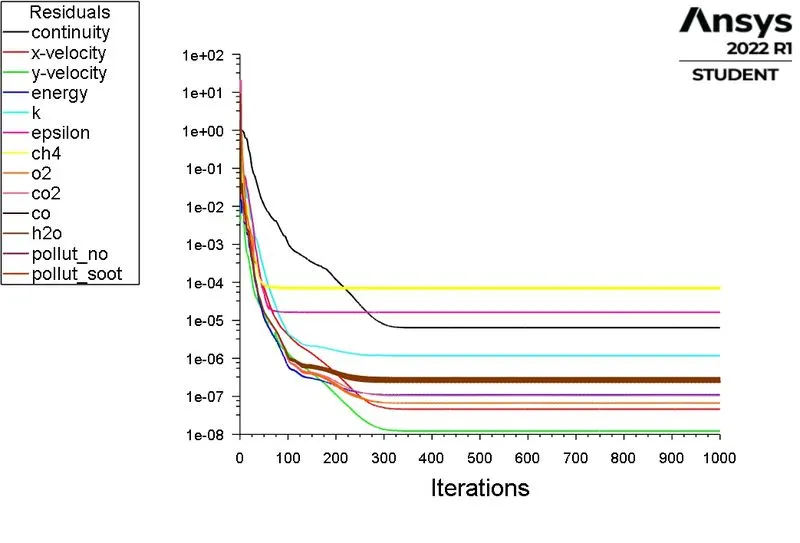
> Scaled residuals:
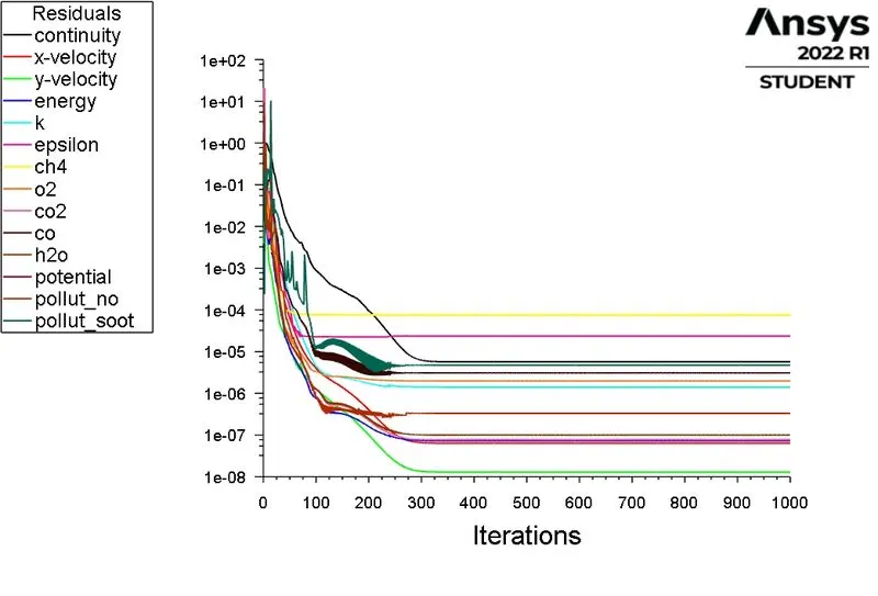
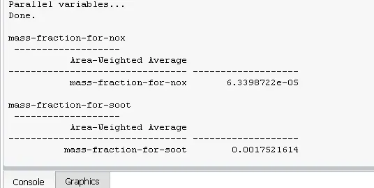
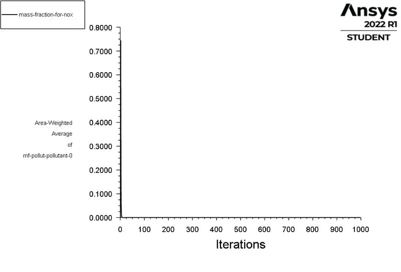
> Mass fraction of NOx report.
> Mass Fraction Of soot report:
POST PROCESSING:
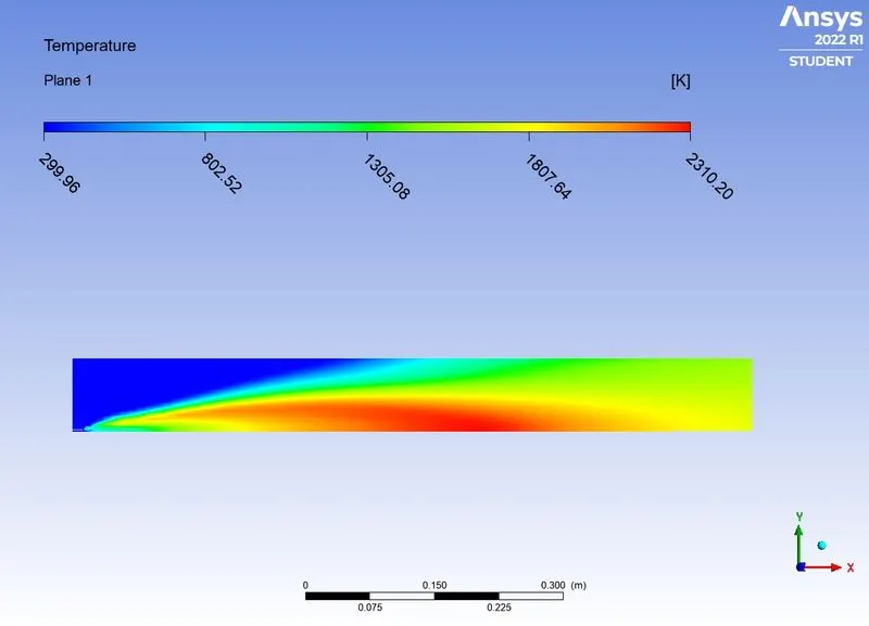
> TEmperature contour.
> contour for Mass fraction of NOx.
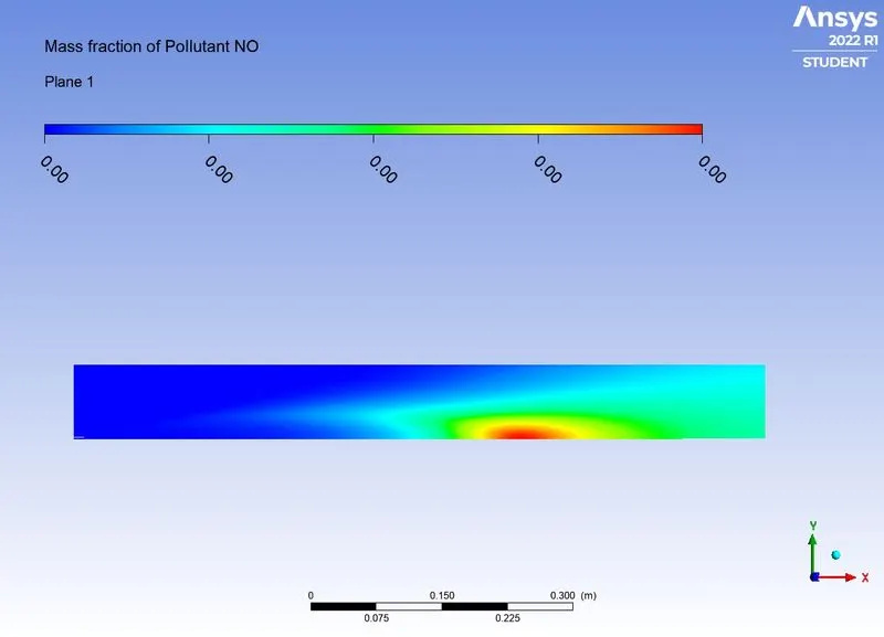
> Chart for mass fraction of NOx.
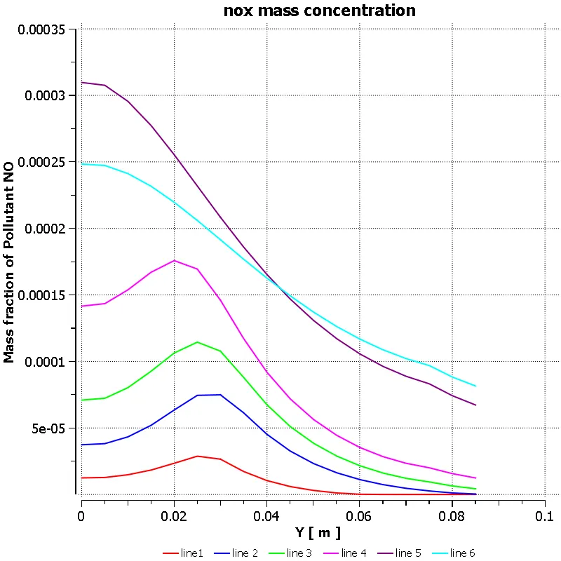
> Contour for mass fraction of soot.
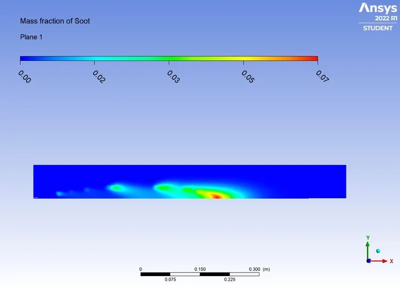
> chart for mass fraction of soot.
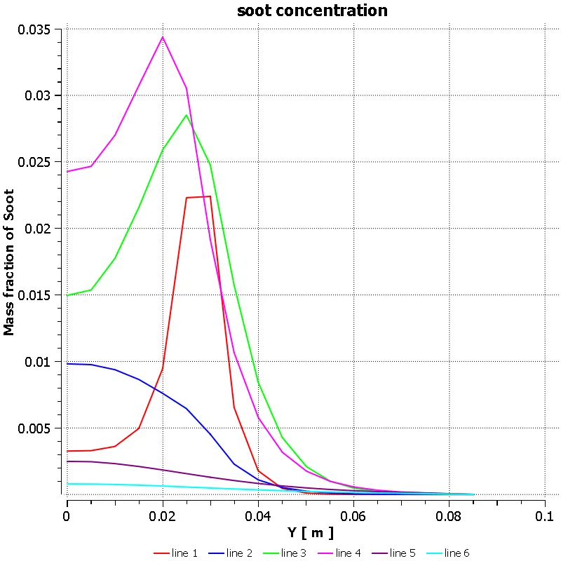
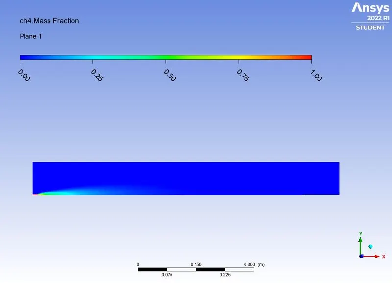
> contour for mass fraction of ch4.
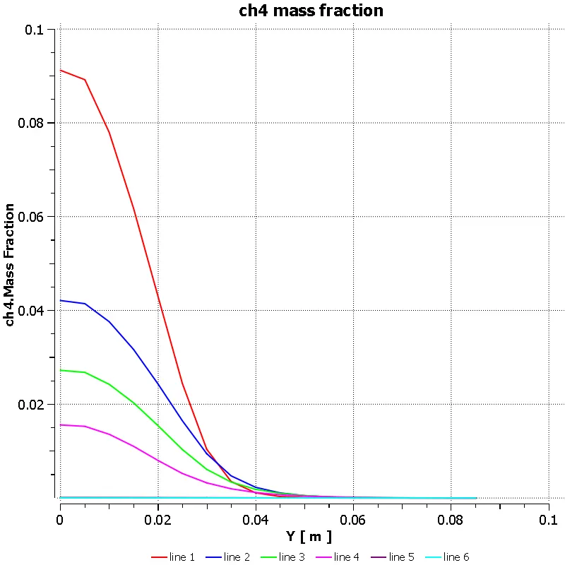
> chart for mass fraction of Ch4.
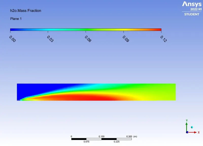
> contour for mass fraction of H2O.
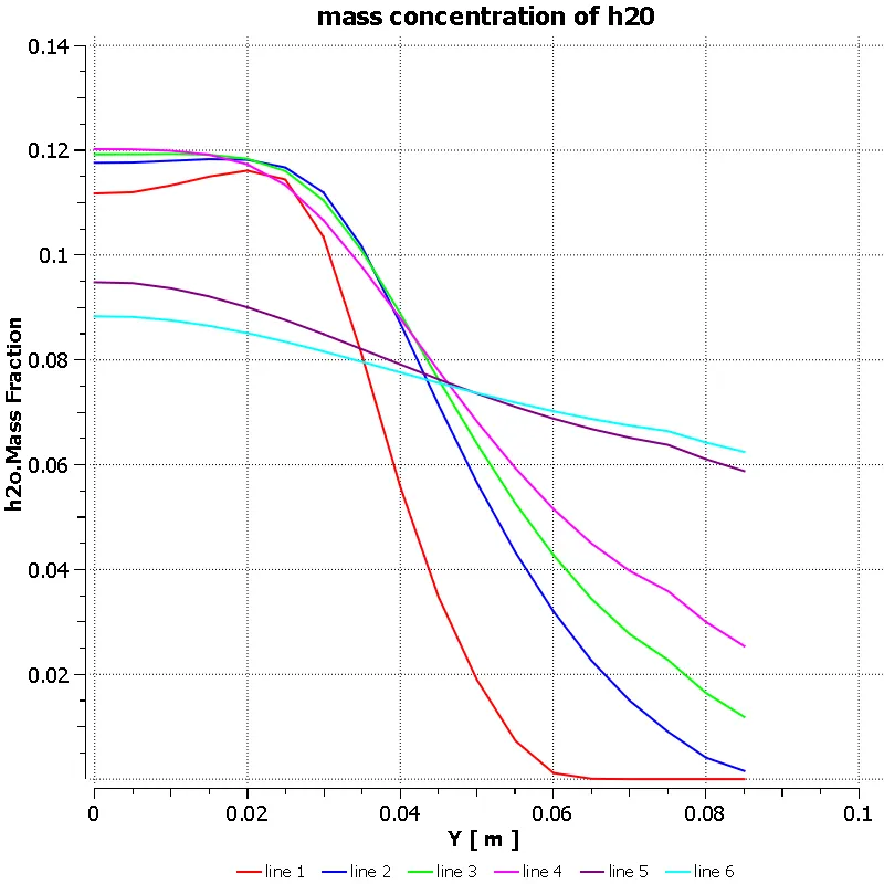
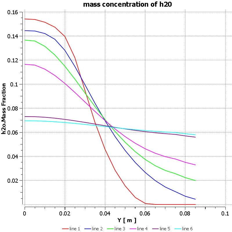
> Chart for mass fraction of H2O.
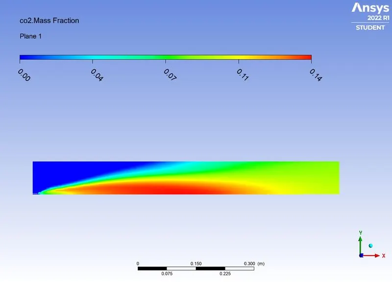
> Contour for mass fraction of CO2.
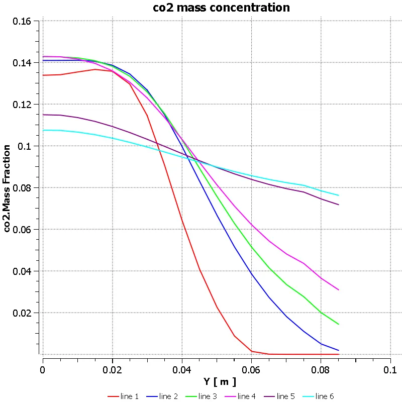
> Chart for mass fraction of CO2.
CASE 2: MASS FRACTION OF CH4 AS 0.9 AND WATER AS 0.1.
RESULTS:
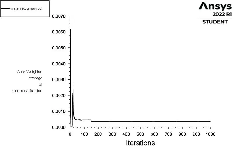
> Scaled residuals:
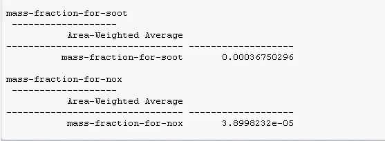
> Mass fraction of NOx report.
> Mass Fraction Of soot report:
POST PROCESSING:
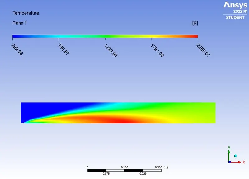
> TEmperature contour.
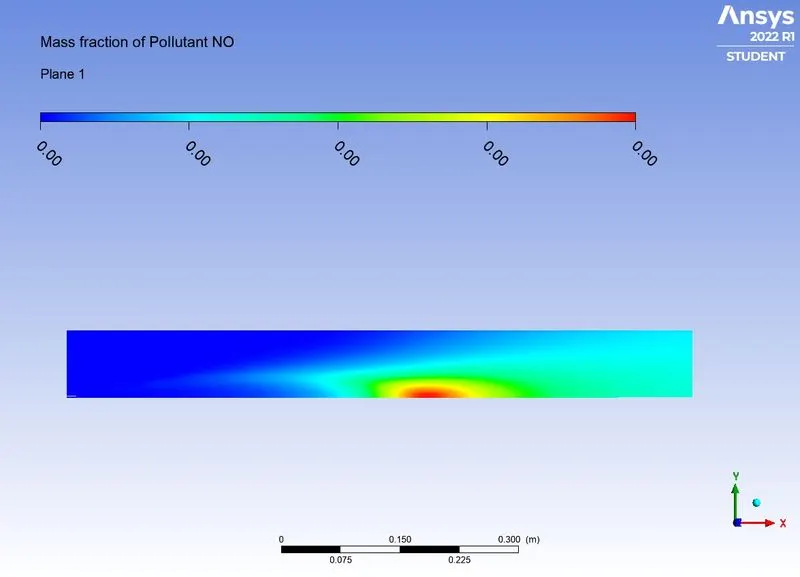
> contour for Mass fraction of NOx.
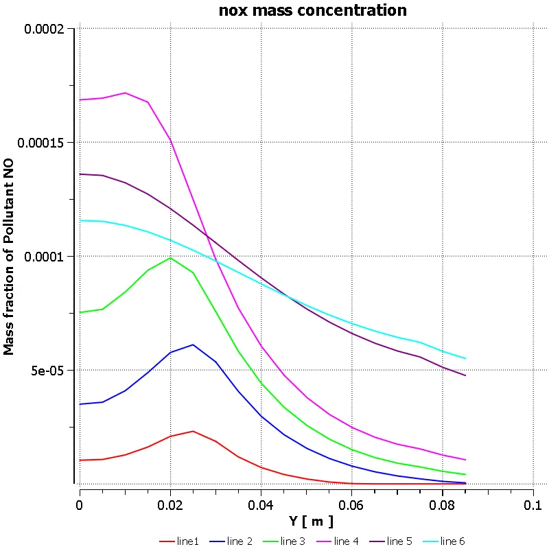
> Chart for mass fraction of NOx.
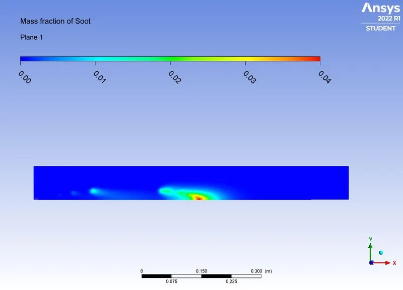
> Contour for mass fraction of soot.
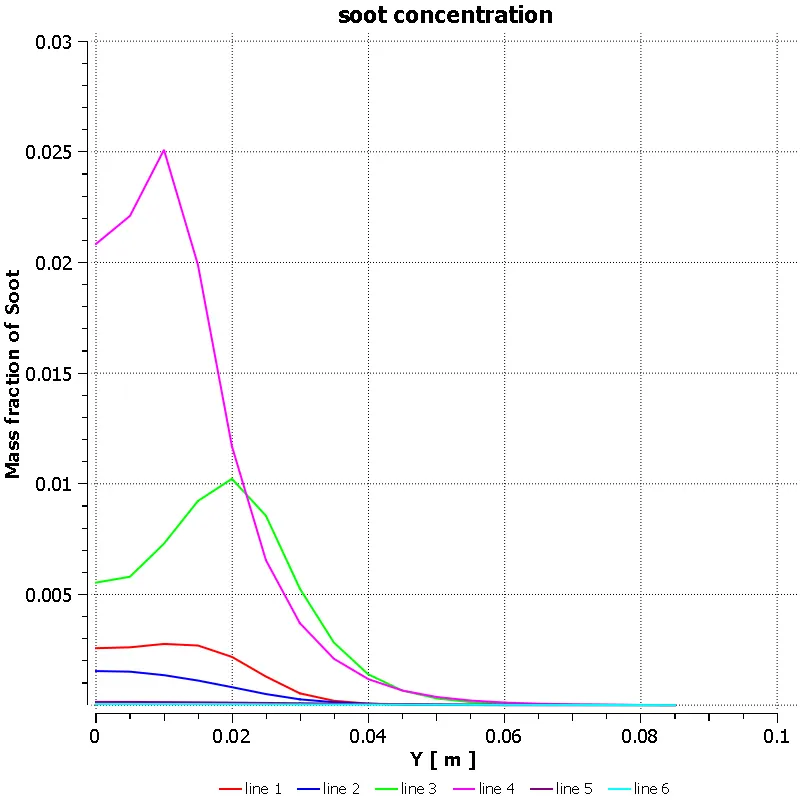
> chart for mass fraction of soot.
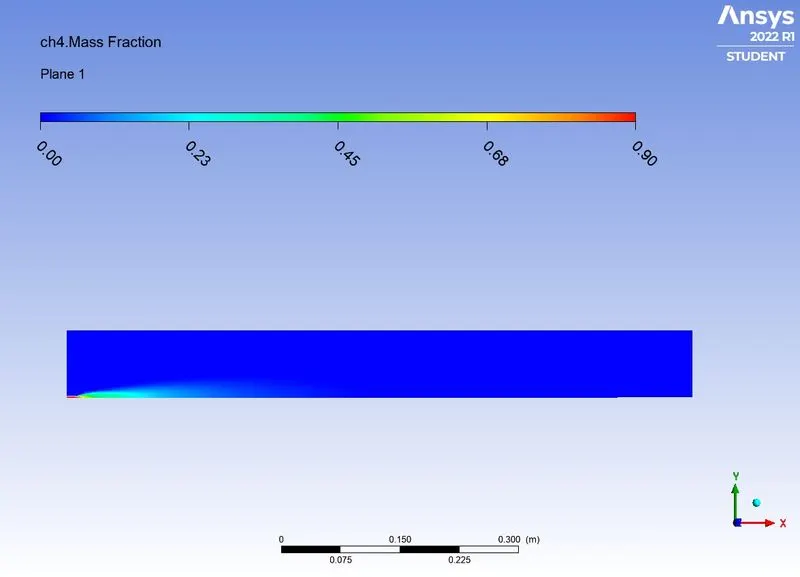
> contour for mass fraction of ch4.
> chart for mass fraction of Ch4
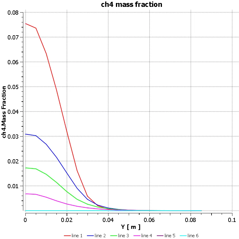
> contour for mass fraction of H2O.
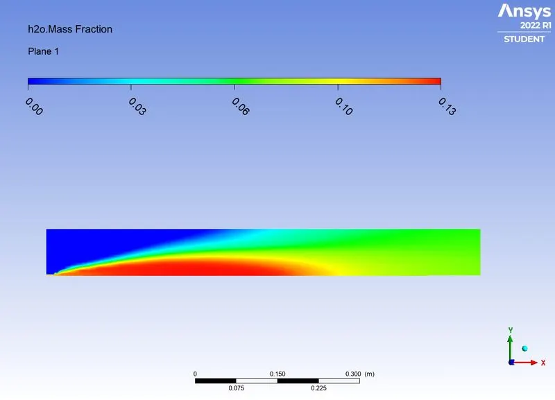
> Chart for mass fraction of H2O.
> Contour for mass fraction of CO2.
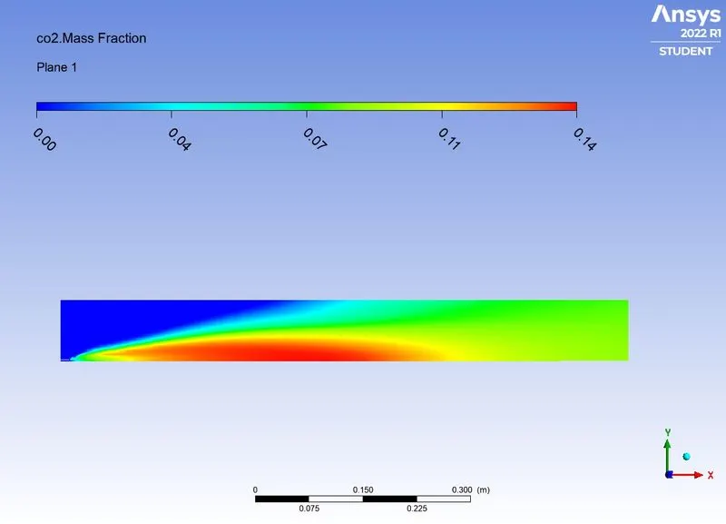
> Chart for mass fraction of CO2.
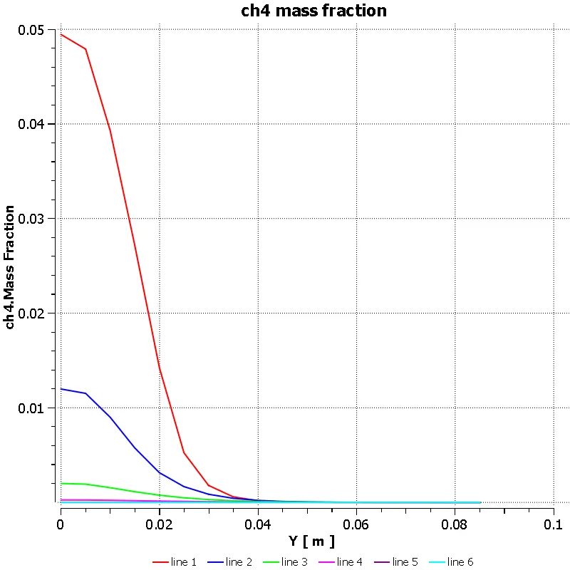
CASE 3: MASS FRACTION OF CH4 AS 0.8 AND WATER AS 0.2.
RESULTS:
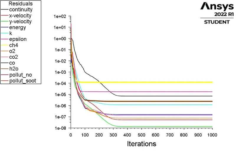
> Scaled residuals:
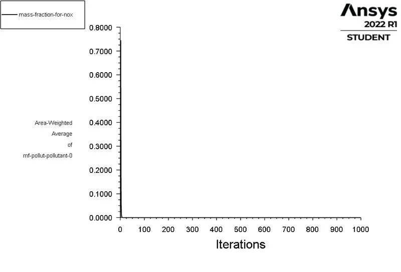
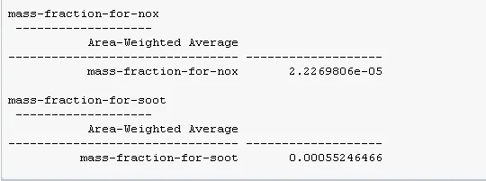
> Mass fraction of NOx report.
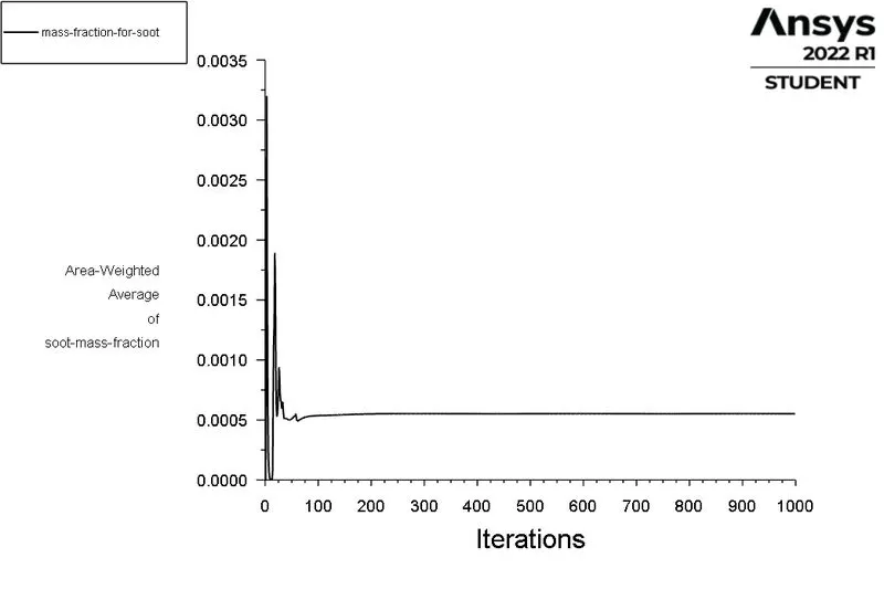
> Mass Fraction Of soot report:
POST PROCESSING:
> TEmperature contour.
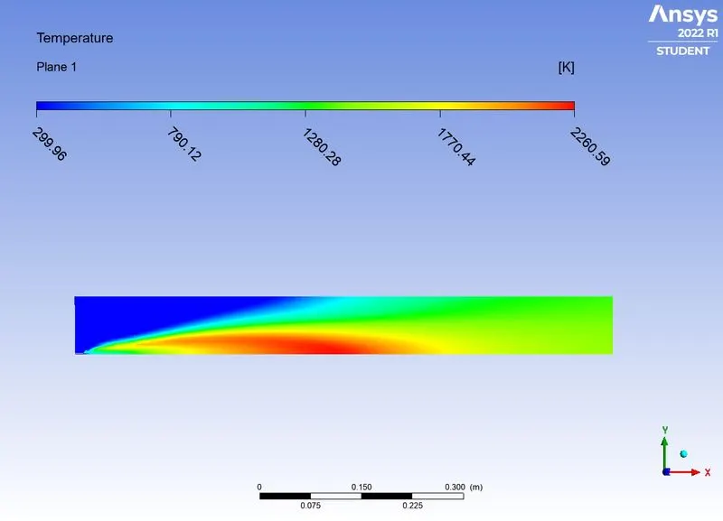
> contour for Mass fraction of NOx.
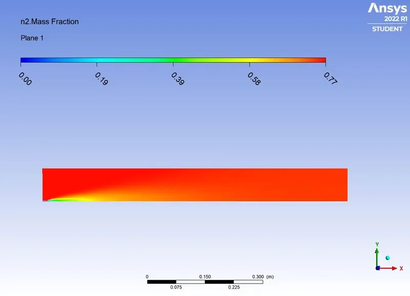
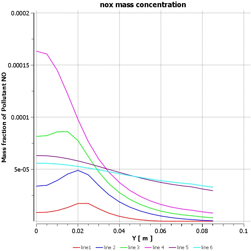
> Chart for mass fraction of NOx.
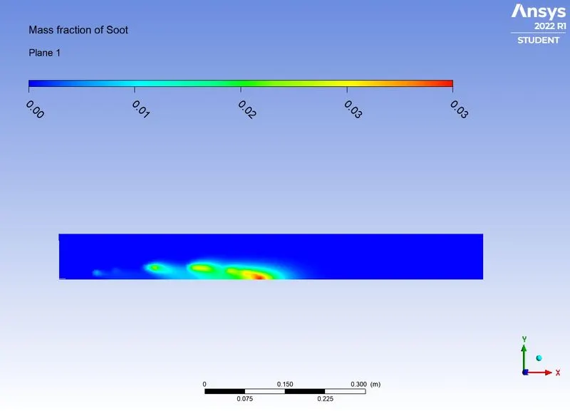
> Contour for mass fraction of soot.
> chart for mass fraction of soot.

> contour for mass fraction of ch4.
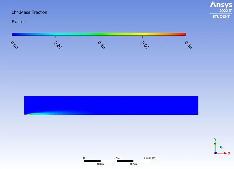
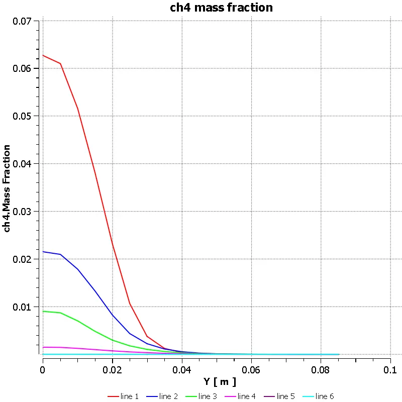
> chart for mass fraction of Ch4
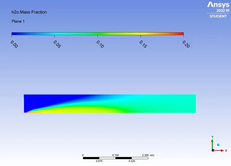
> contour for mass fraction of H2O.
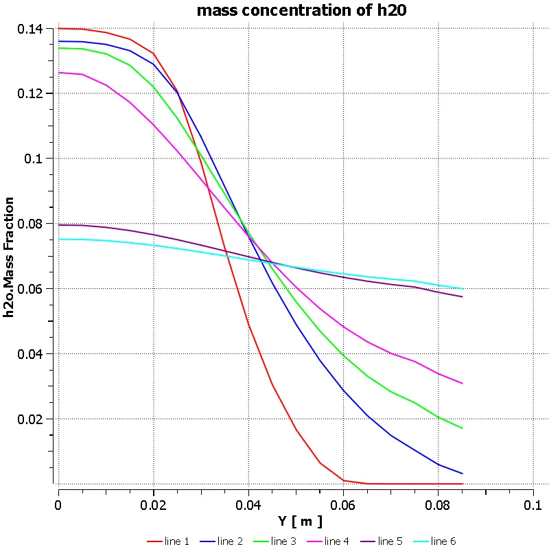
> Chart for mass fraction of H2O.
> Contour for mass fraction of CO2.
> Chart for mass fraction of CO2.
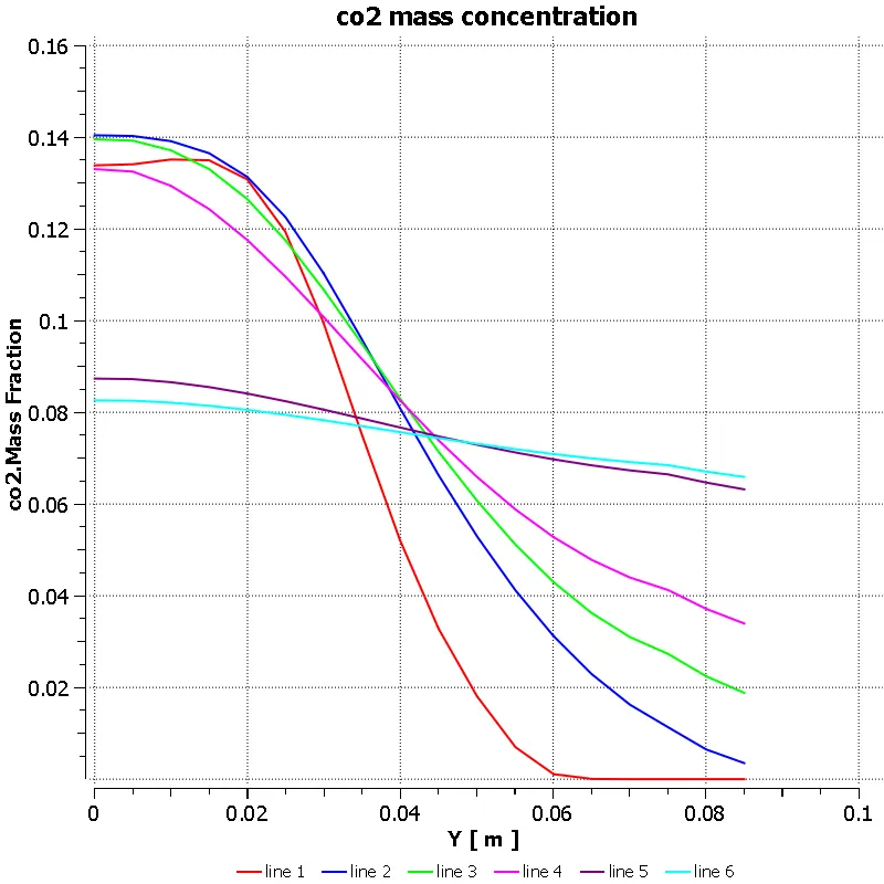
CASE 4: MASS FRACTION OF CH4 AS 0.7 AND WATER AS 0.3.
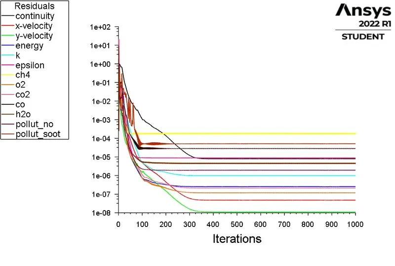
RESULTS:
> Scaled residuals:
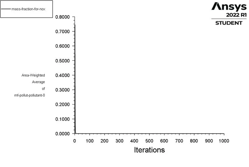
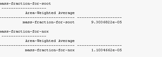
> Mass fraction of NOx report.
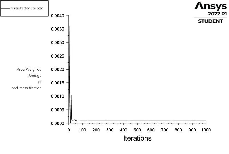
> Mass Fraction Of soot report:
POST PROCESSING:
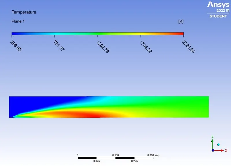
> TEmperature contour.
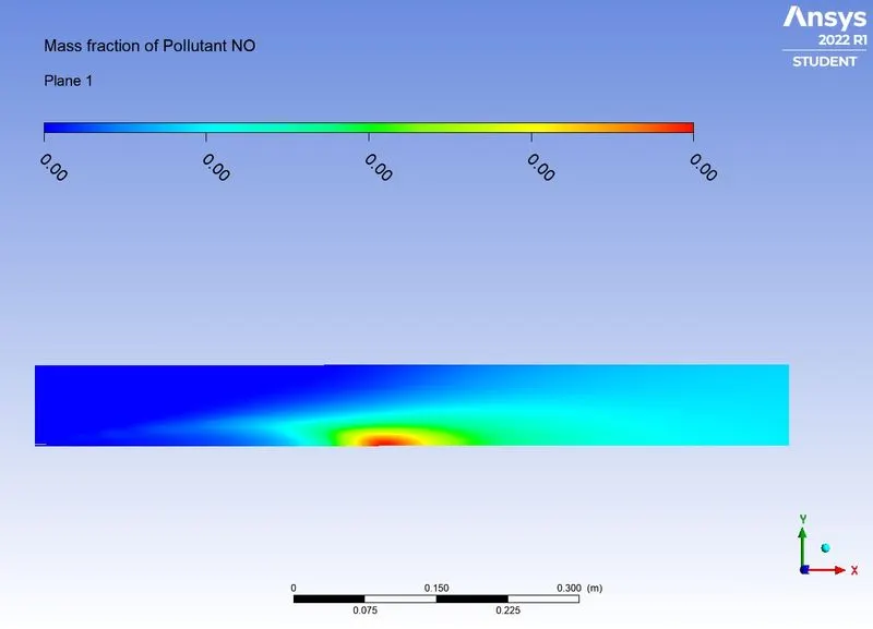
> contour for Mass fraction of NOx.
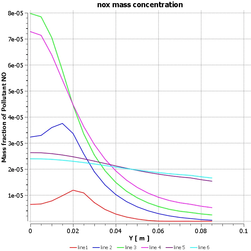
> Chart for mass fraction of NOx.
> Contour for mass fraction of soot.
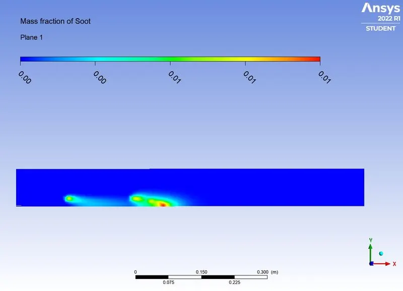
> chart for mass fraction of soot.
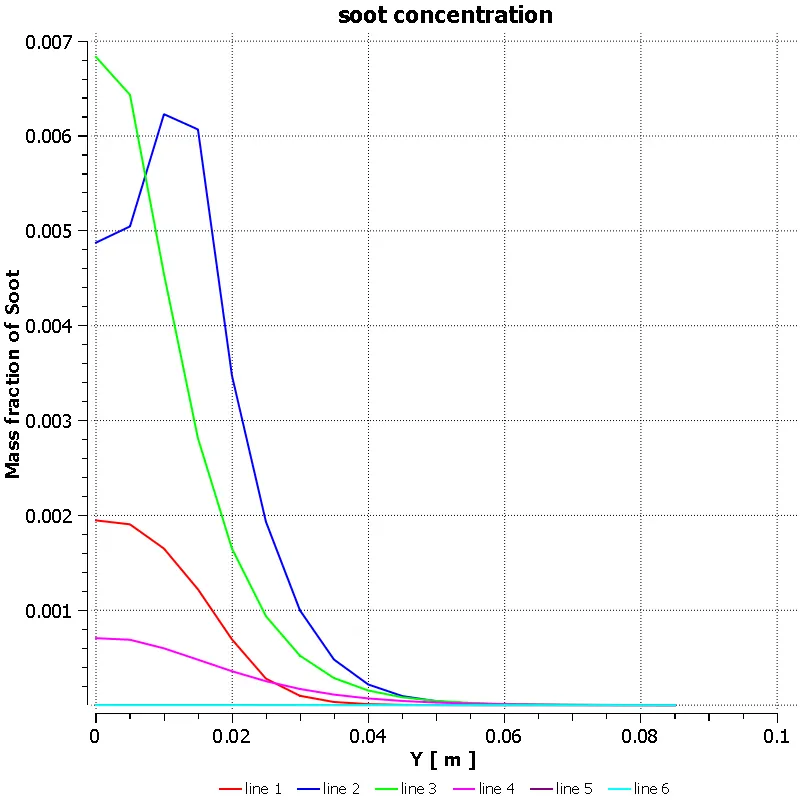
> contour for mass fraction of ch4.
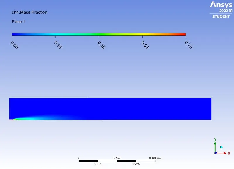
> chart for mass fraction of Ch4.
> contour for mass fraction of H2O.
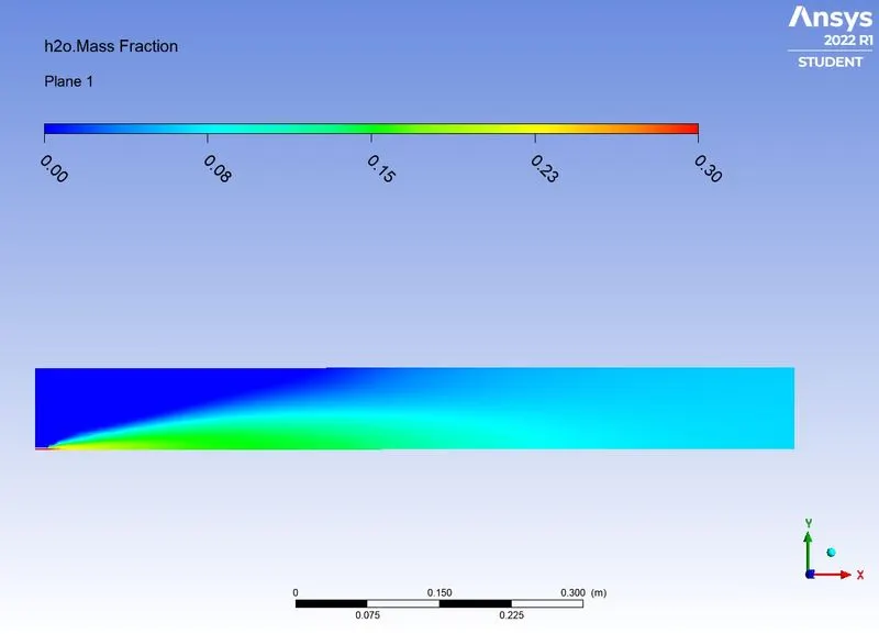
> Chart for mass fraction of H2O.
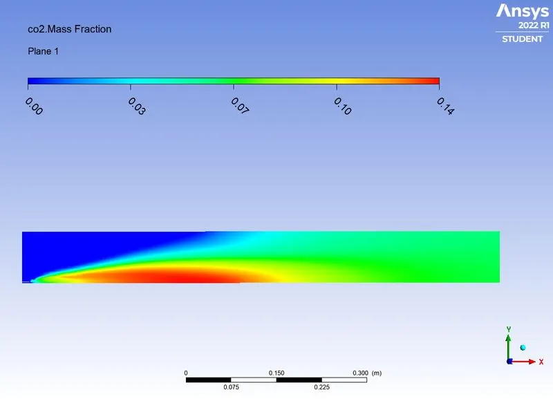
> Contour for mass fraction of CO2.
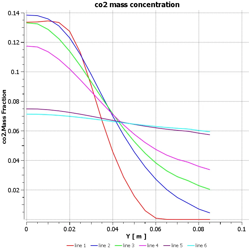
> Chart for mass fraction of CO2.
CONCLUSION:
| CASES | MASS FRACTION OF NOX | MASS FRACTION OF SOOT |
| CH4:H20::1:0 | 0.00006339872 | 0.0017521614 |
| CH4:H20::0.9:0.1 | 0.000038982 | 0.00036750296 |
| CH4:H20::0.8:0.2 | 0.00002226980 | 0.00055246466 |
| CH4:H20::0.7:0.3 |
1.1034662e-05 |
9.3036822e-05 |
> Due to increase in the water concentration the mass fraction of nox will decreases.
> As the water concentration increases the value of soot will increases.
> But the efficiency of combustion reduces as there is reduction incomplete combustion
> Decrease in flame temperature below values of 1600 K. Hence, very-low combustion temperatures will reduce soot